
In my years of experience as a foundry engineer, I have consistently observed that the control and prevention of casting defects are paramount to achieving high-quality cast components. These casting defects not only lead to significant financial losses but also compromise the structural integrity and performance of the final product. The journey toward defect-free casting involves a deep understanding of metallurgy, solidification dynamics, and process optimization. In this detailed account, I will share insights gleaned from practical applications, focusing on the intricate balance required in alloying and process design to suppress various casting defects.
The fundamental challenge in iron casting, particularly with gray and ductile irons, lies in managing the microstructure during solidification. Uncontrolled formation of graphite, cementite, or undesirable phases directly leads to casting defects such as shrinkage porosity, chilling (white iron formation), and distortion. The core principle I adhere to is that every element added and every process parameter adjusted must be evaluated for its potential to introduce or exacerbate these casting defects.
One of the most critical areas is the low-alloying of gray iron. While micro-alloying is a powerful tool for achieving high-grade specifications, it is a double-edged sword. Elements added to enhance strength or refine microstructure can simultaneously promote chilling tendencies, leading to hard spots and machining difficulties—a classic set of casting defects. For instance, elements like chromium (Cr) and molybdenum (Mo) are excellent for promoting pearlite and increasing strength. However, their excessive use strongly suppresses graphitization. The risk of forming carbides at the eutectic cell boundaries increases, which are severe casting defects that induce brittleness. Therefore, the addition must be meticulously controlled. The relationship can be conceptually summarized by a graphitization factor. Let us consider a simplified stability parameter $S$ for gray iron:
$$ S = CE – k_1 \cdot [Cr] – k_2 \cdot [Mo] + k_3 \cdot [Si] $$
Where $CE$ is the carbon equivalent, $[X]$ denotes the concentration of an element, and $k$ are empirical coefficients. A lower $S$ value indicates a higher risk of chilling casting defects.
The interaction of various elements on the propensity for casting defects like shrinkage and chilling is complex. The following table summarizes the primary effects of common alloying elements, based on my observations and standard foundry knowledge.
| Alloying Element | Primary Effect on Microstructure | Associated Risk of Casting Defects | Recommended Control Range (wt.%) |
|---|---|---|---|
| Chromium (Cr) | Promotes pearlite, refines graphite, increases hardness. | High chilling tendency, promotes carbide formation (shrinkage, hard spots). | 0.1 – 0.3 |
| Molybdenum (Mo) | Strong pearlite promoter, improves strength at elevated temperatures. | Can cause partial chilling, especially in thin sections. | 0.2 – 0.5 |
| Copper (Cu) | Promotes pearlite without strong chilling effect. | Minimal direct defect risk; can help offset other elements’ chilling. | 0.5 – 1.5 |
| Tin (Sn) | Very effective pearlite promoter. | Brittleness if excessive; can lead to intergranular embrittlement. | 0.05 – 0.1 |
| Vanadium (V) | Refines pearlite and graphite. | Powerful carbide stabilizer; high risk of chilling defects. | < 0.1 |
| Phosphorus (P) | Improves fluidity. | Forms hard, brittle phosphide eutectic (steadite) at levels >0.1%, a significant casting defect. | < 0.06 for alloyed iron |
A pivotal strategy in my practice is to minimize alloy addition while meeting specifications. The first step is always to optimize the base composition. After deciding on the carbon equivalent (CE), I aim to lower the silicon (Si) content as much as possible to increase the potential for undercooling, which is then controlled through inoculation. The sequence for alloy addition to prevent casting defects related to soft spots (free ferrite) and to ensure strength is as follows:
- Add elements that delay the formation of free ferrite (e.g., small amounts of Sn or Cu).
- To ensure a fully pearlitic matrix, add elements that refine pearlite and have a quenching effect (e.g., controlled amounts of Cr, Mo).
- Leverage synergistic effects using composite additions. For example, a combination of Cu + Sn + Cr can reduce the individual chilling effect of Cr while still achieving pearlite refinement. This complementary action is crucial for complex castings with varying section thicknesses.
Inoculation is not merely a step but a vital countermeasure against casting defects induced by alloying. A well-executed inoculation process neutralizes chilling tendencies, promotes uniform graphite formation, and reduces shrinkage sensitivity. The effectiveness of inoculation in reducing casting defects can be modeled by its impact on the number of graphite nuclei. The number of graphite nodules $N$ in ductile iron, for instance, relates to inoculation potency and fading time $t$:
$$ N = N_0 \cdot e^{-\lambda t} $$
where $N_0$ is the initial nodule count post-inoculation and $\lambda$ is the fading constant. A higher $N$ generally correlates with fewer shrinkage-related casting defects.
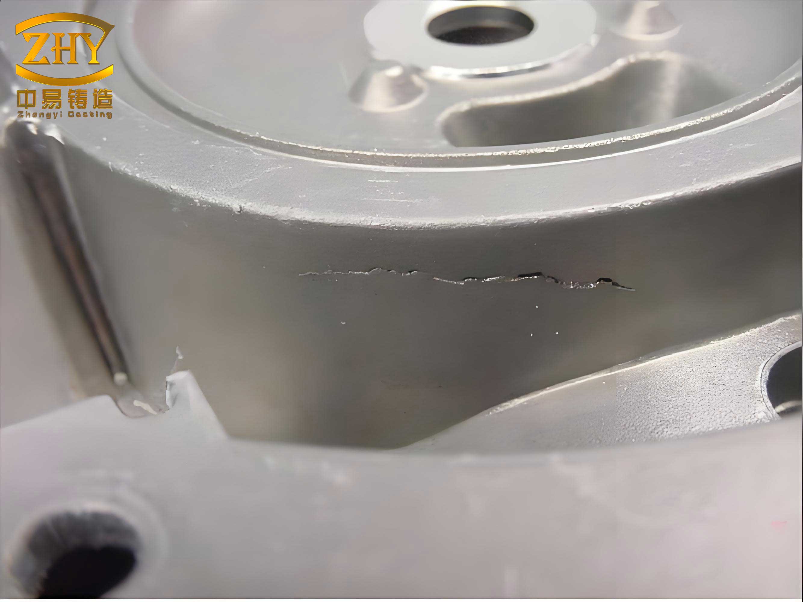
Visualizing common casting defects, as shown, reinforces the need for meticulous process control. Moving from theory to practice, I recall a specific challenge with a thin-walled hub liner casting, similar to the described case. The casting was small, with a weight of approximately 0.15 kg and critical sections as thin as 4 mm. The primary casting defect was severe shrinkage porosity in the inner diameter after machining, leading to a scrap rate of 30-40%. The root cause was identified as inadequate feeding at several thermal hotspots. Without the possibility of using conventional risers due to the geometry, the solution required a multi-pronged approach. First, I tightened the chemical composition: Carbon Equivalent (CE) between 4.3-4.5, silicon between 1.8-2.2%, and manganese below 0.6%. Secondly, and most ingeniously, the product design was slightly modified by adding small recesses (0.5 mm) at the thermal junction points. This simple change effectively made the wall thickness more uniform, eliminating the isolated hotspots that were the origin of the shrinkage casting defects. The pouring temperature was maintained above 1380°C to ensure fluidity. This combination of compositional control and subtle design alteration completely eradicated the shrinkage porosity defect.
Another pervasive category of casting defects involves distortion and internal stresses, particularly in large, thin-walled plates. A case in point is a large end cover plate with dimensions around 1800 x 800 mm and a primary wall thickness of only 8 mm. The initial process resulted in significant warping, with the center bowing upwards by 5-10 mm—a classic distortion casting defect. The corrective strategy focused on balancing thermal gradients and stresses during pouring and solidification. The gating system was radically redesigned. I implemented a unidirectional, open gating system placed along the thinner edge of the casting. The area ratios were set as $A_{\text{choke}} : A_{\text{runner}} : A_{\text{ingates}} = 1 : 1.5 : 2.0$. Crucially, the mold was tilted at an angle of 15-20 degrees during pouring, with the gating system at the higher end. This tilt, combined with an increased pouring temperature (1360-1380°C) and faster pouring time (15-20 seconds), ensured more uniform heat distribution. The thermal stress $\sigma_{th}$ induced during cooling can be approximated by:
$$ \sigma_{th} \approx E \cdot \alpha \cdot \Delta T_{gradient} $$
where $E$ is Young’s modulus, $\alpha$ is the thermal expansion coefficient, and $\Delta T_{gradient}$ is the temperature difference across the casting. By minimizing $\Delta T_{gradient}$ through tilted pouring and controlled gating, we minimized $\sigma_{th}$ and thus the distortion casting defects. Additional auxiliary measures included coating the mold with graphite powder, ensuring uniform mold hardness (75-85), and securely bolting the mold flasks together.
The interplay between section size (modulus), alloy content, and the resulting microstructure is critical for predicting casting defects. For production consistency, I developed internal guidelines correlating the casting modulus $M$ (Volume/Surface Area) with the required alloy addition to achieve a target pearlite percentage. This relationship is often non-linear. For a family of cylinder liner castings, the data can be summarized as follows:
| Casting Modulus, M (cm) | Required Total Pearlite Promoter (e.g., Cr+Cu+Sn) (wt.%) for >95% Pearlite | Typical Result if Under-Alloyed (Casting Defect) | Typical Result if Over-Alloyed (Casting Defect) |
|---|---|---|---|
| 0.3 – 0.5 | 0.4 – 0.7 | Free ferrite at core, reduced hardness | Chilled edges, carbides, shrinkage |
| 0.5 – 1.0 | 0.3 – 0.6 | Free ferrite bands, inconsistent properties | Intergranular carbides, brittleness |
| > 1.0 | 0.2 – 0.4 | Substantial ferrite, low strength | Massive carbides in heavy sections |
This empirical table is instrumental in preempting microstructure-related casting defects. It is clear that a one-size-fits-all approach to alloying invariably invites defects. The goal is always to add the minimum necessary amount. A useful metric I employ is the “Defect Risk Index” $DRI$ for a given iron melt, which attempts to quantify the overall tendency towards common casting defects:
$$ DRI = \frac{[Cr] + 0.7[Mo] + 2[V]}{CE} + 10 \cdot ([P] – 0.05) $$
For general gray and ductile irons, I strive to maintain a $DRI < 0.5$ for castings with moderate section sensitivity. A higher $DRI$ mandates more aggressive inoculation or process adjustments.
Furthermore, the handling of phosphorus (P) in alloyed irons deserves special emphasis. While P improves fluidity, in alloyed irons it readily forms hard phosphides, especially when elements like chromium are present. These phosphides, concentrated at grain boundaries, are severe casting defects that drastically reduce toughness. My rule is to keep phosphorus below 0.06% in alloyed irons intended for demanding applications. The susceptibility to phosphide formation $P_{sus}$ can be expressed as:
$$ P_{sus} = [P] \cdot (1 + 5[Cr] + 3[V]) $$
Keeping $P_{sus}$ below a threshold of 0.1 is a good practice to avoid this specific embrittlement casting defect.
Finally, the human and procedural factors cannot be overlooked in the battle against casting defects. Standardized procedures for mold preparation, pouring, and cooling are as important as the chemistry. Regular training of foundry personnel to recognize the early signs of process drift that lead to casting defects is an investment that pays continuous dividends. In conclusion, the mitigation of casting defects is a holistic discipline. It requires a synergistic application of metallurgical science, practical ingenuity in gating and feeding design, rigorous process control, and a culture of continuous improvement. Every casting defect is a lesson; analyzing its root cause systematically provides the knowledge to not only fix that specific issue but to strengthen the entire production process against future failures. The journey is ongoing, but with a methodical approach focused on controlling solidification and microstructure, the goal of consistent, high-integrity castings with minimal casting defects is entirely achievable.