
In the contemporary landscape of manufacturing, particularly within the automotive and prototyping sectors, the demand for rapid production of complex, high-integrity metal components has never been greater. Traditional development cycles are often bottlenecked by the time and cost associated with tooling and iterative physical trials. Herein lies the significant value of integrating advanced numerical simulation techniques with innovative sand casting processes. This article, from my perspective as an engineer immersed in this field, delves into a comprehensive exploration of how simulation drives the optimization of a rapid sand casting process for a critical component: the engine cylinder head. The fusion of computational analysis with rapid prototyping principles enables a paradigm shift from experience-based guesswork to a predictive, science-driven manufacturing approach.
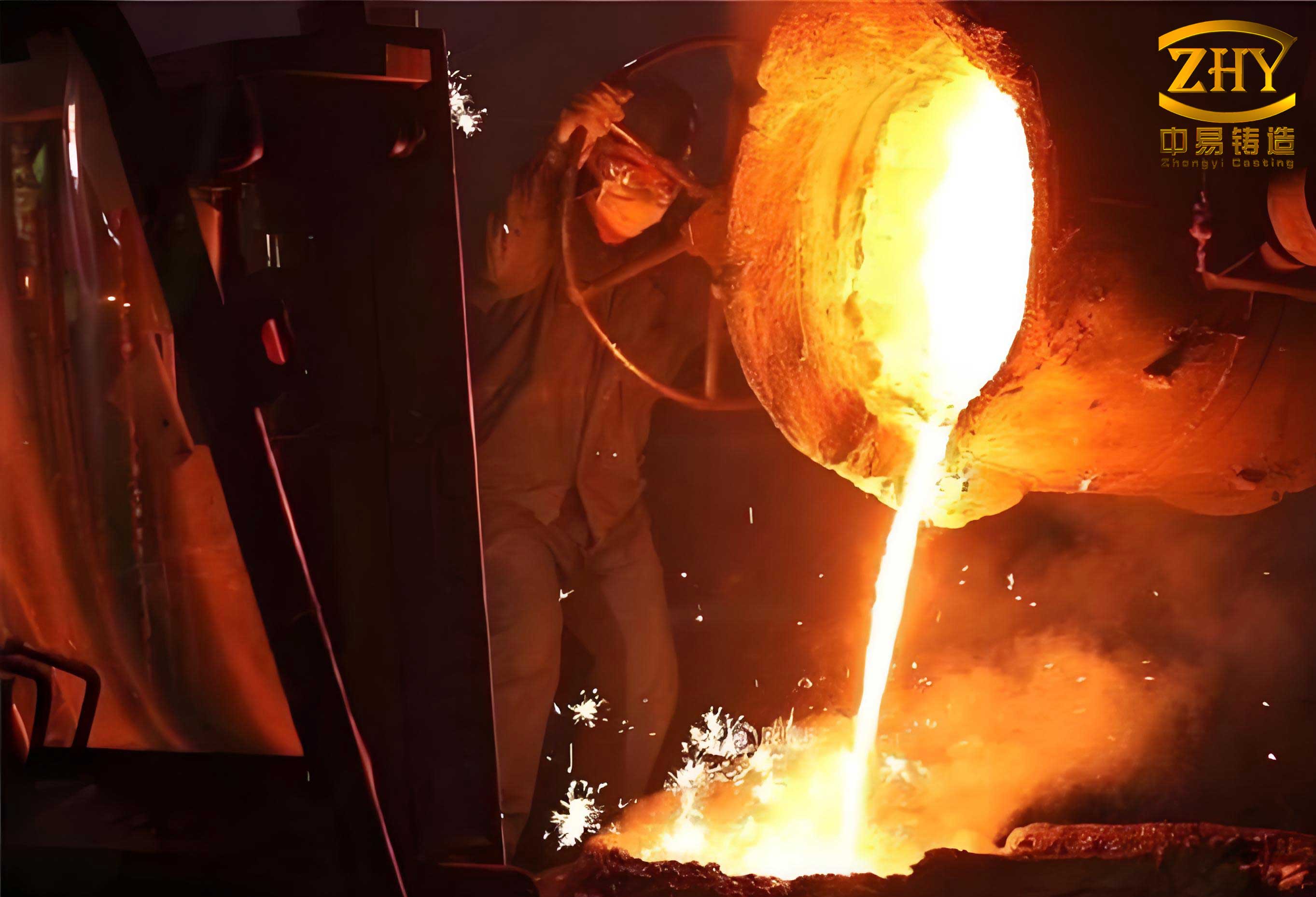
The foundational process under consideration is rapid sand casting, which synergizes traditional foundry methods with modern additive manufacturing. The core idea is to use Stereolithography (SLA) or similar 3D printing technologies to fabricate the sand molds and cores directly from a digital model, bypassing the need for hard tooling. This is particularly powerful for low-volume production, prototype development, and complex geometries that are challenging for conventional pattern making. The fundamental steps of a traditional sand casting process are visually summarized below, which forms the baseline for the rapid variant.
My focus is on the virtual prototyping phase that precedes any physical pour. By employing finite element method (FEM) based simulation software, we can virtually replicate the entire casting process. This allows for the analysis of mold filling, solidification, thermal gradients, and the prediction of defects such as shrinkage porosity, cold shuts, and trapped air. The financial and temporal savings are substantial, as potential issues are identified and rectified in the digital domain.
Theoretical Underpinnings of Casting Simulation
The numerical simulation of sand casting is governed by the fundamental laws of physics: conservation of mass, momentum, and energy. Solving these coupled equations for a transient, multiphase (liquid-solid-air) system within a complex geometry is the task of the simulation engine.
The fluid flow during mold filling is typically modeled as an incompressible, turbulent flow. The governing equations are the Navier-Stokes equations, often simplified using algorithms like Volume of Fluid (VOF) to track the advancing metal front. The general momentum conservation equation can be expressed as:
$$
\rho \left( \frac{\partial \mathbf{v}}{\partial t} + \mathbf{v} \cdot \nabla \mathbf{v} \right) = -\nabla p + \mu \nabla^2 \mathbf{v} + \rho \mathbf{g} + \mathbf{S}
$$
where $\rho$ is the density, $\mathbf{v}$ is the velocity vector, $t$ is time, $p$ is pressure, $\mu$ is the dynamic viscosity, $\mathbf{g}$ is gravity, and $\mathbf{S}$ represents source terms (e.g., Darcy term for flow in mushy zones).
The energy equation, crucial for solidification analysis, is given by:
$$
\rho c_p \frac{\partial T}{\partial t} + \rho c_p \mathbf{v} \cdot \nabla T = \nabla \cdot (k \nabla T) + \dot{Q}_{latent}
$$
Here, $c_p$ is the specific heat, $T$ is temperature, $k$ is the thermal conductivity, and $\dot{Q}_{latent}$ is the latent heat source term released during the phase change from liquid to solid. For a binary alloy, the fraction of solid ($f_s$) is often calculated using a simplified Scheil or lever rule model under non-equilibrium conditions:
$$
f_s = 1 – \left( \frac{T_m – T}{T_m – T_{liquidus}} \right)^{\frac{1}{1-k_0}}
$$
where $T_m$ is the melting point of the pure solvent, $T_{liquidus}$ is the liquidus temperature of the alloy, and $k_0$ is the equilibrium partition coefficient.
The interaction between the molten metal and the sand mold is defined by a critical boundary condition: the interfacial heat transfer coefficient (IHTC). This coefficient is not a constant but a complex function of interface pressure, air gap formation, and surface roughness. It is often approximated with a temperature-dependent function derived from inverse modeling:
$$
h_{interface}(T) = a + b \cdot \exp(c \cdot T)
$$
where $a$, $b$, and $c$ are empirical constants determined for specific metal-mold systems.
Process Design and Pre-Simulation CAD Modeling
Before a simulation can be run, a robust digital model of the entire casting system must be created. For an engine cylinder head, this involves several critical decisions made in a CAD environment:
- Parting Line Selection: The plane that separates the cope (top) and drag (bottom) molds. It must allow for proper core placement and easy mold stripping.
- Core Design: The internal passages for coolant and oil are formed by sand cores. These must be designed for strength, proper venting, and ease of assembly within the mold.
- Gating System Design: This is the channel system that guides molten metal into the mold cavity. For the cylinder head, a bottom-gating system is often preferred to promote tranquil filling and reduce turbulence and oxide formation.
- Feeding System (Risers): Risers are reservoirs of molten metal that feed the casting as it solidifies and shrinks, preventing shrinkage porosity. Their size and location are paramount, often calculated using Chvorinov’s Rule for modulus:
$$
t_{solidification} \propto \left( \frac{V}{A} \right)^n = M^n
$$
where $t_{solidification}$ is the local solidification time, $V$ is volume, $A$ is cooling surface area, $M$ is the geometric modulus, and $n$ is an exponent (typically ~2). A riser must have a larger modulus than the region it feeds and be placed to ensure directional solidification toward it.
Modern CAD systems for sand casting can automate much of this design work, generating gating and risering geometries based on part geometry and material properties. The output is a complete 3D assembly of the casting, cores, gating, and risering system, ready for meshing. For our ZL105 aluminum alloy cylinder head, the key material properties used in design and simulation are summarized below:
| Property Category | Parameter | Value / Range | Remarks |
|---|---|---|---|
| Chemical Composition (wt.%) | Si | 4.5 – 5.5 | Primary alloying elements for strength and castability. |
| Cu | 1.0 – 1.5 | ||
| Mg | 0.4 – 0.6 | ||
| Al | Balance | ||
| Thermal Properties | Liquidus Temperature, $T_L$ | ~622 °C | Onset of solidification. |
| Solidus Temperature, $T_S$ | ~536 °C | Completion of solidification. | |
| Latent Heat of Fusion, $L_f$ | ~389 kJ/kg | Critical for solidification modeling. | |
| Process Parameters | Pouring Temperature | 690 – 720 °C | Superheat above $T_L$ is typically 50-100°C. |
Simulation Workflow: From Mesh to Results
The journey from a CAD model to actionable insights involves a structured simulation workflow, which I will outline in detail.
Step 1: Geometry Import and Meshing. The assembled CAD model is imported into the pre-processor of simulation software (e.g., ProCAST, MAGMASOFT). The geometry is then discretized into a finite element mesh, typically tetrahedral elements for complex shapes. Mesh density is critical: too coarse, and accuracy suffers; too fine, and computation time becomes prohibitive. A common rule is to have at least 3-4 elements across the thinnest section wall. For a cylinder head, this can result in several million elements. The mesh must be checked for quality (aspect ratio, skewness) to ensure numerical stability.
Step 2: Assignment of Materials and Boundary Conditions. Each component in the model is assigned its material properties from a database:
- Casting: ZL105 aluminum alloy, with temperature-dependent properties for density, viscosity, specific heat, and thermal conductivity.
- Mold & Cores: Silica sand mixed with phenolic urethane resin binder. Its key property is its low thermal conductivity, which governs the cooling rate.
- Chills (if used): Materials with high thermal conductivity (e.g., copper, iron) to locally accelerate solidification.
The initial conditions are then defined: pouring temperature for the metal, ambient temperature for the mold. Boundary conditions include the interfacial heat transfer coefficient (IHTC) between metal and sand, and heat loss from the outer mold surfaces to the environment via radiation and convection.
Step 3: Solver Execution. The core numerical solver iteratively solves the coupled fluid flow and heat transfer equations over discrete time steps. The filling phase simulation tracks the advancement of the liquid metal front, calculating velocities, pressures, and potential areas of turbulence or air entrapment. Once filling is complete, the solidification phase simulation begins, tracking the evolution of temperature fields, solid fraction, and feeding flow in the mushy zones. This is the most computationally intensive part of the process.
Step 4: Post-Processing and Analysis. The raw data from the solver is visualized and interpreted. Key results for a sand casting analysis include:
- Filling Sequence Animations: To visualize flow patterns and identify potential cold shuts or mistruns.
- Solid Fraction Plots over Time: To assess the directionality of solidification and identify isolated liquid pools (“hot spots”) that may lead to shrinkage defects.
- Temperature Gradient Maps: To understand cooling rates, which influence microstructure and mechanical properties.
- Shrinkage Porosity Prediction: Using criteria functions (e.g., Niyama criterion for aluminum alloys) that combine local thermal parameters like temperature gradient $G$ and cooling rate $\dot{T}$ to predict the likelihood of microporosity formation:
$$
Niyama = \frac{G}{\sqrt{\dot{T}}}
$$
Areas with a Niyama value below a critical threshold (e.g., ~1 °C0.5·min0.5/mm for Al alloys) are flagged as high-risk for shrinkage porosity.
Case Study: Engine Cylinder Head in Rapid Sand Casting
Applying this workflow to the specific case of an aluminum cylinder head manufactured via rapid sand casting yields profound insights. The initial CAD design featured a one-sided bottom gating system and strategically placed top risers.
The filling simulation confirmed the efficacy of the bottom-gating design. The metal entered the mold cavity calmly from the base, with the liquid front rising steadily and uniformly. This minimizes turbulence, oxidation, and sand erosion—common concerns in sand casting. The total fill time was predicted to be approximately 16 seconds, with the final regions to fill being the uppermost sections of the risers, confirming adequate metallostatic pressure.
The solidification analysis, however, is where the true predictive power shines. The simulation clearly showed a progressive solidification sequence: the thin outer walls of the cylinder head solidified first, followed by the thicker internal sections like valve guides and combustion chambers. The thermal analysis can be quantified by examining the cooling rates in different sections. For example, the solidification time $t_{sol}$ for a thin wall versus a thick boss can differ by an order of magnitude, which is predicted accurately by the simulation and follows Chvorinov’s rule.
The most critical output was the prediction of shrinkage defects. The software’s porosity module, applying a Niyama-like criterion, highlighted areas at risk. The initial design showed a few potential hot spots in thick junction areas that were not directly fed by a riser. The predicted porosity percentage $P$ in these localized zones was estimated by the software’s internal models, which often relate to the fraction of isolated liquid at the end of feeding:
$$
P \propto \beta \cdot (1 – f_s)_{final}
$$
where $\beta$ is the volumetric shrinkage coefficient of the alloy (approx. 0.04-0.06 for Al-Si alloys).
Design Optimization Based on Simulation: The simulation is not merely a passive analysis tool but an active design optimizer. Based on the initial results:
- The size and neck connection of one riser was modified to improve its feeding efficiency.
- A small chill was virtually added to a thick section to locally increase the cooling rate and promote directional solidification toward a riser.
- The pouring temperature was fine-tuned within the 690-720°C window to balance fluidity and total solidification shrinkage.
A subsequent simulation run of the modified design showed a significant reduction in the predicted size and number of shrinkage porosity regions. The final predicted porosity distribution was largely uniform and dispersed, with the maximum local porosity fraction in any critical load-bearing area falling below the acceptable threshold of 10%. The final, optimized process parameters for this rapid sand casting application can be summarized as follows:
| Process Stage | Parameter | Optimized Value / Setting |
|---|---|---|
| Gating & Pouring | Gating Type | Single-Side Bottom Gating |
| Pouring Temperature | 700 °C | |
| Pouring Rate / Time | ~1.2 kg/s (Total fill time: 16 s) | |
| Feeding System | Riser Type & Number | 2 Top Riser (Modified Geometry) |
| Chill Application | 1 Local Chill in Critical Junction | |
| Material & Mold | Alloy | ZL105 (Al-Si-Cu-Mg) |
| Mold Material | Phenolic Urethane-Bonded Silica Sand | |
| Key Simulation Metric | Max Local Porosity (Predicted) | < 10% (dispersed) |
Validation and Broader Implications
The ultimate test of any simulation is physical validation. The optimized design, with gating and risering derived from the simulation, was used to create SLA-printed patterns and core boxes for the rapid sand casting process. The actual casting was poured, and the resulting cylinder head was subjected to non-destructive testing (NDT) like X-ray radiography and sectioning for macro-examination. The findings correlated strongly with the simulation predictions: no major shrinkage cavities were present, and any micro-porosity was finely dispersed in non-critical areas, confirming the part’s structural integrity.
The implications of this successful integration are vast. For rapid sand casting, numerical simulation acts as a powerful accelerator and quality assurance tool. It drastically reduces the number of physical “try-out” casts needed, saving significant material, energy, and time. It enables the production of “right-first-time” prototypes and low-volume parts, which is invaluable for industries like automotive, aerospace, and heavy machinery where development cycles are critical. Furthermore, it empowers foundries to tackle increasingly complex geometries with confidence, knowing that potential defects can be identified and mitigated digitally before a single grain of sand is bonded.
Future Perspectives and Conclusion
The frontier of sand casting simulation continues to advance. Key areas of development include:
- Microstructure and Mechanical Property Prediction: Coupling thermal history from casting simulation with models for grain size, secondary dendrite arm spacing (SDAS), and phase formation to predict final mechanical properties like yield strength and fatigue life.
- Stress and Distortion Analysis: Simulating the development of residual stresses and warpage during and after solidification, which is crucial for dimensional accuracy and post-casting machining.
- Integration with Additive Manufacturing of Molds: As binder jetting of sand becomes more prevalent, simulation will need to account for the anisotropic properties of 3D-printed sand molds, which may have different permeability and thermal characteristics compared to traditionally compacted sand.
- AI-Driven Optimization: Using machine learning algorithms to automatically explore vast design spaces (e.g., riser locations, gating designs) and propose optimal configurations based on simulation results, moving from simulation-assisted to simulation-optimized design.
In conclusion, the numerical simulation of filling and solidification is no longer a luxury but a fundamental pillar of modern, efficient, and high-quality sand casting operations, especially in the context of rapid prototyping and manufacturing. It transforms the art of foundry into a quantifiable engineering discipline. By providing a virtual window into the complex physical phenomena occurring during casting, it enables unprecedented levels of control, optimization, and predictability. For components as demanding as an engine cylinder head, this technology is indispensable for achieving the required quality, performance, and speed to market. The continued evolution of simulation capabilities promises to further solidify its role as the cornerstone of intelligent casting production.