
The efficient and cost-effective production of molds, particularly for sand casting, remains a critical challenge in modern manufacturing. The core of this challenge lies not only in the machining of complex geometries but also in the intelligent planning of toolpaths to minimize tool wear, prevent catastrophic tool failure, and reduce overall cycle time. Based on extensive practical experience, this article delves into a comprehensive methodology for optimizing Computer-Aided Manufacturing (CAM) programming for intricate sand casting molds. The focus is on a systematic approach that prioritizes process stability and economic efficiency, using the detailed programming and machining of a complex sand casting mold as a foundational case study.
Compared to injection molds, the design of a mold for sand casting involves distinct considerations. An injection mold is engineered for high precision and mass production, aiming to form a final product in a single cycle. In contrast, a sand casting mold produces a rough casting—a near-net-shape blank that must undergo subsequent machining to achieve final dimensional accuracy and surface finish. Therefore, the design of a sand casting mold must account for several foundry-specific factors beyond basic shrinkage, including machining allowances for different surfaces, draft angles for pattern removal, and fillet radii to aid metal flow and reduce stress concentrations. Some intricate features may even be solidified in the mold and later machined in the casting. This fundamental difference dictates a unique approach to machining the mold cavity and core themselves.
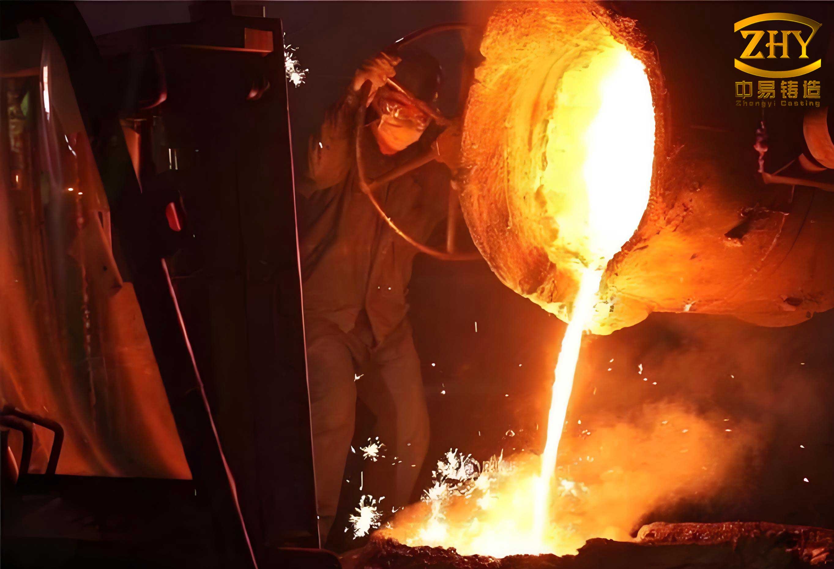
The structural characteristics of a typical sand casting mold present specific machining challenges. The core (or drag) mold often features a complex cavity with deep pockets, thin ribs, and sharp internal corners. Conversely, the cope mold features high, slender projections that correspond to these cavities. The primary difficulty arises during roughing and finishing of these deep, narrow areas. Using a small-diameter tool is necessary to access tight spaces and perform corner cleaning, but the required depth of cut can lead to a high length-to-diameter ratio for the tool. This excessive overhang drastically reduces tool rigidity, leading to deflection, poor surface finish, chatter, and a high probability of tool breakage. The economic impact of a broken tool in the middle of an unattended machining cycle is significant, involving not only tool cost but also downtime for tool change, potential workpiece damage, and rescheduling.
Therefore, a core objective in optimizing the CNC program for a sand casting mold is to strategically manage these risky operations. This involves a holistic strategy encompassing pre-machining preparation, intelligent toolpath planning, and meticulous parameter selection. The following sections detail this optimization framework.
1. Pre-Machining and Workpiece Setup
Before any CNC machining on a multi-axis milling center, significant preparatory work should be completed on more rigid and powerful machine tools. For a mold block material like QT600 (a nodular iron), the initial steps involve:
- Primary Sawing/Casting: Obtaining a rough block slightly larger than the final mold dimensions.
- Planer or Gantry Milling: Machining the six primary faces of the block. The bottom face and the four side faces are machined to final dimensions, establishing the outer envelope. The top face (which will become the parting plane or a reference from it) is roughed, leaving a uniform stock allowance (e.g., 1-2 mm) for final finishing on the CNC machine. This step ensures a square, dimensionally accurate workpiece with clean datum surfaces.
- Establishing Physical Datums: At this stage, key datums for the CNC setup are created. Typically, two precision dowel pin holes are drilled, reamed, and tapped on the parting plane periphery. The line connecting these holes defines a primary axis (e.g., X-axis), and their midpoint can define an origin. This method provides a robust, repeatable fixturing reference far superior to edge-finding on a rough surface.
The workpiece is then transferred to the CNC machining center. It is crucial to use a vise or fixture that clamps on the pre-machined sides, avoiding any interference with the areas to be machined. The established dowel pin holes are used with pins or a fixture to accurately locate the part, minimizing setup error. The Work Coordinate System (WCS) in the CNC control is then set relative to these physical datums. For a cavity mold, Z-zero is typically set on the finished parting plane. For a core mold, Z-zero is often set at the highest point of the core projection.
2. Strategic Toolpath Planning and Optimization
The generation of efficient and safe toolpaths is the heart of the optimization process. The overarching principle is to use the largest possible tool for as much of the material removal as possible, only resorting to smaller tools for areas geometrically inaccessible to larger ones. The process follows a staged approach:
| Stage | Objective | Tool Type | CAM Operation | Key Optimization Focus |
|---|---|---|---|---|
| 1 | Finish Parting Plane | Face Mill (ø37.5 mm) | Face Milling | Sequential clamping to access entire plane; finalize Z-zero datum. |
| 2 | Bulk Roughing | Flat End Mill (ø20 mm) | Volume Clearance / Pocketing | Region partitioning to minimize air cutting; adaptive stepdown. |
| 3 | Secondary Roughing | Flat End Mill (ø8 mm, ø4 mm) | Rest Machining / Local Pocketing | Define restricted machining zones based on leftover material; helical ramping. |
| 4 | Semi-Finishing & Finishing | Ball End Mill (ø6 mm, ø4 mm) | 3D Contour / Scallop / Parallel | Stepover control; toolpath smoothing; corner slowing. |
| 5 | Feature Machining | Drills, Reamers | Drilling, Boring | Correct hole-making sequence (Drill→Core Drill→Bore/Ream). |
2.1 Bulk Roughing with Region Partitioning
Instead of generating a single toolpath for the entire cavity, the mold is intelligently segmented into distinct machining regions (e.g., main cavity, rib networks, peripheral slots). Separate pocketing operations are then applied to each region. This prevents the tool from undertaking long, rapid traversals across already machined areas, significantly reducing non-cutting time. The material removal rate for roughing can be modeled by the formula for Metal Removal Rate (MRR):
$$ MRR = a_p \times a_e \times f_z \times Z \times N $$
Where:
$a_p$ = Axial depth of cut (mm),
$a_e$ = Radial stepover (mm),
$f_z$ = Feed per tooth (mm/tooth),
$Z$ = Number of teeth on the cutter,
$N$ = Spindle speed (RPM).
For the initial ø20 mm roughing, $a_p$ can be aggressive (e.g., 1-2 mm), and $a_e$ can be 40-50% of the tool diameter. The goal is high MRR while maintaining stable cutting forces.
2.2 Secondary Roughing with Rest Material Awareness
After the large tool completes its work, significant “rest material” remains in corners, between ribs, and other confined areas. Modern CAM software’s “rest machining” function automatically calculates these areas based on the previous tool’s geometry. The critical optimization here is to define a maximum depth and a bounding zone for the smaller tool (e.g., ø8 mm). If the software is allowed to search the entire part, it will generate paths in deep areas where the small tool cannot safely reach due to leftover bulk material from the first pass. By restricting the operation to specific Z-level ranges and closed boundaries, we ensure the small tool only machines areas where the residual stock is thin and manageable. The axial depth of cut for these long, slender tools must be severely reduced. A safe rule of thumb is:
$$ a_{p,\text{small}} \leq 0.5 \times D \times \left(\frac{L}{D}\right)^{-1} $$
Where $D$ is the tool diameter and $L$ is the overhang length. For an $L/D$ ratio of 8, $a_p$ might be limited to 0.06 × D.
2.3 Optimized Finishing Parameters
Finishing a sand casting mold requires a balance between surface quality and tool life. The key parameter is the maximum stepover ($a_e$), which directly controls the cusp height ($h$). For a ball-end mill, the relationship is:
$$ h = R – \sqrt{R^2 – \left(\frac{a_e}{2}\right)^2} $$
Where $R$ is the ball radius. To achieve a required cusp height, the necessary stepover can be derived. Furthermore, for the fragile ø4 mm ball-end mill, the federate ($F$) must be reduced. A modified federate calculation considering tool strength is:
$$ F_{\text{small}} = f_{z,\text{small}} \times Z \times N = k \times \left(\frac{D_{\text{small}}}{D_{\text{large}}}\right) \times F_{\text{large}} $$
Where $k$ is a safety factor less than 1 (e.g., 0.6). This ensures the cutting forces on the small tool are proportionate to its cross-sectional area and rigidity.
3. Critical Toolpath Techniques for Mold Safety
Beyond stage planning, specific toolpath techniques are non-negotiable for reliable mold machining, especially in sand casting mold geometries.
| Technique | Description | Benefit for Sand Casting Mold Machining | Implementation Parameter |
|---|---|---|---|
| Helical Ramping | Tool enters material via a downward spiral instead of a straight plunge. | Eliminates axial shock loading, crucial for center-cutting end mills in pockets. Prevents chipping at the tool center. | Ramp diameter = 50-75% of tool diameter. Ramp angle = 1-3°. |
| Corner Radius / Speed Reduction | Programmed reduction in federate when the tool engages an internal corner. | Dramatically reduces tool deflection and chatter in sharp corners of ribs and pockets, common in sand casting molds. Extends tool life. | Federate in corner = 30-50% of linear federate. Corner radius can be slightly increased in CAM if design allows. |
| Smoothing / Filtering | Replacing thousands of short, linear G01 moves with splined or arc-fitted motions (G05, G06). | Reduces machine jerk, allows for higher overall federates without sacrificing accuracy, produces a smoother mold surface. | Tolerance setting: 0.001-0.01 mm. Smoothing factor: Medium-High. |
| Depth-Dependent Parameters | Automatically reducing axial depth of cut and/or federate as tool engagement depth increases. | Protects long-reach tools when machining deep sections of a cavity. Maintains consistent chip load and prevents tool bending. | Define depth thresholds in CAM (e.g., for Z < -30mm, reduce $a_p$ by 40%, reduce $F$ by 20%). |
4. Tool and Parameter Selection Matrix
Selecting the right tool for each stage is paramount. The following matrix provides a guideline for tool selection based on feature size and depth, specifically tailored for the challenges of machining ductile iron (QT600) sand casting molds.
| Operation Stage | Recommended Tool | Diameter (D) mm | Flute Length / Overhang (L) mm | Axial DOC ($a_p$) mm | Radial DOC ($a_e$) mm | Feed per Tooth ($f_z$) mm | Spindle Speed (N) RPM | Federate (F) mm/min |
|---|---|---|---|---|---|---|---|---|
| Face Finishing | Carbide Face Mill | 37.5 | – | 0.3-0.5 | 30 | 0.08-0.12 | 1800 | ~1000 |
| Bulk Roughing | Carbide 3-Flute Flat E/M | 20 | 50 | 1.5 | 8 (40% D) | 0.07 | 2500 | ~2100 |
| Secondary Roughing | Carbide 3-Flute Flat E/M | 8 | 45 | 0.4 (5% D) | 3.2 (40% D) | 0.035 | 4000 | ~1400 |
| Micro Roughing | Carbide 2-Flute Flat E/M | 4 | 30 | 0.15 (3.75% D) | 1.6 (40% D) | 0.02 | 6000 | ~800 |
| Primary Finishing | Carbide 2-Flute Ball E/M | 6 | 40 | 0.1 (varies) | 0.12 (Stepover) | 0.04 | 5000 | ~1200 |
| Detail Finishing | Carbide 2-Flute Ball E/M | 4 | 30 | 0.05 (varies) | 0.10 (Stepover) | 0.025 | 6000 | ~800 |
5. Verification and Post-Processing
Before releasing the final G-code to the machine, verification is essential. This includes:
- Toolpath Simulation: Full dynamic simulation within the CAM software to check for collisions (holder, shank, machine components), verify material removal, and ensure no “gouges” into critical surfaces.
- Verification of Rest Material: Using the software’s material analysis tools to visually confirm that secondary roughing operations have adequately cleared stock for the finishing tools.
- Post-Processor Selection: Using a post-processor that accurately translates CAM toolpaths into the specific dialect of the machine controller (e.g., FANUC, Siemens, Heidenhain). This includes proper formatting for high-speed machining codes, tool compensation calls (G41/G42), and canned cycles for drilling.
6. Conclusion and Extended Perspectives
The optimization of CNC programming for sand casting mold manufacturing is a multi-faceted engineering discipline that directly impacts cost, quality, and lead time. The strategy outlined above—emphasizing robust setup, staged material removal with region partitioning, intelligent use of rest machining, and the application of safe-entry and corner-handling techniques—forms a reliable framework for tackling complex mold geometries. By meticulously controlling parameters like axial depth of cut and federate in relation to tool overhang, the incidence of tool breakage is drastically reduced, enhancing process reliability for sand casting production tooling.
Future advancements in this field are likely to integrate more sophisticated adaptive machining strategies. This could involve real-time feedback systems that adjust federate and spindle speed based on measured cutting forces or acoustic emissions, particularly useful for the variable engagement conditions found in complex sand casting molds. Furthermore, the integration of additive manufacturing (e.g., DMLS) for creating conformal cooling channels within mold inserts presents a new frontier, though the machining of such hybrid components will require further programming adaptations. Ultimately, a deep understanding of both the sand casting process requirements and the capabilities of modern CAM software is the key to unlocking efficiency and precision in mold manufacturing.