
The production of high-integrity, large-scale components like machine tool beds presents significant challenges in foundry engineering. Among various casting techniques, sand casting remains a predominant and versatile method. In sand castings, molten metal is poured into a mold cavity formed in compacted sand, where it solidifies to form the desired component. The quality of the final sand castings is profoundly influenced by the dynamics of the filling process, specifically the rate at which the mold cavity is filled. This parameter, known as the filling speed, is critical. Inappropriate control of filling speed during the production of sand castings can lead to detrimental effects such as turbulent flow, air entrapment, premature solidification in thin sections, and excessive thermal gradients. For a structurally demanding component like a machine tool bed, these defects manifest as surface irregularities, internal stresses, cracks, and ultimately, a reduction in the overall mechanical performance and dimensional stability of the casting. Therefore, precise regulation of the filling speed is not merely beneficial but essential for achieving the required quality in these large sand castings.
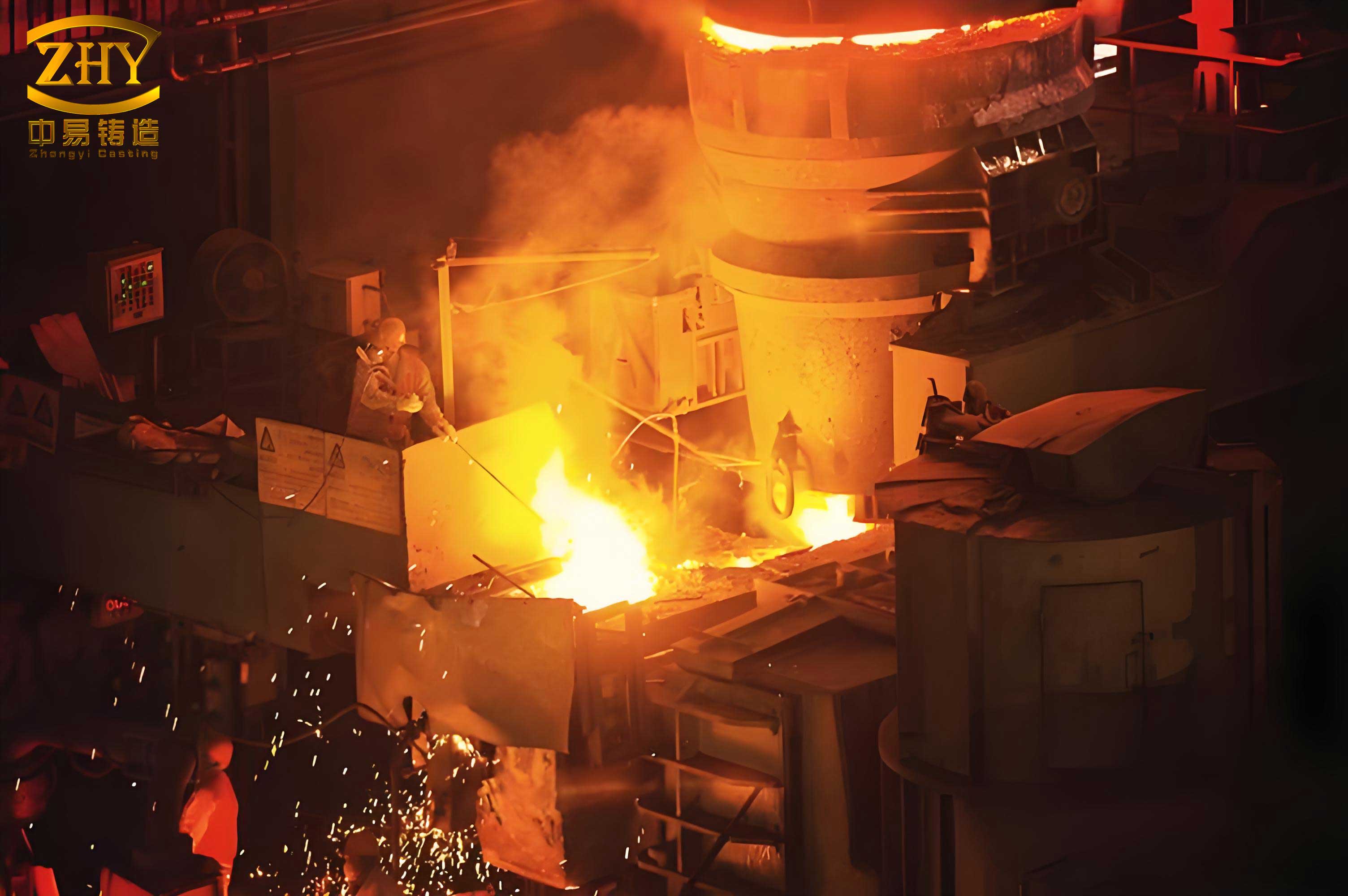
Traditionally, filling speed was managed through empirical methods and operator experience, often leading to inconsistencies. Modern approaches involve simulation software to predict flow patterns and optimize gating system design. However, the real-time control of the pouring process to maintain a preset filling speed profile has seen increasing interest. While Proportional-Integral (PI) controllers have been applied, their performance can be limited by the non-linear and time-varying nature of the casting process. This analysis explores and advocates for the implementation of a Programmable Logic Controller (PLC)-based control system to minimize filling speed error in the sand casting of machine tool beds. Through mathematical modeling, system design, and comparative simulation, I will demonstrate the superior capability of PLC control in ensuring a stable, predictable filling phase, thereby enhancing the quality and reliability of the produced sand castings.
The Sand Casting Process for Machine Tool Beds
The manufacturing of a machine tool bed via sand casting is a multi-step sequence where precision at each stage dictates the success of the final product. The process is meticulously designed to create a robust, dimensionally accurate, and defect-free casting. The core stages are outlined in the table below, which provides a systematic overview of the workflow specific to producing large sand castings like bed frames.
| Process Stage | Key Activities | Objective & Outcome |
|---|---|---|
| 1. Pattern & Core Making | Design and fabrication of a physical pattern (often oversized to account for shrinkage) and sand cores using resin-bonded sand. | To create the negative impression of the final part (mold cavity) and define internal geometries. The pattern shape directly dictates the geometry of the sand castings. |
| 2. Molding | Packing specially formulated molding sand around the pattern within a flask. The pattern is then removed, leaving a precise cavity. | To form the primary mold capable of withstanding the thermal and metallostatic pressure of the molten metal during pouring of sand castings. |
| 3. Core Setting & Mold Assembly | Placing the fabricated cores into the mold cavity and assembling cope and drag sections of the mold. | To complete the internal and external geometry definition before the metal is introduced into the sand castings mold. |
| 4. Pouring & Filling | Transferring molten metal from the furnace into the mold cavity through a designed gating system. | To completely fill the mold cavity with liquid metal. This is the critical phase where filling speed control is paramount for quality sand castings. |
| 5. Solidification & Cooling | Allowing the molten metal to lose heat and solidify completely within the sand mold. | To achieve the final metallic structure. Controlled cooling is vital to minimize residual stresses in large sand castings. |
| 6. Shakeout & Cleaning | Breaking away the sand mold and removing the casting, followed by cutting off gates, risers, and surface cleaning. | To separate the raw casting from the mold material, initiating the post-casting processing of sand castings. |
| 7. Heat Treatment & Finishing | Applying thermal processes (e.g., stress relieving, normalizing) and final machining to critical surfaces. | To achieve the desired mechanical properties and dimensional tolerances required for the machine tool bed application. |
The heart of the process, from a fluid dynamics and control perspective, is Stage 4: Pouring & Filling. The design of the gating system (including pouring basin, sprue, runners, and gates) is initially calculated based on fluid mechanics principles to aim for a desired filling speed. However, during actual operation, factors such as varying metal head pressure, temperature-dependent viscosity, and partial clogging can cause deviations. This is where active control systems intervene to regulate the flow, ensuring the actual filling speed adheres closely to the predetermined optimal profile for producing sound sand castings.
Mathematical Modeling of Filling Speed in Sand Castings
To design an effective control system, a fundamental understanding of the physics governing the flow is necessary. The filling process in sand castings can be analyzed using principles from fluid mechanics, particularly Bernoulli’s equation, applied to the gating system. The primary driving force is the metallostatic pressure head from the height of the metal in the pouring basin and sprue.
The basic relationship between the pressure head and the outlet velocity at the ingate (the entry to the mold cavity) is given by the simplified Bernoulli equation, accounting for energy losses:
$$H = \frac{\nu^2}{2g} + h_{loss}$$
Where:
\( H \) is the effective metallostatic head height (m),
\( \nu \) is the velocity of the molten metal at the ingate outlet (m/s),
\( g \) is the acceleration due to gravity (9.81 m/s²),
\( h_{loss} \) is the total head loss due to friction and form drag in the gating system (m).
The head loss \( h_{loss} \) is typically expressed as a function of the velocity head, incorporating a loss coefficient \( \lambda \) that encapsulates the geometry and roughness of the gating channels:
$$h_{loss} = \lambda \frac{\nu^2}{2g}$$
Substituting Equation (2) into Equation (1) allows us to solve for the theoretical ingate velocity:
$$H = \frac{\nu^2}{2g} (1 + \lambda)$$
$$\nu = \sqrt{\frac{2gH}{1+\lambda}}$$
Equation (4) is crucial as it defines the theoretical filling speed at the point of entry into the mold cavity. The loss coefficient \( \lambda \) is a key parameter that must be empirically determined or estimated for a specific gating system design in sand castings.
Furthermore, the flow rate or the weight of metal delivered into the cavity below the ingate level can be derived. Assuming a constant ingate cross-sectional area \( A \) and metal density \( \rho \), the weight \( G \) of metal flowing into the lower cavity over a time \( t \) is:
$$G = \rho A \nu t = \rho A t \sqrt{\frac{2gH}{1+\lambda}}$$
However, this model represents a steady-state, simplified scenario. In reality, for sand castings with complex geometries like a machine tool bed, the filling is transient. The effective head \( H \) decreases as the mold fills above the ingate level, making \( \nu \) time-dependent. A more generalized form of the filling speed \( v(t) \) considering a time-varying head \( H(t) \) is:
$$v(t) = \mu \sqrt{2g H(t)}$$
Where \( \mu \) is the discharge coefficient ( \( \mu = 1/\sqrt{1+\lambda} \) ), which is always less than 1. The function \( H(t) \) depends on the geometry of the casting and the flow rate history. This time-dependent relationship highlights the need for a control system that can dynamically adjust an input variable (like a stopper rod position or pouring basin tilt) to compensate for the changing \( H(t) \) and maintain \( v(t) \) at a constant desired value, thereby ensuring uniform and controlled filling of sand castings.
Design of a PLC-Based Control System for Filling Speed
To translate the theoretical need for constant filling speed into practical action, a robust, automated control system is designed. A Programmable Logic Controller (PLC) is ideally suited for this industrial environment due to its reliability, real-time processing capability, modularity, and resistance to harsh conditions like heat and vibration prevalent in foundries.
The core objective of the PLC system is to measure the actual filling speed in real-time, compare it with a pre-set target speed, and automatically adjust the pouring mechanism to minimize the error. The system configuration is built around a central PLC CPU module with specialized input/output modules.
System Architecture and Hardware Configuration
The measurement and control loop is implemented as follows. The primary controlled variable is the filling speed. This is indirectly measured by monitoring the flow rate of metal entering the mold. A turbine flow meter is installed in the metal delivery system (e.g., in the runner or a dedicated monitoring bypass). As metal flows, the turbine rotates, and an attached rotary encoder generates a pulse train. The frequency of this pulse train is directly proportional to the volumetric flow rate \( Q \).
The PLC’s high-speed counter input module is connected to this encoder. The PLC program continuously reads the pulse count over a fixed, short time interval \( \Delta t \) to calculate the instantaneous flow rate \( Q_{inst} \). Knowing the cross-sectional area \( A_{choke} \) at a controlled choke point, the filling speed \( v_{inst} \) is computed:
$$v_{inst} = \frac{Q_{inst}}{A_{choke}}$$
This calculated \( v_{inst} \) is the process variable (PV). The operator inputs the desired setpoint filling speed \( v_{set} \) via a human-machine interface (HMI). The PLC’s CPU executes a control algorithm (e.g., a finely tuned PID algorithm) to compute the required adjustment to the final control element.
The control output is typically an analog signal (e.g., 4-20 mA or 0-10 V) sent from the PLC’s analog output module. This signal drives an actuator—most commonly an electric or hydraulic servo controlling a stopper rod mechanism positioned at the bottom of the pouring ladle or an automatic tilting mechanism for the furnace/pouring basin. The actuator’s position regulates the opening size, thereby controlling the metal flow rate to achieve \( v_{inst} = v_{set} \).
| Module Type | Example Model | Function in the Control System |
|---|---|---|
| Central Processing Unit (CPU) | CQM1-CPU41 | Executes the control program, performs calculations (error, PID), and manages data flow between all modules. |
| Digital Input Module | D212 | Reads status from manual control buttons (Start, Stop, Emergency), limit switches, and system ready signals. |
| High-Speed Counter Module | CT021 | Accurately counts high-frequency pulses from the rotary encoder on the flow meter to determine flow rate. |
| Analog Output Module | DA021 | Converts the digital control signal from the CPU to an analog voltage/current to command the stopper rod actuator. |
| Digital Output Module | OD212 / OC22 | Switches peripheral devices: OD212 for status LEDs/display drivers, OC22 for relays controlling pumps or alarms. |
| Power Supply Module | PS02 | Provides stable DC power to the PLC backplane and all connected I/O modules. |
Software Design and Control Logic
The PLC software is structured into two main segments: the control program (often written in ladder logic or structured text) and the HMI interface program. The control program’s logic flow for managing sand castings filling is cyclical:
- Initialization: Check system status, reset counters, and wait for “Cycle Start” command.
- Measurement: Read the high-speed counter value, calculate instantaneous flow rate \( Q_{inst} \) and filling speed \( v_{inst} \).
- Error Calculation: Compute the error \( e(t) = v_{set} – v_{inst} \).
- Control Action: Execute the PID control algorithm:
$$u(t) = K_p e(t) + K_i \int_0^t e(\tau) d\tau + K_d \frac{de(t)}{dt}$$
where \( u(t) \) is the control output signal sent to the analog output module. - Output & Update: Send the computed \( u(t) \) to the actuator. Update the HMI display with \( v_{set} \), \( v_{inst} \), and system status.
- Loop: Return to step 2 at a high frequency (e.g., every 10-100 ms) until the pouring cycle is complete, ensuring continuous, real-time adjustment for optimal sand castings production.
The HMI provides visualization, allowing operators to set parameters, monitor real-time trends of filling speed, and acknowledge alarms, making the process of creating sand castings more transparent and manageable.
Simulation and Comparative Analysis of Control Performance
To validate the effectiveness of the proposed PLC-based control strategy versus a conventional PI controller, a dynamic simulation model is developed in a technical computing environment like MATLAB/Simulink. The simulation incorporates the time-dependent filling dynamics of a machine tool bed mold, the non-linear flow characteristics of the gating system, and the response models of the sensor and actuator.
Simulation Model Parameters
The simulation is configured with parameters representative of a typical gray iron machine tool bed casting produced via sand castings. Key thermal, physical, and process parameters are defined as follows:
| Parameter | Symbol | Value | Unit |
|---|---|---|---|
| Pouring Temperature | \( T_{pour} \) | 1400 | °C |
| Metal Density | \( \rho \) | 7.0 × 10³ | kg/m³ |
| Metal Specific Heat | \( C_p \) | 850 | J·kg⁻¹·K⁻¹ |
| Metal Thermal Conductivity | \( k_{metal} \) | 47.2 | W·m⁻¹·K⁻¹ |
| Target Filling Time | \( t_{fill} \) | 10 | s |
| Mold Heat Transfer Coefficient | \( h \) | 155 | W·m⁻²·K⁻¹ |
| Solidification Contraction | \( \beta \) | 1.5 | % |
| Target Filling Speed | \( v_{set} \) | 0.15 | m/s |
The simulation runs a complete filling cycle. Disturbances are introduced to mimic real-world conditions, such as a ±10% variation in the effective metallostatic head due to uneven ladle emptying and random minor fluctuations in metal viscosity.
Simulation Results: PLC vs. PI Control
The performance metric is the filling speed error \( e(t) = v_{set} – v_{actual}(t) \) over the entire pouring duration. The results from the simulation clearly differentiate the two control strategies.
1. PLC Control Performance: The PLC-based system, with its fast scan cycle, precise digital filtering of the encoder signal, and a well-tuned control algorithm, demonstrates excellent performance. The simulation shows that the actual filling speed rapidly converges to the setpoint after the initial pour command. Throughout the filling process, the system actively compensates for the decreasing head pressure and other disturbances. The resulting error \( e(t) \) remains tightly bounded within a very small band. The maximum absolute error observed in the simulation is on the order of \( 1.8 \times 10^{-4} \) m/s. This represents an error of merely about 0.12% of the setpoint speed. The filling process is smooth and stable, leading to a laminar, progressive front advancement within the mold cavity—the ideal condition for producing high-quality sand castings free from turbulence-related defects.
2. Conventional PI Control Performance: In contrast, the simulated conventional PI controller, while functional, shows significant limitations. Its analog nature and slower response time lead to pronounced oscillations during the initial transient phase. More critically, it struggles to adapt perfectly to the continuously changing process dynamics (the time-varying \( H(t) \)). The error \( e(t) \) exhibits larger amplitude fluctuations throughout the cycle. The simulation records a maximum absolute error of approximately \( 3.6 \times 10^{-2} \) m/s, which is 200 times greater than the PLC error and constitutes about 24% of the setpoint speed. This instability in filling speed can cause variations in the thermal history across different sections of the casting during the critical initial filling moments, potentially promoting localized stress concentration and increasing the risk of surface defects in the final sand castings.
The stark contrast in performance is summarized in the table below, highlighting why PLC control is superior for this demanding application in sand castings production.
| Performance Metric | PLC-Based Control | Conventional PI Control |
|---|---|---|
| Maximum Absolute Error | ~ \( 1.8 \times 10^{-4} \) m/s | ~ \( 3.6 \times 10^{-2} \) m/s |
| Error as % of Setpoint | ~ 0.12 % | ~ 24 % |
| Response to Disturbances | Fast, precise correction with minimal overshoot. | Slower, corrective actions often lead to oscillation and steady-state offset. |
| Filling Speed Stability | Highly stable; near-constant speed maintained. | Unstable; significant speed fluctuations occur. |
| Implied Casting Quality | Promotes laminar flow, uniform thermal gradients, minimized stress, and high surface integrity in sand castings. | Risk of turbulent flow, uneven cooling, stress concentration, and surface defects like cracks in sand castings. |
| System Flexibility | High. Control logic, setpoints, and tuning parameters can be easily modified via software for different sand castings designs. | Low. Changes require hardware rewiring or component replacement. |
Conclusion
The pursuit of excellence in manufacturing critical components like machine tool beds demands precision at every stage of production. In the realm of sand castings, the control of the molten metal filling speed is a decisive factor influencing the internal soundness and surface quality of the final product. This analysis has systematically detailed the application of an advanced PLC-based control system to master this variable.
Beginning with a review of the sand casting process, I established the context for why controlled filling is vital. Through the derivation of fundamental fluid flow equations, I provided the theoretical foundation linking pressure head to filling velocity. The design and implementation of a dedicated PLC control system were then elaborated, showcasing its hardware robustness and software adaptability for the harsh foundry environment. The core of the argument was substantiated through dynamic simulation, which provided a clear, quantitative comparison between the proposed PLC control and a traditional PI control method.
The results are unequivocal. The PLC-based system achieves a remarkable reduction in filling speed error—by two orders of magnitude in the simulated scenario—ensuring a stable, predictable fill. This level of control directly translates to tangible benefits in the production of sand castings: it minimizes turbulent flow, promotes uniform solidification, avoids harmful thermal stresses, and significantly reduces the incidence of defects such as cold shuts, mistruns, and surface cracks. Consequently, the mechanical performance, dimensional accuracy, and overall reliability of the machine tool bed are enhanced.
Therefore, the integration of programmable logic control into the pouring phase of sand castings represents a significant technological advancement. It moves the process from empirical estimation towards a data-driven, automated, and repeatable standard. For foundries aiming to produce high-value, large-scale, and complex sand castings with consistent quality, investing in such a PLC-controlled filling system is not just an optimization but a strategic imperative for competitiveness and excellence in modern manufacturing.