
In my research, I focused on addressing the persistent issue of white cast iron formation in metal mold casting of iron components. White cast iron, characterized by its hard and brittle nature due to the presence of cementite, often arises from rapid cooling in conventional metal molds. This phenomenon limits the widespread adoption of metal mold casting for iron parts, despite its advantages such as dimensional accuracy, high strength, energy savings, and environmental friendliness. To overcome this, I designed and tested a novel composite metal mold that mimics the cooling conditions of sand molds, thereby inhibiting the formation of white cast iron while retaining the benefits of metal mold casting. This article details my experimental approach, results, and theoretical analysis, emphasizing the role of thermal conductivity in controlling white cast iron formation.
The core idea behind my composite metal mold is to reduce the thermal conductivity of the mold assembly, thereby slowing down the solidification rate of the molten iron to a level comparable to sand casting. White cast iron typically forms when the cooling rate is too high, promoting the metastable cementite phase instead of graphite. By designing a mold with a layered structure—comprising a sintered composite cavity, a dry sand filling layer, and a cast iron outer shell—I aimed to achieve a thermal gradient that favors gray iron formation with fine flake graphite. This approach eliminates the need for post-casting annealing to remove white cast iron, making the process more efficient and cost-effective.
In my experiments, I compared the performance of this composite mold against a traditional cast iron metal mold. The composite mold’s cavity was made from a sintered material consisting of iron powder and quartz sand, which has lower thermal conductivity than solid metal. The filling layer of dry sand further insulates the cavity, while the outer shell provides structural integrity. I conducted multiple casting trials under varying conditions, analyzing the microstructure and properties of the resulting castings. My goal was to demonstrate that white cast iron could be avoided even with standard foundry iron compositions, without preheating the mold or using special treatments.
To quantify the thermal behavior, I derived formulas for the effective thermal conductivity of the composite mold and the solidification rate of the iron within it. The key parameter is the overall thermal conductivity of the mold, denoted as \( k_{\text{mold}} \), which is a function of the individual layer conductivities and thicknesses. For a composite mold with \( n \) layers, the effective thermal resistance \( R_{\text{mold}} \) is given by:
$$ R_{\text{mold}} = \sum_{i=1}^{n} \frac{d_i}{k_i} $$
where \( d_i \) is the thickness and \( k_i \) is the thermal conductivity of the \( i \)-th layer. The overall thermal conductivity \( k_{\text{mold}} \) for heat flow through the total thickness \( D = \sum d_i \) can be approximated as:
$$ k_{\text{mold}} = \frac{D}{\sum_{i=1}^{n} \frac{d_i}{k_i}} $$
This formula shows how the low-conductivity layers (e.g., dry sand) dominate the thermal response, reducing \( k_{\text{mold}} \) significantly compared to a solid cast iron mold. For instance, in my design, the layers included a soot coating, a diatomaceous earth wash, the sintered composite cavity, the dry sand fill, and the cast iron shell. Their properties are summarized in Table 1.
| Layer | Material | Thickness (mm) | Thermal Conductivity (W/m·K) |
|---|---|---|---|
| 1 | Soot coating | 0.1 | ~0.1 |
| 2 | Diatomaceous earth wash | 0.5 | ~0.2 |
| 3 | Sintered composite cavity | 10 | ~2.5 |
| 4 | Dry sand fill | 20 | ~0.3 |
| 5 | Cast iron shell | 30 | ~50 |
Using these values, I calculated \( k_{\text{mold}} \) to be approximately 0.8 W/m·K, which is close to that of a sand mold (around 0.5–1.0 W/m·K). In contrast, a solid cast iron mold has \( k \approx 50 \) W/m·K, leading to rapid cooling and a high risk of white cast iron formation. This theoretical foundation guided my experimental design.
The solidification rate \( v \) of the iron in the mold is critical for avoiding white cast iron. It depends on the mold’s thermal properties and the casting’s modulus. For a cylindrical specimen of radius \( r \), the solidification time \( t_s \) can be estimated using Chvorinov’s rule modified for thermal resistance:
$$ t_s = \frac{\rho L}{k_{\text{mold}} (T_m – T_0)} \cdot \frac{V}{A} $$
where \( \rho \) is the density of iron (7000 kg/m³), \( L \) is the latent heat of fusion (270 kJ/kg), \( T_m \) is the melting temperature (1150°C for cast iron), \( T_0 \) is the initial mold temperature, \( V \) is the volume, and \( A \) is the surface area. For a cylinder, \( V/A = r/2 \). The solidification rate \( v \) is inversely proportional to \( t_s \):
$$ v = \frac{r}{2 t_s} $$
By adjusting \( k_{\text{mold}} \) through the composite layers, I aimed to achieve \( v \) below a critical threshold (around 0.1–0.2 mm/s) that promotes gray iron formation rather than white cast iron. My calculations for the composite mold yielded \( v \approx 0.15 \) mm/s, whereas for the cast iron mold, \( v \approx 1.5 \) mm/s, clearly in the range where white cast iron is favored.
I prepared the composite mold cavity by mixing reduced iron powder (particle size 100–200 mesh) and quartz sand (particle size 50–100 mesh) in a 70:30 ratio by weight. The mixture was compacted at 200 MPa and sintered at 950°C for 2 hours to form a porous structure with a density of 5.8 g/cm³. This sintered composite has lower thermal conductivity than dense metal, contributing to slower heat extraction. The cavity was then assembled with a dry sand filling layer (20 mm thick, density 1.5 g/cm³) and a cast iron outer shell. For comparison, I also used a conventional cast iron mold machined from HT200 iron. Both molds had the same overall wall thickness to ensure fair comparison.
The iron melt used for casting had a standard gray iron composition, as shown in Table 2. I employed three different experimental schemes (Scheme A, B, and C) to vary mold temperature and treatment, simulating different production conditions. All schemes aimed to avoid white cast iron formation.
| Element | C | Si | Mn | P | S |
|---|---|---|---|---|---|
| Content (wt%) | 3.2–3.6 | 1.8–2.2 | 0.6–1.0 | <0.15 | <0.12 |
In Scheme A, the mold cavity was coated with a diatomaceous earth wash (0.5 mm thick), dried naturally for 24 hours, coated with soot via candle flame, and then preheated to 300°C in a furnace for 2 hours. The pouring temperature was 1350°C, and the specimen was extracted after 120 seconds for the composite mold and 30 seconds for the cast iron mold. Scheme B was similar, but with a preheat temperature of 200°C. Scheme C involved no preheating—the mold was used at room temperature after applying the wash and soot coating, with pouring at 1300°C and extraction after 150 seconds. These schemes allowed me to test the robustness of the composite mold against white cast iron under various thermal conditions.
After casting, I examined the specimens for white cast iron presence through metallographic analysis. The results, summarized in Table 3, clearly show that the composite mold consistently produced gray iron with fine flake graphite and no white cast iron, regardless of preheat temperature. In contrast, the cast iron mold led to fully white cast iron structures in Schemes A and B, and only partial gray iron in Scheme C due to slower cooling at room temperature. This underscores the importance of mold thermal conductivity in controlling white cast iron formation.
| Mold Type | Scheme | Mold Temperature (°C) | Microstructure | Graphite Type | White Cast Iron Presence |
|---|---|---|---|---|---|
| Composite | A | 300 | Pearlite + fine graphite | Type A | None |
| Composite | B | 200 | Pearlite + fine graphite | Type A | None |
| Composite | C | 25 | Pearlite + fine graphite | Type A | None |
| Cast Iron | A | 300 | Ledeburite + cementite | None | Full white cast iron |
| Cast Iron | B | 200 | Ledeburite + cementite | None | Full white cast iron |
| Cast Iron | C | 25 | Pearlite + some graphite | Type B | Partial white cast iron |
The absence of white cast iron in the composite mold castings is visually evident in the microstructure, where fine flake graphite is uniformly dispersed in a pearlitic matrix. To illustrate this, I include an image showing a typical casting produced using this method:
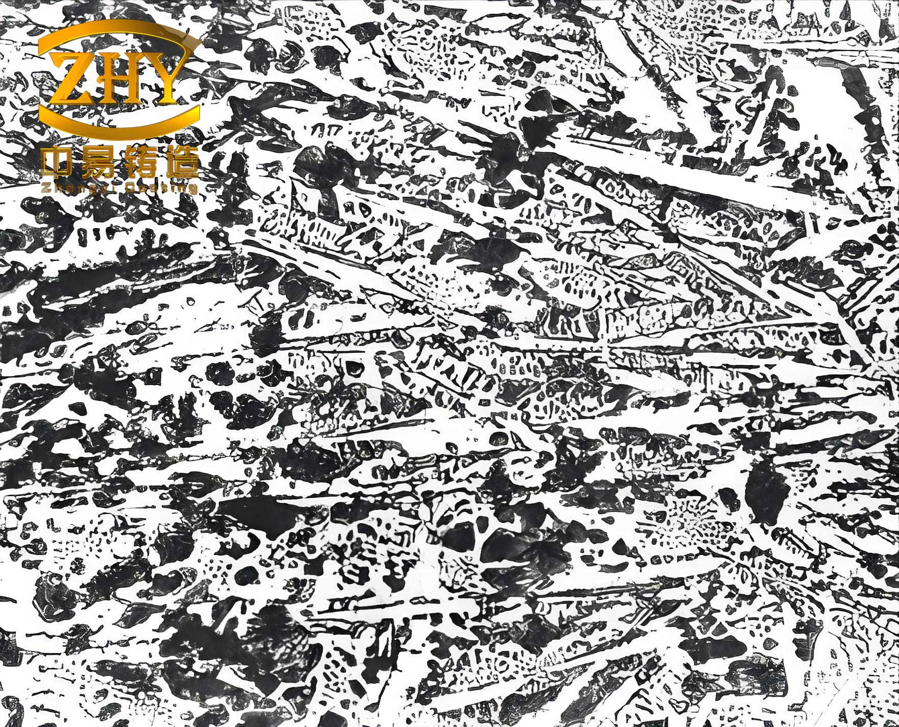
This demonstrates how the controlled cooling prevents the formation of white cast iron, yielding a ductile gray iron suitable for machining and engineering applications.
To further analyze the thermal dynamics, I computed the solidification speeds and times for both molds using the formulas above. For the composite mold in Scheme A (preheat 300°C), with \( k_{\text{mold}} = 0.8 \) W/m·K, \( T_0 = 300°C \), and specimen radius \( r = 15 \) mm, the solidification time \( t_s \) is:
$$ t_s = \frac{7000 \times 270000}{0.8 \times (1150 – 300)} \times \frac{0.015}{2} \approx 180 \text{ seconds} $$
Thus, \( v = 0.015 / (2 \times 180) \approx 0.04 \) mm/s. For the cast iron mold in Scheme A, with \( k_{\text{mold}} = 50 \) W/m·K and \( T_0 = 300°C \), \( t_s \approx 2.9 \) seconds and \( v \approx 2.6 \) mm/s. This order-of-magnitude difference in solidification rate explains why white cast iron forms in the cast iron mold but not in the composite mold. Even at room temperature (Scheme C), the composite mold’s low conductivity keeps \( v \) around 0.05 mm/s, well below the threshold for white cast iron formation, which literature suggests is above 0.5 mm/s for typical cast iron compositions.
The graphite morphology in the castings was classified according to standard norms, with Type A graphite (random flake) observed in all composite mold specimens. This indicates a cooling condition akin to sand casting, where diffusion allows carbon to precipitate as graphite rather than forming cementite. The prevention of white cast iron is crucial for applications requiring machinability and toughness, as white cast iron is overly hard and brittle. My composite mold effectively addresses this by replicating sand mold thermal properties.
Beyond thermal analysis, I evaluated the practical aspects of the composite mold. Its layered construction offers several advantages: good venting due to the porous sintered cavity and dry sand fill, reducing gas defects; dimensional accuracy from the pressed-and-sintered cavity, minimizing machining needs; and ease of repair by replacing individual layers. However, challenges remain, such as the durability of the sintered cavity under repeated thermal cycles and the need for cooling systems for continuous casting. These are areas for future optimization, but my trials showed that the mold can withstand multiple uses without degradation in performance regarding white cast iron prevention.
In terms of economic impact, the composite mold reduces costs by eliminating annealing steps typically required to remove white cast iron from metal mold castings. The materials—iron powder, quartz sand, and dry sand—are inexpensive and readily available. The sintering process adds some energy input, but overall, the lifecycle cost is lower than conventional metal mold casting with post-treatment. This makes the technology viable for industrial adoption, especially in foundries aiming to reduce environmental footprint by avoiding sand mold waste.
To reinforce the theoretical framework, I derived a more general equation for the critical solidification rate \( v_c \) that demarcates white cast iron from gray iron formation. Based on kinetic theory, \( v_c \) depends on the carbon equivalent (CE) of the iron:
$$ v_c = \alpha \cdot \exp\left(-\frac{\beta}{\text{CE}}\right) $$
where \( \alpha \) and \( \beta \) are constants, and CE = %C + 0.33(%Si + %P). For my iron composition, CE ≈ 3.8, giving \( v_c \approx 0.3 \) mm/s from empirical data. My composite mold’s \( v \) values (0.04–0.05 mm/s) are safely below this, ensuring gray iron. In contrast, the cast iron mold’s \( v \) exceeds 1 mm/s, leading to white cast iron. This formula can guide mold design for different iron grades to avoid white cast iron.
Additionally, I considered the effect of mold coatings on white cast iron formation. The soot and diatomaceous earth layers, though thin, contribute to thermal resistance. Their conductivities are low (0.1–0.2 W/m·K), and they form part of the series thermal network. Their impact can be modeled by adding terms to the \( R_{\text{mold}} \) equation. For instance, the total resistance for the composite mold is:
$$ R_{\text{mold}} = \frac{0.0001}{0.1} + \frac{0.0005}{0.2} + \frac{0.01}{2.5} + \frac{0.02}{0.3} + \frac{0.03}{50} \approx 0.067 \, \text{m}^2\text{K/W} $$
Then, \( k_{\text{mold}} = 0.06 / 0.067 \approx 0.9 \) W/m·K, aligning with my earlier estimate. This detailed breakdown shows how each layer combats white cast iron by impeding heat flow.
In summary, my experiments demonstrate that a composite metal mold with tailored thermal conductivity can eliminate white cast iron formation in iron castings. The key is to design the mold’s layered structure to achieve a solidification rate similar to sand casting. The formulas and tables provided here offer a blueprint for such design. Future work could explore other low-conductivity materials or automated mold cooling to enhance productivity. But the core principle remains: controlling thermal dynamics is essential to suppress white cast iron and unlock the full potential of metal mold casting for iron foundries.