
The continuous growth in electricity demand, particularly in eastern coastal regions of China, coupled with the concentration of energy resources in the western provinces, has necessitated the development of long-distance, high-voltage power transmission corridors. Overhead transmission lines are the primary means for this power transfer. However, these lines often traverse through regions prone to strong winds and sandstorms. The resultant dynamic swinging of line fittings, such as connectors and clamps, leads to severe frictional wear. Traditionally, these fittings are manufactured from medium-carbon steels like 40Cr or 35CrMo and protected by hot-dip galvanizing. In harsh wind-sand environments, this soft zinc coating is prone to rapid abrasion and detachment, leaving the substrate vulnerable to corrosion and accelerating failure. This compromises grid stability and increases maintenance costs. Therefore, developing new materials with inherent wear and corrosion resistance for transmission line fittings is an urgent engineering challenge.
Spheroidal graphite cast iron presents a promising alternative. During frictional wear, the graphite nodules within its matrix can act as solid lubricants, forming a protective film that reduces the coefficient of friction and wear rate. Austempering, a specific heat treatment, further enhances the properties of spheroidal graphite cast iron, transforming it into Austempered Ductile Iron (ADI). ADI possesses a unique microstructure of acicular ferrite (bainitic ferrite) within a carbon-enriched retained austenite matrix, known as ausferrite. This structure offers an excellent combination of high strength, good toughness, and superior wear resistance compared to quenched and tempered martensitic structures of similar hardness.
The performance of spheroidal graphite cast iron is highly sensitive to its chemical composition and heat treatment parameters. Silicon (Si) is a pivotal element; it is a strong graphitizer, promotes ferrite formation, and suppresses carbide precipitation during austempering, which is crucial for achieving the desired tough ausferrite microstructure. Conventional spheroidal graphite cast iron typically contains around 3 wt.% Si, which increases strength but can reduce ductility. Reducing the Si content to approximately 1 wt.% is known to improve ductility. Copper (Cu) and Phosphorus (P) are often added to improve atmospheric corrosion resistance, with a synergistic effect observed when both are present. Copper can also enhance nodule count and roundness. However, the combined effect of lowered Si content with the addition of Cu and P on the microstructure and, more importantly, on the mechanical properties after austempering is not thoroughly documented.
This work aims to systematically investigate the influence of Si, Cu, and P contents, along with austempering temperature, on the microstructure and mechanical properties of spheroidal graphite cast iron. The goal is to develop a grade suitable for high-wear, corrosion-prone applications like transmission line fittings. The primary objectives are:
- To study the as-cast microstructure of spheroidal graphite cast iron with varying Si, Cu, and P levels.
- To examine the evolution of the ausferritic microstructure after austempering at different temperatures (260°C, 300°C, 380°C).
- To correlate the composition and microstructure with key mechanical properties: hardness, yield strength, tensile strength, and elongation.
- To elucidate the strengthening and toughening mechanisms imparted by the alloying elements and the austempering process.
1. Literature Review and Theoretical Background
1.1 Fundamentals of Spheroidal Graphite Cast Iron
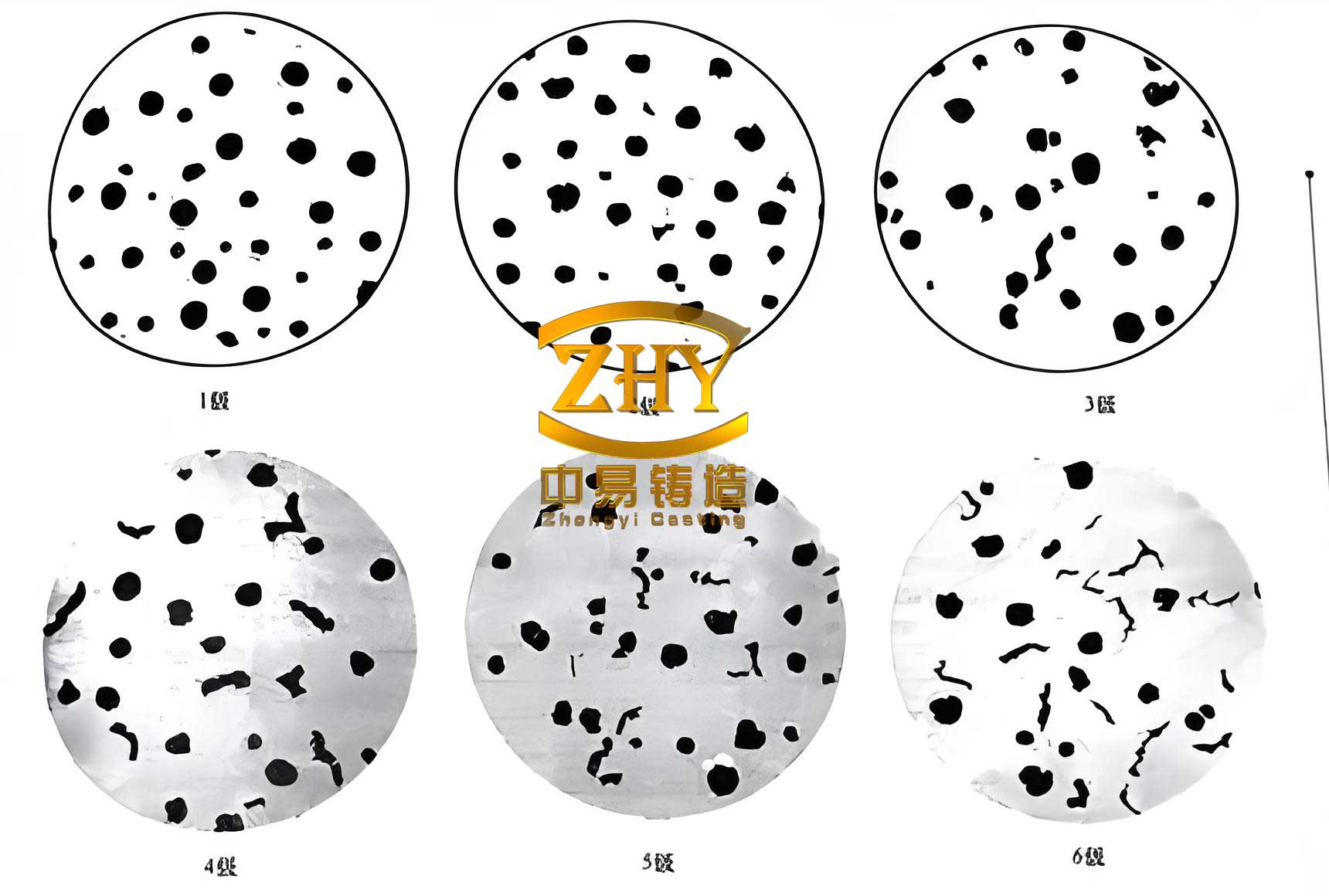
Spheroidal graphite cast iron, or ductile iron, is characterized by its graphite morphology, where the carbon precipitates as spheres rather than flakes. This is achieved through the addition of nodulizing elements, typically magnesium or cerium, during molten metal treatment. The spherical shape minimizes the stress-concentrating effect of graphite, granting the material much higher ductility and toughness compared to gray iron. The matrix can be tailored through composition and heat treatment to be ferritic, pearlitic, martensitic, or ausferritic. The carbon equivalent (CE) is a critical parameter for predicting solidification behavior and is calculated as:
$$ CE = w(C) + \frac{1}{3}w(Si + P) $$
where w(C), w(Si), and w(P) are the weight percentages of carbon, silicon, and phosphorus, respectively. A CE near 4.3 indicates a eutectic composition, which is favorable for graphite formation.
1.2 Role of Alloying Elements
Silicon (Si): Si is a ferrite stabilizer and a potent graphitizer. It increases the activity of carbon in molten iron, favoring graphite nucleation over cementite (Fe3C). During solid-state transformations, Si strongly inhibits the formation of carbides, which is essential for obtaining carbide-free bainitic (acicular ferrite) structures in ADI. It also provides solid solution strengthening in ferrite.
Copper (Cu): Cu is a mild graphitizer and tends to partition into the austenite phase during solidification and heat treatment. It enhances hardenability and can improve corrosion resistance. Studies suggest Cu enrichment at graphite/matrix interfaces may refine graphite nodules.
Phosphorus (P): P has limited solubility in ferrite and tends to segregate at grain boundaries, potentially forming hard, brittle phosphide eutectics (steadite) which can be detrimental to toughness. However, in small amounts and in combination with Cu, it contributes to atmospheric corrosion resistance.
The interaction of these elements in a low-Si spheroidal graphite cast iron system designed for austempering needs detailed investigation.
1.3 Austempering of Spheroidal Graphite Cast Iron
Austempering involves austenitizing the spheroidal graphite cast iron followed by rapid quenching to an intermediate temperature (typically between 250°C and 400°C) in a salt bath, holding isothermally, and then air cooling. This process bypasses the pearlite and martensite transformation regions. The isothermal holding allows for the diffusion-controlled transformation of austenite into acicular ferrite and high-carbon austenite. The reaction is often described in two stages:
Stage I: Austenite (γ) → Acicular Ferrite (α) + High-C Austenite (γHC)
Stage II: High-C Austenite (γHC) → Ferrite (α) + Carbide (unwanted)
The goal is to complete Stage I but avoid Stage II, as carbide formation embrittles the material. Si plays a crucial role in retarding Stage II. The final microstructure, ausferrite, consists of fine, acicular ferrite laths interlaced with films of thermally stable, carbon-enriched retained austenite. The proportions, size, and carbon content of these phases determine the final properties. Higher austempering temperatures generally lead to coarser ferrite, higher retained austenite volume, and lower strength but improved ductility and toughness.
2. Experimental Methodology
2.1 Material Preparation and Composition
To achieve a eutectic composition while varying Si content, the carbon level was adjusted accordingly. Three distinct grades of spheroidal graphite cast iron were prepared via horizontal continuous casting. The raw materials (steel scrap, pig iron) were melted in a medium-frequency induction furnace. Alloying additions of aluminum, copper, ferrophosphorus, and ferrosilicon were made to the molten iron. After thorough melting, the melt was treated using a wire-feeding method for nodulization and inoculation. The chemical compositions of the three experimental spheroidal graphite cast iron grades, designated as Grade 1, Grade 2, and Grade 3, are detailed in Table 1.
| Grade | C | Si | Cu | P | Fe | CE |
|---|---|---|---|---|---|---|
| 1 | 3.1 | 2.9 | 0 | 0 | Bal. | 4.1 |
| 2 | 4.4 | 1.1 | 0 | 0 | Bal. | 4.8 |
| 3 | 4.4 | 1.1 | 0.6 | 0.1 | Bal. | 4.8 |
2.2 Heat Treatment (Austempering)
All specimens were subjected to an austempering heat treatment. The process comprised:
- Austenitizing: Heating to 950°C and holding for 2 hours to achieve a homogeneous, fully austenitic matrix saturated with carbon.
- Quenching: Rapidly transferring the samples to a molten salt bath maintained at one of three different isothermal temperatures: 260°C, 300°C, or 380°C. The salt mixture consisted of 50% NaNO3 and 50% KNO2.
- Isothermal Holding: Holding at the selected temperature for 1.5 hours to allow the austenite to bainitic ferrite transformation (Stage I) to proceed.
- Cooling: Air cooling to room temperature.
2.3 Microstructural Characterization
Samples for metallography were sectioned, mounted, ground, polished, and etched with 4% nital. Microstructural analysis was performed using:
- Optical Microscopy (OM): To observe general microstructure and graphite morphology. Graphite nodule count, size, and inter-nodule spacing were statistically analyzed using image analysis software.
- Scanning Electron Microscopy (SEM): To examine the fine details of the ausferritic microstructure, including the morphology of acicular ferrite and retained austenite.
- X-ray Diffraction (XRD): To identify phases present (e.g., ferrite, austenite, cementite) and to estimate lattice parameters. Scans were conducted from 30° to 85° (2θ). The lattice parameter (a) for the body-centered cubic (BCC) α-Fe phase was calculated from multiple peaks using the formula:
$$ a = d_{hkl} \cdot \sqrt{h^2 + k^2 + l^2} $$
where dhkl is the interplanar spacing for the (hkl) plane. The lattice distortion was calculated relative to pure α-Fe (a = 0.2863 nm).
2.4 Mechanical Testing
- Hardness Testing: Rockwell C-scale (HRC) hardness was measured on the austempered bulk samples. Microhardness (HV0.05) of individual matrix constituents in the as-cast state was also measured.
- Tensile Testing: Room-temperature tensile tests were conducted on dog-bone shaped specimens machined from the austempered materials, according to standard GB/T 228.1. The yield strength (Rp0.2), tensile strength, and total elongation at fracture were determined.
3. Results and Discussion
3.1 As-Cast Microstructure and Phase Constitution
The graphite morphology statistics for the unetched as-cast spheroidal graphite cast iron samples are summarized in Table 2. Grade 1 (high-Si) exhibited the highest nodule count, smallest nodule size, and shortest inter-nodule spacing, indicating superior nucleation and graphite formation. Grade 2 (low-Si, no Cu/P) had the poorest nodularity, with fewer, larger, and more irregularly shaped nodules. The addition of 0.6% Cu and 0.1% P in Grade 3 significantly improved the nodule count and roundness compared to Grade 2, confirming Cu’s beneficial role in graphite formation.
| Grade | Nodule Count (mm-2) | Average Nodule Diameter (µm) | Average Inter-Nodule Spacing (µm) |
|---|---|---|---|
| 1 | 596 ± 15 | 16.1 ± 2.5 | 44.7 ± 6.1 |
| 2 | 112 ± 15 | 35.7 ± 3.3 | 66.0 ± 7.1 |
| 3 | 162 ± 15 | 20.3 ± 3.1 | 55.3 ± 6.5 |
The etched microstructures revealed significant differences in the matrix. Grade 1 showed a fully ferritic matrix surrounding the graphite nodules. This is attributed to the high Si content, which strongly promotes ferrite formation and suppresses pearlite, even at the relatively high carbon equivalent. In contrast, Grades 2 and 3, with low Si content, exhibited a mixed matrix of pearlite, ferrite, and cementite carbides. The microhardness values confirmed this: ferrite (~240-290 HV), pearlite (~420-430 HV), and cementite (~880-1100 HV). XRD analysis (Figure 4 from original text) further confirmed the presence of cementite peaks in Grades 2 and 3 but not in Grade 1.
The lattice constant calculations for the α-Fe phase from XRD data provide insight into solid solution effects (Table 3). Grade 3 (low-Si + Cu/P) exhibited the largest average lattice constant and the highest calculated lattice distortion (0.260%). Grade 1 (high-Si) showed the smallest distortion (0.006%). This indicates that in the low-Si spheroidal graphite cast iron, the added Cu and P atoms cause more significant lattice strain in the ferrite, which would contribute to solid solution strengthening. The increase in lattice constant from Grade 1 to Grade 2 also suggests that lowering Si itself may alter the lattice parameter, possibly due to changes in carbon in solid solution.
| Grade | a(110) (nm) | a(200) (nm) | a(211) (nm) | Average Lattice Constant (nm) | Lattice Distortion vs. Pure Fe (%) |
|---|---|---|---|---|---|
| 1 | 0.2865 | 0.2867 | 0.2865 | 0.2866 | 0.006 |
| 2 | 0.2869 | 0.2873 | 0.2870 | 0.2871 | 0.170 |
| 3 | 0.2874 | 0.2874 | 0.2871 | 0.2873 | 0.260 |
3.2 Microstructural Evolution After Austempering
All three grades of spheroidal graphite cast iron transformed into an ausferritic microstructure after austempering, consisting of acicular ferrite and retained austenite, with no evidence of carbide formation (Stage II reaction) within the matrix, as confirmed by XRD and SEM.
Effect of Austempering Temperature: For all grades, increasing the isothermal temperature from 260°C to 380°C caused a clear microstructural coarsening.
- At 260°C: The undercooling below the bainite start temperature (Bs) is large, resulting in a high driving force for transformation. This leads to a high nucleation rate for acicular ferrite, producing a very fine, densely packed structure with thin ferrite laths. The carbon diffusion rate is relatively low, limiting growth and carbon partitioning, so the retained austenite content is relatively low but potentially less stable.
- At 300°C: The undercooling is moderate. This allows for a good density of ferrite nucleation sites while providing sufficient thermal energy for carbon diffusion. The resulting structure is still fine but with slightly coarsened ferrite laths compared to 260°C. The carbon enrichment of austenite is more effective, leading to a higher volume fraction of stable retained austenite.
- At 380°C: Close to the upper bainite region, the undercooling is small. The nucleation rate for ferrite is low, but the growth rate is high due to fast carbon diffusion. This produces a coarse, plate-like acicular ferrite structure with large pockets of carbon-enriched retained austenite. The microstructure is much more open and less dense.
XRD patterns confirmed the increase in retained austenite peak intensity with increasing temperature for Grades 1 and 3.
Effect of Alloy Composition: At any given austempering temperature, the scale of the ausferrite differed between grades.
- Grade 1 (High-Si): Consistently displayed the finest and most densely distributed acicular ferrite. The high nodule count provided abundant nucleation sites at the graphite/matrix interfaces. Furthermore, Si’s strong suppression of carbide formation ensures a clean ferrite-austenite mixture.
- Grade 2 (Low-Si, no Cu/P): Exhibited a coarser ausferritic structure with larger ferrite laths and wider austenite regions. The lower nodule count reduced nucleation sites, and the lower Si content might slightly reduce the driving force for ferrite nucleation.
- Grade 3 (Low-Si + Cu/P): Showed a microstructure finer than Grade 2 but coarser than Grade 1. The improved nodule count from Cu addition provided more nucleation sites, refining the structure compared to Grade 2. The partitioning of Cu into austenite may also influence transformation kinetics.
The nucleation of acicular ferrite is favored at the graphite/matrix interface due to a low crystallographic misfit. The number density of graphite nodules therefore directly influences the fineness of the ausferrite. The relationship can be conceptually described by considering the nucleation rate (I) which is a function of undercooling (ΔT) and available sites (Nsites), where Nsites is proportional to the nodule count per unit area. A simplified expression is:
$$ I \propto N_{sites} \cdot \exp\left(-\frac{Q}{kT}\right) \cdot \exp\left(-\frac{\Delta G^*}{kT}\right) $$
where Q is an activation energy, k is Boltzmann’s constant, T is temperature, and ΔG* is the critical nucleation energy barrier. Higher nodule counts (Nsites) directly increase I, leading to a finer microstructure.
3.3 Mechanical Properties After Austempering
The mechanical properties of the austempered spheroidal graphite cast iron are summarized in Table 4 and Figure 9 (conceptualized from data).
| Grade | Aust. Temp. (°C) | Hardness (HRC) | Yield Strength, Rp0.2 (MPa) | Total Elongation (%) |
|---|---|---|---|---|
| 1 | 260 | 45.2 | ~1250 | ~3 |
| 300 | 43.7 | ~1320 | ~5 | |
| 380 | 29.9 | ~900 | ~10 | |
| 2 | 260 | 45.1 | ~1150 | ~1.5 |
| 300 | 41.9 | ~1200 | ~3 | |
| 380 | 28.1 | ~750 | ~6 | |
| 3 | 260 | 47.0 | ~1280 | ~2.5 |
| 300 | 41.9 | 1363 | ~4.5 | |
| 380 | 32.8 | ~850 | ~8 |
Effect of Austempering Temperature: The trends are consistent across all grades.
- Hardness: Decreases monotonically with increasing temperature due to microstructural coarsening and increased soft retained austenite content.
- Yield and Tensile Strength: Peak at an intermediate temperature of 300°C. At 260°C, although the structure is very fine, the lower retained austenite content and potentially higher dislocation density in the very fine ferrite might not optimize strength. At 300°C, the combination of a still-fine ferrite structure and a significant amount of strong, film-like retained austenite provides maximum resistance to deformation. At 380°C, coarsening of ferrite laths is the dominant factor, causing a drop in strength.
- Ductility (Total Elongation): Increases steadily with temperature. This is primarily due to the increase in the volume fraction of ductile, metastable retained austenite, which can undergo strain-induced transformation to martensite (TRIP effect), enhancing work hardening and delaying necking.
Effect of Alloy Composition:
- Grade 1 (High-Si): Exhibited the best combination of strength and ductility at all temperatures, especially at 300°C and 380°C. This is a direct consequence of its fine ausferritic structure. The high Si solid solution strengthens the ferrite, and the fine scale provides a high density of interfaces (ferrite/ferrite, ferrite/austenite) that impede dislocation motion. The spherical, well-dispersed graphite minimizes stress concentration, allowing good ductility.
- Grade 2 (Low-Si, no Cu/P): Showed the lowest ductility and moderate strength. The coarse ausferrite offers less strengthening from grain/interface boundaries. More critically, the poor graphite nodularity and larger nodules act as more potent stress raisers, initiating cracks earlier during tensile loading.
- Grade 3 (Low-Si + Cu/P): Demonstrated a remarkable improvement over Grade 2. It achieved the highest yield strength (1363 MPa at 300°C) among all conditions tested. This is attributed to a combination of mechanisms: 1) Solid Solution Strengthening: Cu and P in solid solution (evidenced by lattice distortion) strengthen the ferrite. 2) Microstructural Refinement: The increased nodule count refined the ausferrite compared to Grade 2. 3) Improved Graphite Morphology: Better nodule roundness reduces stress concentration. The ductility of Grade 3 was also significantly better than Grade 2, approaching that of Grade 1 at higher temperatures, due to the combined effect of refined structure and more favorable graphite shape.
The strengthening contribution from solid solution can be approximated using the Labusch-type model for concentrated solutions:
$$ \Delta \sigma_{ss} \propto ( \epsilon^{4/3} c^{2/3} ) $$
where ε is the misfit strain (related to lattice distortion) and c is the solute concentration. The higher lattice distortion in Grade 3 suggests a non-negligible contribution from this mechanism.
3.4 Synthesis: Mechanisms of Property Enhancement
The performance of austempered spheroidal graphite cast iron is governed by a multi-scale interplay between composition, graphite morphology, and ausferrite microstructure.
- Graphite Phase: Serves as a pre-existing “soft phase.” Its morphology controls the initiation of damage. High nodule count and sphericity (as in Grades 1 and 3) distribute stress more evenly and delay void formation at the graphite/matrix interface. Furthermore, nodules act as potent nucleation sites for acicular ferrite, thereby refining the matrix. The nodule count (Nv) inversely influences the mean free path in the matrix, akin to grain size (d) in the Hall-Petch relationship for strength: $$ \sigma_y \propto d^{-1/2} $$ A higher Nv effectively reduces the scale of the metallic matrix, contributing to strength.
- Ausferrite Matrix: The strength is derived from the fine scale of the acicular ferrite (boundary strengthening), solid solution strengthening (especially from Si and Cu), and the strength of the intervening retained austenite films. The ductility and toughness are provided by the ability of the retained austenite to absorb energy through the TRIP effect and to blunt propagating microcracks.
- Optimization: For the target application (wear-resistant fittings), a balance of high yield strength and good ductility is desired to resist deformation and absorb impact energy. The results indicate that Grade 3 austempered at 300°C offers an outstanding profile: ultra-high yield strength (1363 MPa) coupled with reasonable ductility (~4.5%). This is superior to Grade 1 at the same temperature, which has higher ductility but lower yield strength (~1320 MPa). Grade 3’s composition (low-Si + Cu/P) also promises better atmospheric corrosion resistance, making it a compelling candidate material.
4. Conclusions
This investigation into the effects of Si, Cu, P, and austempering temperature on spheroidal graphite cast iron leads to the following key conclusions:
- The as-cast microstructure of spheroidal graphite cast iron is profoundly influenced by Si content. High-Si (2.9%) results in a fully ferritic matrix, while low-Si (1.1%) leads to a pearlitic-ferritic matrix with carbides. The addition of Cu and P to low-Si spheroidal graphite cast iron significantly improves graphite nodule count and sphericity.
- Austempering successfully produces an ausferritic matrix in all grades. The scale of the ausferrite coarsens with increasing austempering temperature (260°C → 380°C), accompanied by an increase in retained austenite volume fraction.
- Mechanical properties are highly dependent on both composition and austempering temperature. Strength (hardness, yield strength) generally decreases with increasing temperature, while ductility increases. An optimal combination of properties is found at an intermediate austempering temperature of 300°C for all grades studied.
- Alloying elements play a critical role in enhancing properties:
- High Si (Grade 1): Provides the finest ausferrite and the best overall ductility-toughness combination due to superior graphite morphology and matrix refinement.
- Low-Si + Cu/P (Grade 3): Achieves the highest yield strength (1363 MPa at 300°C) through a synergistic combination of solid solution strengthening (from Cu/P), matrix refinement (from Cu-improved nodule count), and improved graphite morphology. Its ductility is substantially better than low-Si material without Cu/P.
- The developed low-silicon spheroidal graphite cast iron alloyed with copper and phosphorus (Grade 3), after austempering at 300°C, exhibits an exceptional balance of ultra-high yield strength and adequate ductility. Coupled with the inherent wear resistance from graphite lubrication and the potential for improved atmospheric corrosion resistance from Cu and P, this material presents a highly promising alternative for manufacturing durable, low-maintenance transmission line fittings and other engineering components subjected to severe wear and environmental exposure.
Future Work: Subsequent research should focus on quantifying the wear resistance (especially under abrasive and rolling-sliding conditions) and atmospheric corrosion rate of this optimized spheroidal graphite cast iron grade compared to standard steel fittings. Further microanalysis using techniques like TEM and atom probe tomography could elucidate the precise distribution of Cu and P and their effect on the phase transformation kinetics and stability of retained austenite.