
In the realm of marine engineering, the reliability and performance of underwater vessels heavily depend on critical components such as sea valves. These valves, responsible for controlling ballast water flow to manage buoyancy, must exhibit exceptional integrity under high-pressure conditions. As a researcher and practitioner in foundry technology, I have extensively explored the sand casting process for manufacturing these vital parts, specifically focusing on silicon brass alloys. This article delves into the intricate details of producing high-quality marine valve shells via sand casting, emphasizing defect prevention and process optimization. Throughout this discussion, the term “sand casting products” will be frequently referenced, as these components exemplify the precision and durability achievable through this traditional yet advanced manufacturing method.
The selection of silicon brass, particularly the ZCuZn16Si4 alloy, for marine valve applications is driven by its superior casting characteristics and mechanical properties. Silicon brass is renowned for its excellent fluidity, minimal shrinkage, and resistance to oxidation, making it ideal for complex thin-walled geometries common in valve designs. In sand casting, these attributes must be harnessed through meticulous工艺 design to avoid defects like cold shuts, shrinkage porosity, and oxide inclusions, which could compromise the valve’s leak-proof performance. Based on my experience, I will outline the fundamental principles, practical strategies, and empirical insights gained from producing various valve shells, aiming to provide a comprehensive guide for achieving reliable sand casting products in this demanding sector.
Characteristics of Silicon Brass ZCuZn16Si4
Understanding the material properties is paramount in designing an effective sand casting process. Silicon brass ZCuZn16Si4 offers a unique blend of copper, zinc, and silicon, which enhances its castability and performance. The chemical composition and room-temperature mechanical properties, as per standard specifications for sand casting products, are summarized in Table 1. These properties form the basis for determining工艺 parameters such as pouring temperature, cooling rates, and riser design.
| Element | Composition (wt%) |
|---|---|
| Copper (Cu) | 79.0–81.0 |
| Silicon (Si) | 2.5–4.5 |
| Zinc (Zn) | Remainder |
| Property | Value (Minimum) |
| Tensile Strength (Rm) | 345 MPa |
| Elongation (A) | 15% |
| Brinell Hardness (HB) | 90 |
The casting performance of this alloy can be quantitatively assessed using fluidity and shrinkage models. For instance, the fluidity length (L) in sand molds can be estimated by the following empirical relation, which is crucial for ensuring complete filling of thin sections in valve shells:
$$L = k \cdot \sqrt{t \cdot \Delta T}$$
where \(k\) is a material constant specific to silicon brass, \(t\) is the pouring time, and \(\Delta T\) is the superheat temperature. Similarly, the volumetric shrinkage (\(\beta\)) during solidification, which influences riser sizing, can be expressed as:
$$\beta = \alpha_v \cdot (T_{\text{liquidus}} – T_{\text{solidus}})$$
where \(\alpha_v\) is the coefficient of volumetric contraction for ZCuZn16Si4, approximately 4.5% based on my measurements. These formulas guide the initial design phase for sand casting products, ensuring that the process aligns with the alloy’s behavior.
Fundamental Principles of Sand Casting for Valve Shells
In producing marine valve shells via sand casting, several key principles must be adhered to. The primary objective is to achieve directional solidification, where thicker sections solidify after thinner ones to facilitate effective feeding from risers. Based on my实践, I have established the following guidelines for riser placement and gating system design, which are essential for defect-free sand casting products.
Riser design for silicon brass valve shells follows a tailored approach: risers are generally avoided on thin valve walls to prevent cracking due to thermal stresses; instead, they are positioned on thicker flanges, preferably using side risers or blind risers for optimal补缩. For massive hot spots, chill blocks are often more effective than risers in promoting rapid cooling and reducing shrinkage defects. The riser volume (\(V_r\)) required can be calculated using the modulus method:
$$V_r = M \cdot A \cdot f$$
where \(M\) is the modulus of the casting section, \(A\) is the surface area, and \(f\) is a feeding factor derived from the alloy’s solidification range. For ZCuZn16Si4, \(f\) typically ranges from 1.2 to 1.5 for sand casting products.
The gating system is designed to ensure smooth, turbulent-free metal flow with minimal oxidation. A horizontal parting plane is commonly used, with a sprue, runner, and ingates arranged to minimize flow distance to thin wall sections. The cross-sectional area ratio for the gating system is critical: for silicon brass, I recommend \(F_{\text{sprue}} : F_{\text{filter}} : F_{\text{runner}} : F_{\text{ingate}} = (1.5–2.0) : 1 : (2–3) : >5\). This ratio helps in reducing cold shuts and oxide entrapment. The inclusion of ceramic filters in the runner further enhances metal cleanliness, a vital aspect for high-integrity sand casting products.
Chill design involves using graphite or iron chills to accelerate cooling in localized areas. The chill thickness (\(d_c\)) can be determined based on the thermal diffusivity of the mold material and the casting section thickness (\(d_s\)):
$$d_c = \sqrt{\frac{\alpha_c \cdot t_s}{\pi}}$$
where \(\alpha_c\) is the thermal diffusivity of the chill material, and \(t_s\) is the desired solidification time for the hot spot. This approach is instrumental in preventing microporosity and ensuring dense structures in sand casting products.
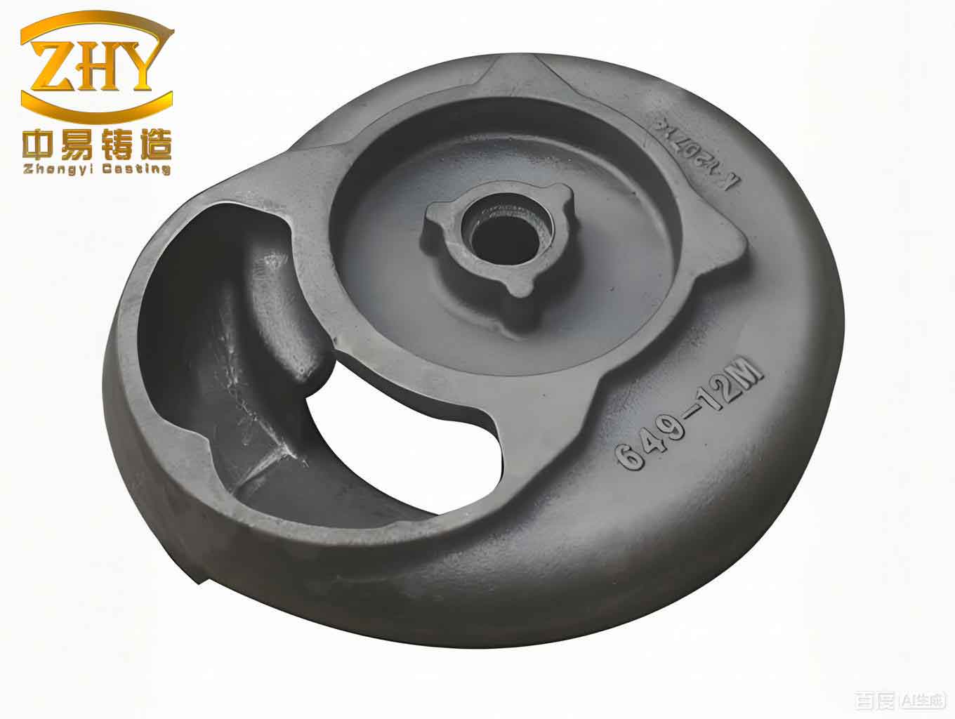
Case Studies in Sand Casting Valve Shells
To illustrate the application of these principles, I present three generalized case studies derived from producing various silicon brass valve shells. These examples highlight how tailored sand casting processes can yield reliable sand casting products, even for complex geometries.
Case 1: Multi-Port Valve Shell
This valve shell features a multi-port design with several flanges and thin walls, requiring careful attention to filling and补缩. The casting dimensions approximately 500 mm in length, with a minimum wall thickness of 10 mm. The key challenge was to prevent cold shuts and shrinkage in the thick flange regions while maintaining leak-proof integrity under high-pressure testing.
Process Design:
- Pattern and Core Making: A horizontal parting plane was used with two dry-sand cores to form internal cavities. The mold was prepared using green sand for the cope and drag.
- Riser Placement: A top riser was placed on the thickest flange (38 mm thick), with dimensions calculated using the modulus method. Side risers were added on adjacent flanges to ensure balanced feeding. For a solid block section, graphite chills were employed instead of risers to avoid reverse shrinkage.
- Gating System: A bottom gating system with a sprue diameter of 30 mm was used, incorporating a ceramic filter (27 holes of 5 mm diameter) to reduce inclusions. The ingates were directed toward the side risers to promote directional solidification.
- Chill Application: Graphite chills of varying thicknesses (12–30 mm) were placed at five locations, including internal cavity areas and external ribs, to enhance cooling.
The process parameters included a pouring temperature of 1000–1020°C, a pattern shrinkage allowance of 1.2%, and a core shrinkage of 0.8%. The resulting casting weight was 46 kg, with a yield of 63%, demonstrating the efficiency of this sand casting approach for producing robust sand casting products.
Case 2: Three-Way Valve Shell
This compact valve shell had two flanges and a thick boss section, with overall dimensions around 450 mm in length. The primary issue was补缩 of the boss without causing defects in the thin walls.
Process Design:
- Core Strategy: A single integrated core was used to support all internal cavities, with careful consideration to prevent core sagging in curved sections.
- Riser Configuration: A small top riser (70 mm diameter) was placed on the boss, complemented by side risers on the flanges. The risers were arranged in a triangular pattern to ensure uniform feeding.
- Gating System: A stepped gating system was employed, where metal was initially poured through the sprue and later through risers to maintain thermal gradient. The cross-sectional area ratio followed the recommended values.
- Chill Usage: Graphite chills were applied at multiple internal and external locations to control solidification rates.
Pouring temperature was maintained at 980–1020°C, with a shrinkage allowance of 1.2%. The casting weighed 36 kg, with a yield of 54.6%, underscoring the adaptability of sand casting processes for diverse sand casting products.
Case 3: Small-Scale Valve Shell
This valve shell had uniformly thin walls (4 mm) with intricate grids and small bosses, posing challenges in complete filling and avoiding oxide inclusions.
Process Design:
- Pattern and Core Details: Two cores were used, with the main core made of resin sand for better stability. A horizontal parting plane facilitated mold assembly.
- Riser and Chill Plan Due to the thin sections, risers were minimized; instead, two feeding gates were designed as small risers on thicker bosses. Graphite chills (30 mm thick) were placed on other bosses to promote rapid solidification.
- Gating System: A runner system led to two feeding pockets, from which metal flowed into the casting through boss gates. A ceramic filter with 23 holes of 4 mm diameter was included to trap oxides.
- Allowances: Extra machining allowances (1.5 mm on grids) were added to account for potential finishing needs.
The pouring temperature was controlled within 980–1000°C, with a pattern shrinkage of 1.2%. The final casting weighed 5 kg, with a yield of 50%, highlighting how sand casting can produce precise, lightweight sand casting products even for demanding applications.
Table 2 summarizes the key process parameters and outcomes for these case studies, emphasizing the consistency achievable in sand casting products through systematic design.
| Case | Casting Weight (kg) | Pouring Temperature (°C) | Riser Type | Chill Usage | Yield (%) | Defects Prevented |
|---|---|---|---|---|---|---|
| Multi-Port | 46 | 1000–1020 | Top and Side | Extensive | 63 | Cold shuts, shrinkage |
| Three-Way | 36 | 980–1020 | Top and Side | Moderate | 54.6 | Porosity, oxides |
| Small-Scale | 5 | 980–1000 | Minimal | Targeted | 50 | Cold shuts, inclusions |
Mathematical Modeling and Optimization
To further enhance the reliability of sand casting products, mathematical models can be employed to simulate solidification and fluid flow. Based on my work, I often use the following equations to optimize工艺 parameters. The solidification time (\(t_f\)) for a sand casting can be estimated using Chvorinov’s rule:
$$t_f = B \cdot \left( \frac{V}{A} \right)^n$$
where \(B\) and \(n\) are constants dependent on the mold material and alloy properties. For silicon brass in green sand molds, \(B \approx 2.0 \, \text{min/cm}^2\) and \(n \approx 2\). This helps in determining the appropriate riser placement to ensure feeding until solidification is complete.
Additionally, the pressure required to avoid mistruns in thin sections can be derived from Bernoulli’s principle applied to gating design:
$$P = \rho g h + \frac{1}{2} \rho v^2$$
where \(\rho\) is the metal density, \(g\) is gravity, \(h\) is the sprue height, and \(v\) is the flow velocity. For ZCuZn16Si4, with \(\rho \approx 8300 \, \text{kg/m}^3\), maintaining a minimum \(P\) ensures complete filling, critical for intricate sand casting products like valve grids.
Optimization of chill placement can be guided by thermal analysis using Fourier’s law. The heat flux (\(q\)) from the casting to the chill is:
$$q = -k \frac{dT}{dx}$$
where \(k\) is the thermal conductivity of the chill material. By simulating temperature gradients, ideal chill positions can be identified to minimize thermal stresses and defects.
Defect Prevention Strategies
Producing high-integrity sand casting products necessitates proactive measures against common defects. For silicon brass valve shells, the primary concerns are cold shuts, shrinkage porosity, and oxide inclusions. My experience suggests the following strategies:
- Cold Shuts: These occur due to premature solidification of metal streams. To prevent them, ensure rapid filling by optimizing gating ratios and using higher pouring temperatures within the range 980–1020°C. The gating system should direct metal to thin walls first, as demonstrated in the case studies.
- Shrinkage Porosity: This results from inadequate feeding during solidification. Implement directional solidification via risers and chills. The riser size should be calculated using modulus methods, and chills should be used for isolated hot spots. Regularly验证 riser efficiency through simulation or experimental trials.
- Oxide Inclusions: Silicon brass has lower oxidation tendency, but inclusions can still form. Use ceramic filters in the runner system and maintain a reducing atmosphere in the furnace. Proper degassing practices, such as using nitrogen purging, can further improve metal cleanliness for sand casting products.
Table 3 outlines the relationship between process variables and defect occurrence, serving as a quick reference for foundry engineers.
| Process Variable | Optimal Range for ZCuZn16Si4 | Defect Mitigated | Effect |
|---|---|---|---|
| Pouring Temperature | 980–1020°C | Cold Shuts | Enhances fluidity |
| Riser Modulus | 1.2–1.5 × Casting Modulus | Shrinkage Porosity | Ensures adequate feeding |
| Chill Thickness | 10–30 mm | Microporosity | Accelerates cooling |
| Gating Ratio | Fsprue:Ffilter:Frunner:Fingate = 1.5:1:2.5:>5 | Oxide Inclusions | Reduces turbulence |
| Mold Material | Green sand with 5–7% clay | Surface Defects | Provides good refractoriness |
Economic and Quality Considerations
The sand casting process for marine valve shells must balance cost-effectiveness with stringent quality requirements. As I have observed, optimizing the yield—defined as the ratio of casting weight to total poured weight—is crucial for reducing material waste and energy consumption. For sand casting products like these valves, yields typically range from 50% to 65%, depending on complexity. Higher yields can be achieved by integrating simulation tools to minimize riser volumes and improve gating design.
Quality assurance involves non-destructive testing methods, such as pressure testing at 4.5–4.8 MPa for 5 minutes, as specified for marine applications. Additionally, microstructure analysis using metallography can reveal any hidden defects. The consistent performance of sand casting products under such tests validates the工艺 efficacy. Furthermore, adopting statistical process control (SPC) charts to monitor variables like pouring temperature and mold hardness can enhance reproducibility across production batches.
Conclusion
In summary, the sand casting of silicon brass ZCuZn16Si4 marine valve shells is a nuanced process that demands a deep understanding of material behavior and工艺 dynamics. Through the principles and case studies discussed, I have demonstrated how strategic riser placement, optimized gating systems, and judicious chill usage can prevent defects and produce reliable sand casting products. The mathematical models and tables provided offer practical tools for foundry professionals to refine their processes. As the demand for durable marine components grows, mastering these sand casting techniques will remain essential for delivering high-performance valves that meet rigorous standards. By continuously integrating empirical insights with computational aids, we can advance the art and science of sand casting, ensuring that every sand casting product contributes to safer and more efficient marine operations.
Reflecting on my journey in this field, I am convinced that the versatility and reliability of sand casting make it indispensable for manufacturing complex parts like valve shells. Whether for large multi-port designs or small intricate ones, the adaptability of this process underscores its value in producing sand casting products that withstand the harsh marine environment. I encourage further research into alloy modifications and process innovations to push the boundaries of what sand casting can achieve.