
In the rapidly evolving automotive industry, the demand for high-performance, reliable, and cost-effective components is paramount. Brake calipers, as critical safety components, require exceptional mechanical properties, internal soundness, and dimensional accuracy. The shift towards lighter and more efficient vehicles further necessitates the use of advanced materials and manufacturing processes. Spheroidal graphite cast iron, commonly known as ductile iron, stands out for this application due to its excellent combination of strength, ductility, and castability. In my extensive experience developing casting processes, a primary challenge is maximizing production efficiency and yield without compromising quality. This article details an innovative approach to the casting process for an automotive brake caliper made from spheroidal graphite cast iron, focusing on a strategic layout change that significantly enhances yield and productivity.
The component in question is a brake caliper with a nominal weight of 3.02 kg and overall dimensions of 185 mm x 74 mm x 163 mm. The material specification is QT450-10, a grade of spheroidal graphite cast iron. The technical requirements for this part are stringent, governing its chemistry, microstructure, mechanical performance, and integrity.
| Element | Required Range (wt.%) |
|---|---|
| C | 3.3 – 3.9 |
| Si | 2.2 – 3.2 |
| Mn | 0.1 – 0.4 |
| P | ≤ 0.08 |
| S | ≤ 0.02 |
| Cu | ≤ 0.2 |
The metallographic structure must exhibit a nodularity greater than 80%, with graphite size between grade 5 and 8, and a matrix primarily composed of ferrite and pearlite. The mechanical properties must meet or exceed: Tensile Strength (Rm) ≥ 450 MPa, Yield Strength (Rp0.2) ≥ 280 MPa, Elongation (A) ≥ 10%, and a Brinell Hardness between 143 and 217 HBW. Internally, the casting must be free from shrinkage porosity, cavities, cracks, and gas-related defects, while the surface must be clean of any sand inclusions, slag holes, or other imperfections that could affect assembly or appearance.
The production was slated for a DISA 230B vertically parted, flaskless, shoot-squeeze molding machine. The standard plate dimensions for this machine are 650 mm x 535 mm. The conventional and most intuitive method for casting such a component is to orient it with the critical cylinder bore section vertical. Preliminary layout attempts using this orientation revealed a significant limitation. While trying to arrange six castings per mold to maximize output, it became evident that there was insufficient space on the sides to accommodate the necessary gating and feeding systems, and the sand margins were inadequate. This forced a compromise, reducing the count to only four castings per mold in the conventional layout. The process yield for this configuration was calculated and found to be sub-optimal. The yield, or casting yield, is a crucial metric defined as the ratio of the total weight of sound castings to the total weight of metal poured. For high-volume production, even a single percentage point improvement is economically significant.
This limitation prompted a fundamental re-evaluation of the part orientation. I proposed rotating the casting 90 degrees, placing the cylinder bore horizontally. This simple yet transformative change dramatically altered the spatial geometry on the pattern plate. The horizontal orientation presented a narrower profile, allowing three castings to be placed side-by-side across the width of the plate. Furthermore, this arrangement left enough vertical space to stack two rows. Consequently, a six-casting layout became feasible. Strategic placement was key: four castings were oriented in one direction, and the remaining two were mirrored. This clever arrangement created optimal cavities for positioning risers and routing the gating system efficiently within the constrained space. The improvement in process yield was substantial, increasing from approximately 52% in the conventional 4-up layout to 61.6% in the new 6-up layout—a relative improvement of nearly 19%. This directly translates to less molten metal required per good casting, reducing energy consumption and production cost.
With the layout finalized, the detailed design of the feeding system commenced. The goal is to ensure directional solidification towards the riser, preventing internal shrinkage. The modulus method is a reliable engineering approach for this. The modulus (M) is defined as the volume (V) of a section divided by its cooling surface area (S).
$$M = \frac{V}{S}$$
First, I calculated the modulus of the main casting body and identified the thermal center, or hot spot, at the junction of thicker sections. The modulus of the hot spot, \( M_{hotspot} \), was determined to be approximately 5.9 mm. To ensure effective feeding, the riser must solidify after the casting. Therefore, the riser modulus \( M_{riser} \) should satisfy:
$$M_{riser} \geq 1.2 \times M_{hotspot}$$
Applying a factor of 1.3 for safety, the required riser modulus was 7.67 mm. Given spatial constraints, a spherical riser with a diameter of 58 mm was selected. To further enhance its feeding capacity, a 15 mm thick padding was added at its connection to the casting. The final riser modulus was verified to be 8.6 mm, satisfactorily exceeding the requirement. Each casting was fed by a single riser placed directly above it, which is ideal for feeding spheroidal graphite cast iron as it promotes atmospheric pressure-assisted feeding. These risers were designed as “hot risers,” meaning they receive direct metal flow from the gating system to keep them molten longer.
The gating system design required special attention due to the top-located hot risers. A purely top-gated system would cause severe turbulence and erosion of the mold cavity. To achieve calm filling, I implemented a combined gating strategy. The system was designed as semi-pressurized, with the relationship:
$$ \Sigma A_{sprue} : \Sigma A_{runner} : \Sigma A_{ingate} = 1 : 0.7 : 1.2 $$
The total cross-sectional areas were 500 mm², 350 mm², and 600 mm² for the sprue, runner, and ingates, respectively. To save space, one sprue feeds four castings (#1-#4), and a separate sprue feeds the remaining two (#5-#6). The key innovation was introducing a thin (1 mm) horizontal gate at the very bottom of the mold cavity for each casting. This ensures that the initial metal enters quietly at the base. Simultaneously, metal is also introduced directly into the riser cavity from the top. The result is a balanced fill: the bottom gates establish a calm metal rise, while the top-feeding ensures the risers are hot. This design effectively minimizes oxidation, slag entrapment, and mold erosion. Pouring parameters were set with a start temperature of 1420°C, an end temperature of 1370°C, and a total pour time for the mold of 8 seconds.
Prior to committing to tooling, numerical simulation using MAGMAsoft was employed to validate the design. The filling simulation confirmed a tranquil fill pattern with minimal air entrainment. The temperature gradient during filling was smooth, indicating no premature chilling in critical areas. The solidification simulation was even more critical. The results showed a clear progression of the solidification front from the extremities of the casting back towards the risers. Most importantly, the simulation did not reveal any isolated liquid pools, or “hot spots,” within the main body of the castings, which are the precursors to shrinkage porosity. The risers themselves remained liquid until the very end, confirming their effectiveness as feed reservoirs. This virtual validation provided high confidence in the soundness of the proposed process for the spheroidal graphite cast iron component.
Successful casting is not only about design but also about consistent and controlled production. The green sand properties are fundamental to achieving good surface finish and dimensional accuracy. The sand is a mixture of reclaimed sand, new silica sand, bentonite (bond), and coal dust (for lustrous carbon). The mixing sequence and time are controlled precisely.
| Parameter | Control Range |
|---|---|
| Moisture Content | 3.2 – 3.4 % |
| Compactability | 38 – 42 % |
| Permeability | 100 – 120 |
| Green Compression Strength | 0.17 – 0.21 MPa |
| Active Bentonite | 7 – 9 % |
| Loss on Ignition | 3 – 6 % |
The melting process for spheroidal graphite cast iron is a carefully orchestrated sequence. The charge consists of 50% returns, 20% pig iron (Q10 grade), and 30% steel scrap. Carbon additive is added with the steel scrap to maximize its dissolution and recovery. The molten base iron is superheated to 1535-1555°C and held for 3-5 minutes to ensure homogeneity and thorough dissolution of carbon. The target chemistry for the base iron before treatment is critical for successful nodularization.
| Element | Target Range (wt.%) |
|---|---|
| C | 3.80 – 3.85 |
| Si | 2.00 – 2.10 |
| Mn | 0.25 – 0.30 |
| S | ≤ 0.025 |
| P | ≤ 0.06 |
A core wire injection method was chosen for nodularization. This method offers excellent magnesium recovery, minimal fume generation, and precise control. The cored wire contains 29.5-32.5% Mg and 2.0-2.5% Rare Earth elements. The treatment parameters are tightly controlled: a specific wire length and speed, a treatment temperature of 1430-1450°C, and a reaction time of 40-60 seconds under a covered ladle. The residual magnesium content is targeted between 0.040% and 0.050%. Effective inoculation is paramount for achieving the required high nodule count and preventing chilling in spheroidal graphite cast iron. A triple inoculation practice was implemented:
- Pre-inoculation: 0.2% Si-Ba inoculant (2.6-4.5 mm) added to the transfer ladle during tapping.
- Post-inoculation: 0.3% Si-Ba inoculant (0.6-2.5 mm) added during transfer from the treatment ladle to the pouring furnace.
- Late Inoculation: A stream inoculation using fine (0.2-0.5 mm) Si-Ba inoculant at a rate of 3 g/s during pouring.
This robust inoculation strategy ensures a uniform, fine distribution of graphite nodules throughout the casting section.
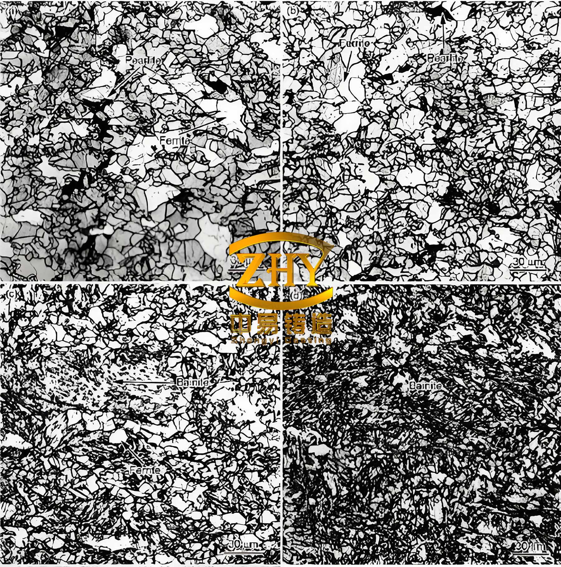
The castings produced via this optimized process were subjected to comprehensive testing. Chemical analysis confirmed the final composition was well within specification, with residual Mg around 0.044-0.050%. Metallographic examination of samples taken from a critical 20 mm thick section revealed excellent microstructure. The nodularity consistently exceeded 90%, with graphite size predominantly at grade 6-7. The matrix was a favorable mix of approximately 75% ferrite and 25% pearlite, with no presence of free carbides. This microstructure is ideal for achieving the required ductility and strength in spheroidal graphite cast iron.
Mechanical tests were performed on separately cast test bars (for reference) and on samples machined from the caliper body itself (to verify本体 properties). The results surpassed the QT450-10 specifications.
| Sample | Tensile Strength (MPa) | Yield Strength (MPa) | Elongation (%) | Hardness (HBW) |
|---|---|---|---|---|
| 1 | 476 | 336 | 15.6 | 180 |
| 2 | 479 | 331 | 13.3 | 178 |
| 3 | 485 | 327 | 13.3 | 168 |
| 4 | 472 | 331 | 18.6 | 164 |
| 5 | 462 | 321 | 20.0 | 188 |
| 6 | 479 | 334 | 17.0 | 172 |
Non-destructive testing via X-ray radiography and destructive sectioning with dye penetrant inspection were conducted on multiple castings. No indications of shrinkage porosity, cavities, or cracks were found in the critical sections, confirming the effectiveness of the risering and gating design. The internal soundness of the spheroidal graphite cast iron castings was fully validated.
In mass production, the process demonstrated remarkable stability. The rejection rate for individual castings in the 6-cavity mold ranged between 1.5% and 2.3%, yielding a total process scrap rate of under 1.9%. This is an excellent rate for a complex, safety-critical casting. The consistent quality, coupled with the 19% improvement in yield from the layout optimization, delivers significant economic and operational benefits.
This case study underscores the importance of innovative thinking in foundry process design. By challenging the conventional vertical orientation for the brake caliper cylinder and adopting a horizontal placement, we unlocked the potential to increase the mold cavity count by 50%. This was achieved not in isolation, but through an integrated redesign of the feeding and gating system, supported by numerical simulation and grounded in robust metallurgical controls for spheroidal graphite cast iron. The result is a highly efficient, reliable, and quality-conscious manufacturing process for a critical automotive component. The principles demonstrated here—strategic orientation for yield improvement, balanced gating for sound filling, modulus-based riser design, and rigorous process control—are broadly applicable to enhancing the production of other complex castings in spheroidal graphite cast iron and similar alloys.