
The performance and service life of work rolls are critical determinants of efficiency and cost in modern hot strip rolling mills. As consumable components directly interacting with the hot workpiece under severe thermo-mechanical conditions, rolls account for a significant portion (5–15%) of production costs. Their key properties—wear resistance, strength, hot hardness, and toughness—directly influence mill productivity and product yield. Consequently, roll quality fundamentally governs overall rolling economics and equipment availability. The evolution of roll materials has progressed from conventional nodular and alloy indefinite chill irons to advanced alloys exhibiting superior performance, including acicular matrix ductile irons, high-alloy indefinite chill irons, high-chromium irons, carbide-reinforced grades, and semi-high-speed or high-speed steels. Parallel advancements in manufacturing processes have moved beyond static casting to sophisticated methods such as Centrifugal Casting (CF), Continuous Pouring Process for Cladding (CPC), Electroslag Remelting (ESR), Hot Isostatic Pressing (HIP), and Spray Forming (OSPREY). Among these, centrifugal casting stands out for the production of composite rolls due to its relative equipment simplicity, high production efficiency, favorable cost structure, and ability to yield dense, defect-reduced microstructures, making it the preferred industrial process.
Centrifugal casting involves pouring molten metal into a rapidly rotating mold. The imposed centrifugal force drives the metal against the mold wall, facilitating mold filling and promoting directional solidification from the outer surface inward. This process is categorized by the axis of rotation: horizontal, vertical, or inclined, with horizontal centrifugal casting being the standard for manufacturing long, cylindrical components like rolls. The significant technical advantages of this method stem from the high centrifugal forces, which enhance metal density, minimize gaseous porosity, shrinkages, and non-metallic inclusions, and promote a refined, often columnar, grain structure.
High-nickel-chromium indefinite chill spheroidal graphite cast iron is a premier material for the working layer of composite rolls in finishing stands of hot strip mills. This alloy, characterized by high contents of nickel, chromium, and molybdenum, offers an exceptional combination of high hardness, outstanding wear resistance, and excellent thermal fatigue (heat checking) resistance. The production of these composite rolls typically employs a two-stage centrifugal casting process: first, the high-alloy working layer is centrifugally cast in a horizontal machine; after its solidification, the mold containing this shell is assembled vertically with pre-heated sand molds for the upper and lower necks; finally, the core, made of a tough and strong ferritic or pearlitic spheroidal graphite cast iron, is gravity poured. This sequence aims to achieve a sound metallurgical bond between the hard working layer and the ductile core, delivering the desired integrated performance.
While established, the centrifugal composite casting process is complex, with numerous interacting parameters. Inadequate control can lead to defects such as excessive residual stress, poor bonding between layers, chemical segregation, and porosity. Traditional trial-and-error optimization through physical experiments is costly, time-consuming, and inefficient. The advent of computational numerical simulation has revolutionized foundry practice, enabling virtual visualization of the entire casting process—including filling dynamics, temperature fields, stress development, and even grain structure evolution—thereby allowing for rapid, cost-effective process design and optimization.
In this study, we employ finite element simulation software to design and analyze the centrifugal casting process for the working layer of a high-nickel-chromium indefinite chill spheroidal graphite cast iron composite roll. We designed the following computational approach, analyzed the filling and solidification behavior in detail, and validated the simulation predictions with actual production trials and metallographic examination.
| Element | C | Si | Mn | Cr | Ni | Mo | S | P |
|---|---|---|---|---|---|---|---|---|
| wt.% | 3.43 | 1.30 | 0.85 | 1.80 | 4.33 | 0.35 | 0.015 | 0.06 |
The target roll working layer had finished dimensions of 680 mm in length, 475 mm outer diameter, and a thickness of 90 mm. The three-dimensional model of the mold assembly, including the steel mold (material: hot-work tool steel 40CrMoV5) and the cavity, was created and discretized into a finite element mesh with approximately 430,000 elements. The thermo-physical properties of the spheroidal graphite cast iron alloy were calculated by the software based on the composition in Table 1. Key thermal parameters were identified: the liquidus temperature was 1239°C, and the solidus temperature was 1051°C. The following assumptions and boundary conditions were applied for the simulation:
- The molten spheroidal graphite cast iron was treated as a single-phase, incompressible fluid.
- The steel mold was assumed to undergo only elastic deformation (no plasticity).
- The initial mold preheat temperature was set at 180°C.
- The pouring temperature of the iron was 1340°C, with a constant pouring rate of 25 kg/s.
- The mold rotated steadily around its horizontal axis (Z-axis) at 800 rpm.
- The heat transfer coefficient (HTC) between the mold and the surrounding air was 25 W/(m²·K).
- The interfacial HTC between the solidifying metal and the mold wall was set to 3000 W/(m²·K).
It is important to note that standard simulation packages often have built-in modules optimized for vertical centrifugal casting. For horizontal processes, a critical modification is required: the filling stage must be conceptually divided into two distinct phases to accurately capture the physics.
Filling Behavior and Flow Field Analysis
The initial stage, termed Gravity-Driven Flow, occurs from the moment the stream of molten spheroidal graphite cast iron leaves the pouring ladle until it first impacts the inner wall of the rotating mold. During this brief period, the metal flow is primarily governed by gravity and initial momentum, following a parabolic trajectory. The centrifugal force has negligible effect as the metal is not yet coupled to the mold’s rotation.
The second stage, Centrifugal-Driven Flow and Spread, begins upon impact. The molten metal instantly couples to the rotating mold wall due to friction. From this point onward, the metal experiences a complex force field comprising centrifugal force $$(F_c = m \omega^2 r)$$, gravity, and wall friction. The resultant force causes the metal to form a thin, coherent layer that travels circumferentially with the mold. Simultaneously, this layer spreads axially along the mold wall. Our simulation results indicate that the flow front advances faster towards the end of the mold closer to the pour point, subsequently spreading towards the opposite end. The sequential snapshots of the filling process, characterized by the fill percentage (fp), clearly demonstrate this mechanism.
| Simulation Time (s) | Fill Percentage (fp%) | Flow Characteristics |
|---|---|---|
| 1.1 | 4.3 | Initial impact and circumferential film formation. |
| 8.0 | 31.1 | Axial spreading initiated, layer thickness non-uniform. |
| 13.3 | 50.0 | Mold wall fully wetted, thickness gradient evident. |
| 16.7 | 62.2 | Continued filling gradually homogenizes layer thickness. |
| 23.1 | 85.2 | Layer near uniform, final stages of filling. |
| 27.1 | 99.3 | Filling essentially complete, shape regular and uniform. |
The total filling time was simulated to be approximately 27.3 seconds. A key observation is that the centrifugal force dominates over gravity throughout the filling stage after initial impact, ensuring the metal remains firmly pressed against the mold wall, leading to excellent replication of the mold surface and dense packing.
Solidification Behavior and Temperature Field Analysis
The temperature field evolution during filling reveals significant initial chilling. As the first metal contacts the relatively cool (180°C) mold, a steep thermal gradient is established, causing the outer metal skin to drop below the solidus temperature rapidly, forming a thin solidified shell. This is evident in early-stage temperature contours. As more hot metal is added, the mold temperature rises, reducing the chilling severity for subsequent layers. By the end of the pour, the temperature distribution within the molten spheroidal graphite cast iron layer becomes more uniform.
The post-filling solidification analysis shows a predictable and desirable directional cooling pattern. Heat is extracted through two primary paths: radially outward through the metal mold and axially through the mold end walls. Consequently, solidification progresses simultaneously from the two cylindrical surfaces and the two end faces inward. The solid fraction development over time illustrates this clearly.
The radial thermal gradient (outer surface cooler than inner surface) is steeper than the axial gradient due to the higher efficiency of heat extraction through the massive steel mold compared to the sand end closures. This strong radial directional solidification is the primary driver for the formation of columnar dendrites growing perpendicularly from the mold wall towards the bore of the working layer. The solidification sequence can be summarized by the progression of the solidus isotherm, confirming that the last point to solidify is located towards the inner diameter and mid-length of the cylinder, which is a typical and acceptable result for this geometry.
Mechanism of Microstructural Formation
The solidification microstructure of the high-nickel-chromium indefinite chill spheroidal graphite cast iron is a direct consequence of the thermal history imposed by the centrifugal process. The combination of a high alloy content (Ni, Cr, Mo) and the intense chilling from the mold wall creates significant constitutional undercooling at the solidification front. This condition is highly favorable for dendritic growth.
Upon contact with the mold, nucleation occurs profusely at the chill surface. However, the steep thermal gradient preferentially selects grains with orientations most favorable for heat extraction (typically those with a primary arm aligned with the gradient) for continued growth. These grains develop into columnar dendrites, with primary trunks growing radially inward and secondary arms branching out. The high nickel content, a strong graphitizer, and effective inoculation ensure that the graphite precipitates in a well-formed spheroidal morphology throughout the matrix, even within this dendritic framework. The final as-cast matrix of this spheroidal graphite cast iron consists of a mixture of bainite, martensite, and retained austenite, providing the required hardness and strength.
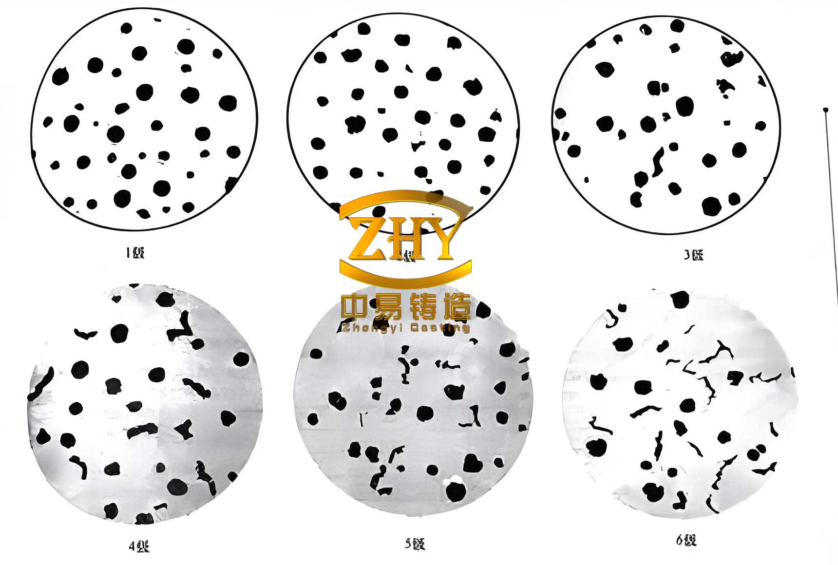
The centrifugal force plays a crucial indirect role in microstructure formation. By ensuring excellent contact with the mold and eliminating air gaps, it maximizes the heat transfer rate, thereby stabilizing the planar and later columnar growth fronts and discouraging equiaxed grain formation in the outer zones. It also helps in floating lighter impurities (like certain slag particles) towards the inner free surface, purifying the working layer material.
Industrial Trial and Validation
Guided by the simulation insights, a production trial was conducted for a Ø475 mm × 680 mm composite roll. The working layer of spheroidal graphite cast iron was poured at 1340°C into a horizontally spinning mold (preheated to ~180°C) rotating at 800 rpm. The rotational speed was calculated using the empirical formula:
$$ n = \beta \frac{55200}{\sqrt{\rho R}} $$
where \( n \) is the rotational speed (rpm), \( \beta \) is an empirical factor (1.2–1.5), \( \rho \) is the alloy density, and \( R \) is the inner radius of the mold (mm). After pouring, exothermic insulating compounds were added to the bore to prevent oxidation and control the cooling rate. Following the solidification of the working layer, the assembly was positioned vertically, and the ductile iron core was gravity cast.
The resulting roll was inspected after rough machining. Ultrasonic testing confirmed an excellent metallurgical bond between the high-alloy spheroidal graphite cast iron working layer and the core. No significant shrinkage cavities, porosity, or slag inclusions were detected on the roll neck surfaces. The hardness of the working layer measured 76 HSD (approx. 58 HRC), meeting the technical specification. Metallographic samples extracted from the working layer confirmed the predicted microstructure: a dendritic matrix with well-dispersed, finely sized spheroidal graphite (nodularity >95%, size class 8) and a hard matrix phase mixture.
| Property / Feature | Result | Status |
|---|---|---|
| Working Layer Hardness | 76 HSD | Meets Specification |
| Bond Integrity (Ultrasonic Test) | Sound, no discontinuities | Acceptable |
| Surface Quality (Neck) | Free of major pores/slag | Acceptable |
| Graphite Nodularity | >95% (Grade 1) | Excellent |
| Matrix Structure | Dendritic Bainite/Martensite/Austenite | As Expected |
Conclusions
Our study demonstrates the effective application of finite element numerical simulation in designing and optimizing the horizontal centrifugal casting process for high-performance roll working layers made of high-nickel-chromium indefinite chill spheroidal graphite cast iron. The simulation provided a clear visualization of the two-stage filling mechanism and the directional solidification pattern. The predicted flow behavior, thermal history, and resultant microstructural characteristics aligned closely with the outcomes of the industrial production trial. The successful manufacture of rolls meeting all quality and performance benchmarks validates the accuracy of the simulation model and its parameters. This approach provides a powerful, cost-effective tool for refining process parameters, minimizing defects, and ensuring consistent production of high-quality centrifugally cast spheroidal graphite cast iron components for demanding rolling mill applications.