
The production of heavy-section spheroidal graphite cast iron components presents significant metallurgical challenges. Due to their large modulus, low undercooling, limited number of graphite nucleation sites, and the influence of elements promoting austenite dendrite formation, the solidification process is prolonged. This leads to the development of extensive, branched austenite dendrites which adversely affect the formation and distribution of eutectic graphite. Common defects include chunky graphite, exploded graphite, deformed graphite, as well as fading of spheroidization and/or inoculation. These issues severely compromise the spheroidization rate, which in turn deteriorates the mechanical properties of the final casting. This article details a systematic investigation aimed at understanding and controlling the spheroidization rate in heavy-section spheroidal graphite cast iron, utilizing a large-scale test block to simulate real-world production conditions.
1. Experimental Design: Simulation via Large Test Block
To accurately replicate the solidification characteristics of heavy-section castings, a large test block with dimensions of 400 mm × 400 mm × 400 mm was designed. The solidification time for such a geometry is a critical parameter and can be estimated using established empirical rules or solidification simulation software. The solidification time \( t \) is often related to the casting’s modulus \( M \) (volume-to-surface-area ratio) and the pouring temperature. For a cube of side length \( L \), the modulus is \( M = \frac{V}{A} = \frac{L^3}{6L^2} = \frac{L}{6} \). For our block, \( L = 0.4 \, \text{m} \), so \( M \approx 0.0667 \, \text{m} \). Using Chvorinov’s rule, \( t = B \cdot M^n \), where \( B \) and \( n \) are constants dependent on the mold material and metal properties. For a resin sand mold and a pouring temperature of 1340°C, the calculated solidification time was approximately 4 hours, effectively simulating the slow cooling of a heavy-section component.
1.1 Gating System and Molding
The gating system was designed to ensure smooth filling and provide limited liquid feeding during the long solidification period. A vertical sprue was used to facilitate feeding, and the metal entered the cavity through a narrow, vertical slot gate on the side of the block to maintain a tranquil melt front. The casting layout is schematically represented in the figure. The molding process strictly avoided the use of chills or high-chromite sands to prevent artificially accelerating cooling. Instead, standard furan resin sand was used to create the mold from a 1% shrunken expandable polystyrene (EPS) pattern, coated with a high-refractoriness zircon-based paint and dried, thereby closely mimicking typical production conditions for large castings.
1.2 Sampling Methodology
To assess property variation from the surface to the center (the most critical region for defect formation), a detailed sampling plan was implemented. As shown in the schematic, three cylindrical bars of Ø30 mm × 400 mm were extracted from the test block at distances of 100 mm, 200 mm, and 350 mm from one side. Each bar was then sectioned into two halves, yielding a total of six Ø30 mm × 200 mm samples. From these, standard Ø14 mm tensile specimens were machined according to GB/T 1348-2009 (equivalent to ISO 1083) for tensile testing and metallographic examination. This provided a comprehensive map of mechanical properties and microstructure from near-surface to the thermal center.
1.3 Charge Composition and Melting Base
To mitigate the genetic effects of coarse graphite from pig iron and to reduce cost, the primary charge materials consisted of 40-60% selected steel scrap (clean punching scrap to minimize oxides) and 40-60% known-composition returns (gates and risers). High-quality, high-temperature graphitizing recarburizer was added during melting to achieve the target carbon content, ensuring good metallurgical quality of the base iron. This approach minimizes the influence of trace elements that can distort graphite morphology.
2. Chemical Composition and Metallurgical Considerations
The selection of chemical composition is paramount for heavy-section spheroidal graphite cast iron. The primary goals are to prevent graphite flotation, suppress chunky graphite formation, and ensure adequate mechanical properties. The target composition ranges were established based on the block’s modulus and desired microstructure.
| Element | Target Range | Rationale |
|---|---|---|
| Carbon (C) | 3.45 – 3.60 | Balances fluidity, shrinkage, and graphite amount. Higher carbon increases graphitization potential but risks flotation. |
| Silicon (Si) | 2.10 – 2.25 | Promotes ferrite, increases fluidity and graphitization. Controlled to prevent excessive ferrite and low-temperature embrittlement. |
| Carbon Equivalent (CE) | 4.15 – 4.25 | CE = %C + 1/3(%Si+%P). Critical for controlling eutectic solidification mode and undercooling. |
| Manganese (Mn) | 0.30 – 0.40 | Provides solid solution strengthening and promotes pearlite. Segregation to cell boundaries must be considered. |
| Phosphorus (P) | < 0.07 | Harmful element forming brittle phosphide eutectic at boundaries. Minimized. |
| Sulfur (S) | < 0.02 | Harmful, consumes Mg to form MgS. Low level is essential for efficient and stable spheroidization. |
| Magnesium (Mg)res | 0.035 – 0.045 | Essential for graphite spheroidization. This level is considered adequate under low-sulfur conditions even for heavy sections. |
| Antimony (Sb) | 0.003 – 0.005 | Added to counteract the negative effects of rare earths (RE) and slow cooling. Sb hinders carbon diffusion, stabilizing the austenite shell around graphite. |
The carbon equivalent (CE) is a key parameter. For the initial trial, a relatively low CE was chosen to avoid graphite flotation, calculated as:
$$ CE = C\% + \frac{1}{3}(Si\% + P\%) $$
with target values between 4.15% and 4.25%.
3. Spheroidization and Inoculation Treatment Strategy
The treatment process is critical for generating sufficient nucleation sites and maintaining spheroidization throughout the long solidification. The strategy involved using a low-rare-earth spheroidizer followed by a robust, multi-stage inoculation process.
| Material | Composition (wt.%) | Addition Rate (wt.%) | Purpose |
|---|---|---|---|
| Spheroidizer | Mg: 5.5-6.0, RE: 0.8-1.0 | 1.1 – 1.3 | Provides Mg for spheroidization. Low RE minimizes promotion of chunky graphite. |
| Primary Inoculant | Ba: 4-6 | 0.4 – 0.6 | Enhances nucleation potential, delays inoculation fade. Added during transfer (post-inoculation). |
| Stream Inoculant | Contains Bi, Ba | 0.1 – 0.25 | Provides fresh, active nuclei immediately before solidification begins in the mold. |
The base iron was superheated to approximately 1500°C to ensure dissolution of nuclei and then cooled to the treatment temperature. The spheroidizer was placed in the bottom of a preheated treatment ladle and covered with a small amount (0.2%) of inoculant. The iron was poured onto it using the sandwich (or pour-over) method. After spheroidization and slag removal, the primary inoculant was added during transfer to the pouring ladle. Finally, stream inoculation was applied during casting. The pouring temperature was set at 1340 ±10°C.
4. Initial Trial Results and Analysis
The mechanical properties and microstructure of the first trial block were evaluated. The results revealed significant problems, particularly in the thermal center of the casting.
| Sample Location | Tensile Strength, Rm (MPa) | Yield Strength, Rp0.2 (MPa) | Elongation, A (%) | Hardness (HBW) |
|---|---|---|---|---|
| Upper / 100mm | 363 | 274 | 7.9 | 158 |
| Upper / 200mm | 357 | 272 | 6.3 | 161 |
| Upper / 350mm (Near Center) | 354 | 277 | 6.6 | 158 |
| Lower / 100mm | 359 | 261 | 7.7 | 157 |
| Lower / 200mm | 360 | 263 | 8.3 | 157 |
| Lower / 350mm (Near Center) | 354 | 263 | 7.5 | 158 |
| Sample Location | Spheroidization Rate (Surface-Near) | Spheroidization Rate (Center-Near) | Graphite Form | Graphite Size | Pearlite Content (%) |
|---|---|---|---|---|---|
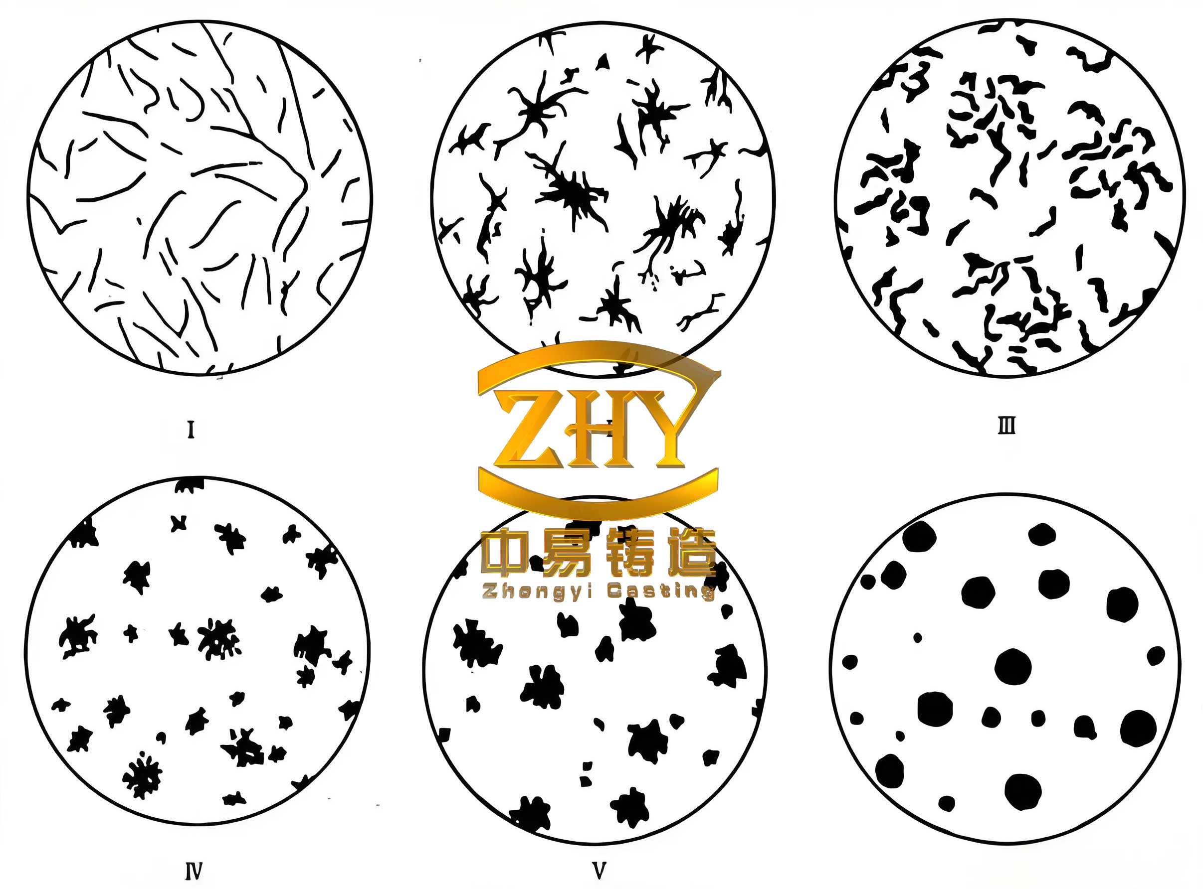
| Various | Grade 2-3 | Grade 5 | Chunky (碎块状) | Grade 5-6 | 5-10 |
The data shows a stark difference between the surface and center regions. While the surface exhibited acceptable spheroidization (Grade 2-3), the center degraded severely to Grade 5, characterized by chunky graphite. This led to unsatisfactory mechanical properties, particularly low elongation, which is highly sensitive to graphite morphology. Chemical analysis of drillings from the surface and center confirmed that macroscopic fading of magnesium was not significant (Mg~0.038-0.039% in both), supporting the theory that in the reducing atmosphere of the mold, Mg loss is minimal. This challenges the conventional wisdom that very high residual Mg is always necessary for heavy-section spheroidal graphite cast iron.
5. Root Cause Analysis: Formation of Chunky Graphite
The prevalence of chunky graphite in the thermal center is attributed to a combination of factors inherent to slow solidification. The primary causes are:
- Low Undercooling and Long Solidification Time: The central region experiences minimal thermal gradient and undercooling (\( \Delta T \)). This disrupts the divorced eutectic growth mode, favoring a cooperative growth where the austenite shell surrounding the graphite becomes unstable. The relationship between growth velocity \( v \) and undercooling is often expressed as \( v = \mu (\Delta T)^n \), where \( \mu \) is a kinetic coefficient and \( n \) is an exponent. Low \( \Delta T \) leads to very slow growth, allowing for graphite degeneration.
- Insufficient Graphite Nucleation Sites: Despite inoculation, the potency and number of nuclei may fade over the extended liquid holding time before the center solidifies. The effective nucleation density \( N \) can be modeled as a function of time \( t \) and temperature \( T \): \( N(t, T) = N_0 \cdot e^{-kt} \cdot f(T) \), where \( N_0 \) is the initial nuclei count and \( k \) is a fading constant.
- Microsegregation of Trace Elements: Elements like Sb and Rare Earths (RE) have time to segregate at the solid-liquid interface during slow cooling. This local enrichment can destabilize the austenite shell, providing pathways for graphite to grow in an irregular, compacted manner, leading to the chunky morphology.
- High Austenite Dendrite Density: The prolonged dendritic growth creates a dense network that confines the remaining liquid. Graphite nodules forming in these confined, interconnected pools are forced to grow into the available space, resulting in a compacted, interconnected structure rather than discrete spheroids.
6. Optimization Measures and Final Results
Based on the analysis, the process was optimized targeting increased graphitization potential, enhanced nucleation, and slightly accelerated solidification.
| Parameter | Initial Trial | Optimized Trial | Reason for Change |
|---|---|---|---|
| Carbon Equivalent (CE) | 4.15 – 4.25% | 4.35 – 4.45% | Increase graphitizing potential, provide more carbon for nucleation and growth, reducing undercooling. Risk of exploded graphite is managed by other factors. |
| Carbon (C) | 3.45-3.60% | 3.65-3.75% | Directly increases CE and graphitization driving force. |
| Pouring Temperature | 1340 ±10°C | 1320 ±10°C | Reduces total solidification time, slightly increases cooling rate/undercooling in the center. |
| Inoculation Strategy | Transfer + Stream | Three-Stage: 1. Covering inoculant during spheroidization (0.2%). 2. Post-spheroidization inoculant (0.4-0.6%). 3. Stream inoculation (0.1-0.25%). | Maximizes nucleation potential throughout the process. Covering inoculant protects Mg and provides early nuclei. Total inoculation increased to 0.7-1.05%. |
| Spheroidization Temperature | ~1500°C | ~1450°C | Lower temperature reduces Mg vaporization loss and turbulence, leading to cleaner iron and more stable treatment. |
The optimized process yielded a dramatic improvement in both the microstructure and mechanical properties of the heavy-section spheroidal graphite cast iron test block.
| Sample Location | Tensile Strength, Rm (MPa) | Yield Strength, Rp0.2 (MPa) | Elongation, A (%) | Hardness (HBW) |
|---|---|---|---|---|
| Upper / 100mm | 390 | 251 | 17.0 | 148 |
| Upper / 200mm | 394 | 252 | 23.5 | 144 |
| Upper / 350mm (Near Center) | 390 | 254 | 18.5 | 145 |
| Lower / 100mm | 385 | 255 | 17.5 | 146 |
| Lower / 200mm | 394 | 255 | 18.5 | 144 |
| Lower / 350mm (Near Center) | 384 | 264 | 20.5 | 148 |
| Sample Location | Spheroidization Rate (Surface-Near) | Spheroidization Rate (Center-Near) | Graphite Size | Pearlite Content (%) |
|---|---|---|---|---|
| All Locations | Grade 2-3 | Grade 2-3 | Grade 6 | < 5 |
The results are conclusive. The tensile strength increased consistently, and more importantly, the elongation values more than doubled, reaching excellent levels (17-23.5%). This is a direct consequence of achieving a consistent, high-quality spheroidal graphite structure (Grade 2-3) even in the thermal center of the heavy-section block. The matrix became predominantly ferritic due to the higher Si and CE, contributing to the high ductility and lower hardness.
7. Conclusions
This investigation demonstrates that producing high-integrity heavy-section spheroidal graphite cast iron with a consistent, high spheroidization rate is achievable through a holistic and scientifically guided approach. The key findings and recommendations are:
- Chunky Graphite is a Primary Risk: Even with moderate silicon levels, heavy sections are highly susceptible to chunky graphite formation in the thermal center, severely degrading ductility and toughness.
- Carbon Equivalent is a Critical Lever: A carefully balanced, higher carbon equivalent (4.35-4.45%) than traditionally used for thinner sections can be beneficial. It increases the graphitization potential, reducing undercooling and providing more carbon for growth, helping to suppress chunky graphite without causing significant flotation when combined with controlled cooling and strong inoculation.
- Robust, Multi-Stage Inoculation is Non-Negotiable: A powerful and multi-stage inoculation process is essential to create and preserve a high density of active nucleation sites throughout the prolonged solidification sequence. The total inoculation amount and its timing are crucial.
- Moderate Residual Magnesium is Sufficient: Under conditions of very low base sulfur content (<0.02%), excessive residual magnesium is not required to prevent fading in heavy-section spheroidal graphite cast iron. A level of 0.035-0.045% Mg is adequate for stable spheroidization, minimizing the negative side effects of high Mg, such as dross formation and impaired graphite shape.
- Process Synergy: Success is not achieved by a single factor but by the synergistic optimization of charge makeup (for purity), chemical composition (CE, trace elements like Sb), treatment parameters (temperature, sequence), and thermal regime (pouring temperature).
In summary, by implementing a tailored combination of appropriate charge materials, optimized carbon equivalent and trace elements, controlled pouring temperature, and a robust spheroidization and inoculation strategy, it is entirely feasible to produce heavy-section spheroidal graphite cast iron components with a uniform and excellent spheroidization rate of Grade 2-3 throughout their cross-section, thereby ensuring superior and reliable mechanical properties.