
In my experience as a foundry engineer involved in the manufacturing of heavy-duty equipment components, the production of large-scale platforms presents a unique set of challenges and opportunities. These platforms serve as the foundational installation base and geometric reference for massive machinery in sectors like power generation, aerospace, and defense, where precision, durability, and structural integrity are paramount. The platform discussed here is a quintessential example of a thick-section spheroidal graphite cast iron casting, weighing 110 tonnes, with a complex internal rib structure and varying wall thicknesses ranging from 70 mm to 160 mm. The material specification is QT400-18AR, requiring a delicate balance of high ductility, strength, and soundness. This article delves into the comprehensive production practice we adopted, focusing on the intricate interplay of process design, metallurgical control, and quality assurance to achieve a defect-free spheroidal graphite cast iron component meeting stringent international standards.
The casting process began with a meticulous design phase, where we opted for a pit molding approach using assembled cores. This method is economically viable and enhances operational safety for such massive castings. The mold was constructed using phenolic-modified furan resin self-hardening sand, which offers excellent dimensional stability and collapsibility. To ensure uniform metal flow and minimize turbulence, we designed a bottom-gating open running system. The gating ratio was carefully calculated as ΣAinner : ΣAcross : ΣAsprue = 4.1 : 2.3 : 1, with independent cross gates on both sides and dispersed ingates around the perimeter. This configuration facilitates rapid filling while promoting laminar flow, reducing temperature and composition fluctuations across the large volume of molten iron. Ceramic tubes were used to assemble the gating system, incorporating slag traps and filters to minimize oxide inclusions. Chills were strategically placed in thick sections to accelerate local solidification and refine the microstructure, while ample insulating risers were positioned atop the casting, supplemented by chunky padding to widen feeding paths. Numerous vent holes were installed in the cope to allow gas escape during pouring.
To validate and optimize the工艺 before committing to costly trial productions, we employed finite element simulation software, ProCAST, to analyze the solidification pattern and defect formation tendencies. The simulation quantitatively predicted shrinkage porosity distribution, revealing that potential defects were predominantly concentrated within the risers, indicating effective feeding of the casting body by the dispersed ingates. This gave us confidence in the工艺’s soundness. The thermal and fluid dynamics modeling involved solving the Navier-Stokes equations for fluid flow coupled with the heat transfer equation during solidification. The energy conservation can be expressed as:
$$ \rho C_p \frac{\partial T}{\partial t} + \rho C_p \mathbf{u} \cdot \nabla T = \nabla \cdot (k \nabla T) + Q_{latent} $$
where \( \rho \) is density, \( C_p \) is specific heat, \( T \) is temperature, \( t \) is time, \( \mathbf{u} \) is velocity vector, \( k \) is thermal conductivity, and \( Q_{latent} \) is the latent heat release rate due to phase change. The simulation results, like the one conceptually represented below, confirmed minimal shrinkage risk in the critical sections of the spheroidal graphite cast iron platform.
The chemical composition is the cornerstone of achieving the desired microstructure and mechanical properties in spheroidal graphite cast iron. For this thick-section casting, we had to carefully balance elements to promote graphite nodularity, ensure a ferritic matrix, and prevent defects like chilling, carbide formation, and element segregation. Carbon equivalent (CE) plays a crucial role in fluidity and graphitization potential. We used the standard formula:
$$ CE = C + \frac{1}{3}(Si + P) $$
Our target CE range was between 4.2% and 4.5% to ensure good fluidity without risking graphite flotation. Carbon itself, typically between 3.5% and 3.9%, increases the number of graphite nodules and reduces shrinkage stress. Silicon, between 2.0% and 2.3%, strongly promotes ferrite formation but must be controlled to avoid embrittlement at higher levels. Manganese, kept below 0.3%, is a mild pearlite promoter but can segregate and form harmful carbides at grain boundaries in heavy sections. Sulfur and phosphorus are strictly limited to ≤0.02% and ≤0.04% respectively, as they interfere with球化 and form brittle phosphide eutectics. The residual magnesium (0.04–0.06%) and rare earth (0.01–0.03%) are vital for effective graphite spheroidization and oxide/sulfide inclusion modification. The detailed composition specifications are summarized in Table 1.
| Element | Target Range | Rationale | |||
|---|---|---|---|---|---|
| C | 3.5 – 3.9 | Enhances graphite nucleation, improves fluidity, reduces stress. | |||
| Si | 2.0 – 2.3 | Ferritizer, promotes graphitization, increases strength but raises ductile-brittle transition temperature. | |||
| Mn | ≤ 0.3 | Limited to minimize segregation and carbide formation at boundaries. | |||
| S | ≤ 0.02 | Minimized to reduce球化 agent consumption and improve nodule count. | |||
| P | ≤ 0.04 | Minimized to prevent phosphide eutectic and cold cracking. | Mg | 0.04 – 0.06 | Essential for graphite spheroidization; excess increases shrinkage tendency. |
| RE | 0.01 – 0.03 | Aids球化, neutralizes trace elements, purifies melt; excess causes chunky graphite. | |||
| CE | ~4.2 – 4.5 | Calculated as C + (Si+P)/3; balances fluidity and graphitization. |
Melting and pouring operations were conducted with stringent controls. The charge consisted of 80% high-purity pig iron (low in Si, Mn, S) and 20% carbon steel scrap, with low-sulfur recarburizer added to achieve the target carbon. Melting was carried out in medium-frequency induction furnaces. After complete melting, the bath was superheated to 1500–1530°C and held for 5–10 minutes to eliminate any genetic inheritance from raw materials. The liquid metal was then tapped into a treatment ladle at 1420–1460°C. Prior to tapping, pre-inoculation with silicon-barium was performed in the ladle to initiate early graphitization nuclei.
The球化 treatment was performed using the wire feeding method, a technique we favor for its environmental benefits, precise control, and consistency. Compared to the traditional sandwich method, wire feeding offers lower magnesium loss, reduced slag generation, and better automation. The reaction kinetics can be modeled by considering the dissolution rate of the cored wire. The magnesium recovery rate \( \eta_{Mg} \) is influenced by factors like wire feed speed \( v \), melt temperature \( T \), and sulfur content [S]:
$$ \eta_{Mg} = k \cdot \frac{v^{\alpha} \cdot e^{-E_a/(RT)}}{[S]^{\beta}} $$
where \( k \), \( \alpha \), \( \beta \) are constants, \( E_a \) is activation energy, and \( R \) is the gas constant. For our process, we used a 13 mm diameter high-magnesium球化 wire. Multiple ladles were treated simultaneously to minimize temperature differences. Immediately after球化, the melt surface was covered with rice husk ash for slag aggregation and insulation.
Inoculation is critical, especially for heavy-section spheroidal graphite cast iron, to counteract fading and ensure a high nodule count and ferritic matrix. We employed a复合强化孕育 strategy involving multiple stages: pre-inoculation in the ladle, post-inoculation via wire feeding during transfer, and late inoculation in the pouring basin. The孕育 wire was 13 mm diameter ferrosilicon alloy. The孕育衰退 phenomenon follows an exponential decay model for nodule count \( N \) over time \( t \):
$$ N(t) = N_0 \cdot e^{-\lambda t} $$
where \( N_0 \) is the initial nodule count and \( \lambda \) is the衰退 rate constant. By introducing fresh inoculant at different stages, we effectively maintained \( N(t) \) above the critical threshold throughout the pouring process. A dam-type pouring basin was used, where pre-heated ferrosilicon孕育 blocks were placed to provide prolonged inoculation during the fill.
Pouring temperature was maintained between 1330°C and 1360°C. Too high a temperature increases shrinkage and metal-mold reaction, while too low a temperature risks misruns. The pouring followed a “slow-fast-slow” sequence to ensure smooth filling and minimize air entrainment. The basin was kept full to float slag and was topped up multiple times at the end to compensate for liquid shrinkage. The total time from球化 completion to the end of pouring was kept under 25 minutes to limit孕育衰退.
After pouring, the casting was allowed to cool naturally in the mold until the temperature dropped below 300°C before shakeout. This slow cooling reduces residual stresses and minimizes distortion risk. The stress relief during cooling can be approximated by the thermal stress relation:
$$ \sigma_{thermal} = E \cdot \alpha \cdot \Delta T $$
where \( E \) is Young’s modulus, \( \alpha \) is the coefficient of thermal expansion, and \( \Delta T \) is the temperature gradient. Controlled cooling helps keep \( \sigma_{thermal} \) within safe limits for the spheroidal graphite cast iron.
Quality verification was comprehensive. Attached test coupons were machined for tensile, hardness, and impact tests. The results, averaged from three samples, are presented in Table 2. All values surpassed the specified requirements of QT400-18AR, demonstrating excellent strength-ductility balance.
| Property | Specification Requirement | Measured Average Value |
|---|---|---|
| Tensile Strength (MPa) | ≥ 370 | 385 |
| Yield Strength (MPa) | ≥ 240 | 271 | Elongation (%) | > 12 | 25 |
| Impact Energy (J) at Room Temp. | > 12 | 18.9 |
| Brinell Hardness (HBW) | 120 – 175 | 145 |
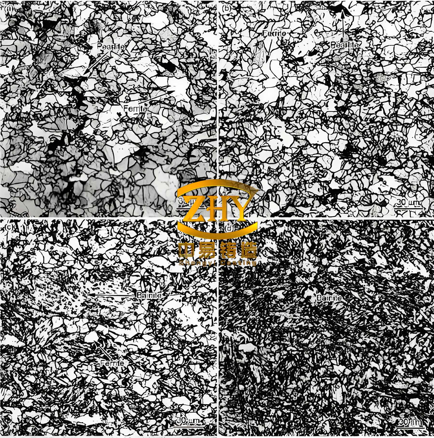
Metallographic examination revealed a microstructure with over 90% nodularity, graphite size of 6-7 (ASTM), and a predominantly ferritic matrix, as desired for high ductility. Non-destructive testing included 100% ultrasonic inspection according to EN12680-3 and magnetic particle inspection per EN1369. The casting achieved quality level 3 in both, indicating sound internal and surface integrity with no significant defects like shrinkage cavities, porosity, or cracks. The successful production of this massive spheroidal graphite cast iron platform underscores the effectiveness of the integrated approach.
The production of thick-section spheroidal graphite cast iron components demands a holistic strategy. The pit molding with core assembly proved robust and cost-effective. The bottom-gating system with a calculated ratio ensured calm filling and effective feeding. The wire feeding球化 treatment provided precise and reproducible magnesium addition with minimal loss and environmental impact. The复合强化孕育处理, involving multiple inoculation points, successfully countered fading in the large volume of iron, yielding a high and uniform nodule count. The use of simulation software allowed for predictive optimization, reducing trial-and-error costs. Strict control over chemistry, particularly low impurity elements and balanced球化 residues, was fundamental. The slow cooling after solidification mitigated residual stresses. In conclusion, this practice demonstrates that with meticulous process design, advanced metallurgical control, and rigorous quality checks, it is feasible to produce high-integrity, heavy-section spheroidal graphite cast iron castings meeting the demanding standards of modern heavy industry. The knowledge gained reinforces the versatility and reliability of spheroidal graphite cast iron for critical large-scale applications.
Further considerations for future productions could involve optimizing the chilling design using advanced heat transfer simulations, experimenting with novel孕育 alloys for even better fade resistance, and implementing real-time thermal monitoring during solidification to dynamically adjust cooling. The continuous improvement in the production of spheroidal graphite cast iron will undoubtedly support the development of even larger and more complex engineered components.