
The pursuit of efficient and cost-effective manufacturing processes for automotive components is a continuous endeavor in foundry engineering. Camshafts, as critical engine parts, have seen widespread adoption of spheroidal graphite iron due to its excellent combination of castability, machinability, strength, and wear resistance, often at a lower cost compared to forged steel. Among the various casting methods, iron mold coated sand casting is often cited as optimal for producing high-integrity spheroidal graphite iron camshafts, primarily due to the high cooling rate and mold rigidity it provides, which minimizes shrinkage porosity. However, this method requires significant initial investment in reusable iron molds, which are dedicated to specific part geometries and susceptible to thermal distortion over time, leading to increased lifecycle costs.
This investigation explores an alternative production route: shell mold casting for a high-strength grade of spheroidal graphite iron, specifically QT700-3 (minimum tensile strength 700 MPa, minimum elongation 3%). The objective is to develop a viable shell molding process that overcomes the inherent challenges of “mushy” solidification in spheroidal graphite iron, which typically leads to centerline shrinkage defects in axisymmetric sections like camshafts. The success of this process hinges on a synergistic approach involving advanced process simulation, meticulous mold design tailored to the thermal demands of the casting, and optimized metallurgical treatment to achieve the target microstructure and mechanical properties.
The target specifications for the spheroidal graphite iron camshaft were stringent. The mechanical properties required were a tensile strength (Rm) ≥ 700 MPa and an elongation at break (A) ≥ 3%. Microstructurally, the requirements included a graphite spheroidization grade ≥ 95%, a graphite nodule count ≥ 150 nodules/mm², a graphite size rating between 5 to 7 (according to relevant standards), a pearlite content ≥ 80%, with ferrite ≤ 15% and free carbides ≤ 5%.
Process Design and Numerical Simulation
The foundation of a sound casting process is robust design. For the camshaft, with a length of 376 mm, a major end diameter of Φ46 mm, and a base shaft diameter of Φ22 mm, a layout of two castings per mold was selected to ensure consistency and production efficiency. A gating system with a choke at the ingate (semi-closed system) was employed, with the ingate located at the large end of the camshaft. A feeder/riser was placed on the runner bar, and venting/slag collection heads were designed at the end of each cavity.
To proactively identify and mitigate potential defects, a full 3D numerical simulation of the filling and solidification processes was conducted using FLOW-3D CAST software. The system was discretized using hexahedral mesh elements with a size of 1.5 mm, resulting in approximately 4.3 million cells. The key material properties and boundary conditions for the simulation are summarized below:
| Parameter | Value / Description |
|---|---|
| Casting Material | QT700-3 (Database) |
| Liquid Density | 6.459 g/cm³ |
| Solid Density | 7.240 g/cm³ |
| Specific Heat | 780 J/(kg·K) |
| Thermal Conductivity | 38 W/(m·K) |
| Pouring Temperature | 1,350 °C |
| Mold Material | Precoated (Resin-Coated) Sand |
| Density × Specific Heat | 1.7×10⁶ J/(m³·°C) |
| Thermal Conductivity | 0.6 W/(m·K) |
| Initial Mold Temperature | 20 °C |
| Boundary Conditions | |
| Metal-Mold HTC | 1,000 W/(m²·K) |
| Metal-Air HTC | 300 W/(m²·K) |
The simulation yielded critical insights. The filling analysis indicated minimal surface defects such as slight air entrainment and oxide film accumulation at the end of the cavity, which could be addressed with adequate venting. The more significant finding was from the solidification analysis. It revealed that while solidification progressed sequentially from the surface to the core, isolated liquid pools formed in the thicker sections of the base shaft during the late stages. The feeding paths from the riser were prematurely cut off, leading to a high probability of shrinkage porosity along the central axis of these sections. This is a classic challenge in spheroidal graphite iron castings due to the long solidification range. The simulation predicted the exact location of these defects, which is visually represented in the results as areas of high porosity potential.
To counteract this, the primary process variable available in shell molding is the mold wall thickness, which directly governs the local cooling rate. The governing heat transfer equation during solidification can be simplified as:
$$ q = h \cdot A \cdot (T_{melt} – T_{mold}) + \frac{k_{mold}}{d_{mold}} \cdot A \cdot (T_{interface} – T_{ambient}) $$
where \( q \) is the heat flux, \( h \) is the interfacial heat transfer coefficient, \( A \) is the area, \( T \) are temperatures, \( k_{mold} \) is the thermal conductivity of the mold, and \( d_{mold} \) is the mold wall thickness. To increase heat extraction \( q \) from a specific region (the thick base shaft), one can effectively decrease the thermal resistance by reducing the mold wall thickness \( d_{mold} \). Consequently, the shell mold was designed with a non-uniform wall thickness: 14 mm at the critical thick sections of the base shaft, and a standard 18 mm for all other areas, including the cams and thinner shaft sections. A subsequent simulation confirmed that this modification accelerated the cooling in the problematic zones, allowing them to solidify in a more directional manner towards the riser, thereby eliminating the predicted centerline shrinkage.
Shell Mold Manufacturing and Core Production
The shell mold’s integrity is paramount. The properties of the precoated sand directly influence the final casting quality. The sand used in this study had the following characteristics:
| Property | Specification |
|---|---|
| Grain Fineness | 70/140 |
| Tensile Strength (Room Temp.) | ≥ 5.0 MPa |
| Hot Tensile Strength | ≥ 2.5 MPa |
| Flexural Strength (Room Temp.) | ≥ 10 MPa |
| Gas Evolution (850°C) | ≤ 16.5 mL/g |
Low gas evolution is particularly crucial to minimize gas-related defects in the casting. The shell molding process parameters were carefully controlled to achieve consistent mold strength and complete resin curing, which also minimizes gas generation during pouring.
| Process Parameter | Setting |
|---|---|
| Shooting Pressure | 0.06 MPa |
| Shooting Time | 4 s |
| Venting Time | 6 s |
| Curing Temperature | 190 – 210 °C |
| Curing Time | 100 – 120 s |
Adequate curing was visually confirmed by a tan/reddish-brown color on the shell surface. The final cured shell mold, featuring the thin-wall sections, was then ready for assembly and pouring.
Melting, Treatment, and Pouring of Spheroidal Graphite Iron
Achieving the QT700-3 specification requires precise control over chemistry and treatment. The base charge consisted of low-manganese steel scrap, with carbon levels adjusted using high-quality, low-sulfur graphite recarburizers. The chemical composition was designed to promote a predominantly pearlitic matrix while retaining sufficient ductility, accounting for the relatively slower cooling of shell molds compared to iron molds.
| Element | Target Range (wt.%) |
|---|---|
| Carbon (C) | 3.7 – 3.9 |
| Silicon (Si) | 2.2 – 2.6 |
| Manganese (Mn) | 0.5 – 0.7 |
| Phosphorus (P) | ≤ 0.06 |
| Sulfur (S) | ≤ 0.05 |
| Copper (Cu) | 0.8 – 0.9 |
Copper is a key alloying addition to promote and stabilize pearlite, which is essential for achieving the high strength in this grade of spheroidal graphite iron, especially under slower cooling conditions.
The treatment process was rigorously optimized. Melting was conducted in a medium-frequency induction furnace. For a 500 kg batch, the treatment temperature was maintained between 1,520 – 1,560 °C. The spheroidizing treatment was performed using the conventional sandwich method with a rare-earth magnesium ferrosilicon alloy (1.3 – 1.5% addition). Inoculation is critical for achieving a high nodule count and preventing carbide formation. A combined inoculation strategy was employed using a Si-Ca-Ba alloy (1.0 – 1.3% total addition): 40% as a base inoculation in the treatment ladle, 50% as a late stream inoculation during transfer, and the final 10% as a pouring stream inoculation. The pouring temperature was controlled within the range of 1,380 – 1,420 °C to ensure good fluidity while minimizing sand reaction and shrinkage tendencies.
Microstructural and Mechanical Performance Evaluation
The metallurgical quality of the shell-cast camshafts was assessed both on separately cast keel block samples and on samples taken from the camshaft body itself.
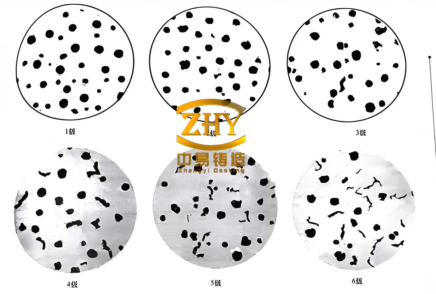
The microstructure of the spheroidal graphite iron was excellent. Graphite morphology showed a spheroidization grade of 1-2, with nodules being predominantly spherical and well-distributed. The nodule count was significantly higher than the minimum requirement. For instance, in the cam lobe area (faster cooling), the count exceeded 650 nodules/mm² with a size rating of 6-7, while in the base shaft (slower cooling), it was around 300-450 nodules/mm² with a size rating of 5-7. The matrix structure consisted of the targeted pearlite-ferrite mix. The cam lobe exhibited approximately 85% pearlite and 15% ferrite, whereas the base shaft showed about 95% pearlite and 5% ferrite. This variation is attributed to the higher nodule count in the cam, where the carbon-depleted zones around each graphite nodule more readily transform to ferrite during the eutectoid transformation. No free carbides or phosphide eutectic were observed. The relationship between local cooling rate (CR), nodule count (N_v), and ferrite content (F%) can be conceptually described as:
$$ N_v \propto f(CR, \text{Inoculation Potency}) $$
$$ F\% \approx k \cdot N_v^{1/3} + C $$
where \( k \) is a constant related to diffusion and \( C \) is a base ferrite level, explaining the higher ferrite in the cam lobe with its higher \( N_v \).
The mechanical properties, derived from the separately cast test bars, consistently met and often exceeded the QT700-3 specification, as tabulated below:
| Sample | Tensile Strength (MPa) | Elongation (%) | Pearlite (%) | Ferrite (%) | Nodule Count (nodules/mm²) |
|---|---|---|---|---|---|
| 1 | 750 | 3.1 | 90 | 10 | 528 |
| 2 | 715 | 3.2 | 90 | 10 | 687 |
| 3 | 720 | 3.4 | 85 | 10 | 752 |
| 4 | 735 | 3.3 | 85 | 10 | 670 |
| 5 | 795 | 3.2 | 95 | 5 | 425 |
| 6 | 813 | 3.15 | 95 | 5 | 455 |
This data conclusively proves that the shell mold casting process, when properly engineered, is fully capable of producing high-integrity spheroidal graphite iron components with demanding mechanical property requirements.
Analysis of Defects and Corrective Measures
During process development, several casting defects were encountered and systematically addressed:
1. Centerline Shrinkage: This was the primary defect, predicted by simulation and occurring in thick shaft sections. Root Cause: Isolated liquid pools forming due to the “mushy” solidification of spheroidal graphite iron, with interrupted feeding paths. Solution: Implementing a variable shell thickness (14 mm vs. 18 mm) to increase the local cooling rate, thereby promoting directional solidification and maintaining an open feeding channel to the riser for a longer duration. The effectiveness of this measure was validated by both simulation and physical casting trials.
2. Gas Porosity and Sand Inclusions: These defects appeared as surface or subsurface voids. Root Cause: High gas evolution from the mold, insufficient mold curing, loose sand, or inadequate metal filtration. Solution: Using a low-gas-evolution precoated sand; strictly controlling curing temperature and time to achieve full polymerization; thorough cleaning of shells; and implementing effective slag traps and ceramic foam filters in the gating system.
3. Surface Folds (Blisters) and Misruns: These manifest as irregular surface textures or incomplete filling. Root Cause: High viscosity of the molten iron, low fluidity, or high back-pressure in the mold cavity impeding flow. Solution: Optimizing the carbon equivalent to improve fluidity; increasing the pouring temperature within the defined range; and ensuring adequate venting at the extremities of the mold cavity to allow air to escape smoothly during filling. The flow of molten metal can be described by the Bernoulli principle with losses, and ensuring vents reduces the back-pressure term \( P_{back} \) in the simplified equation:
$$ h_{pour} = \frac{v^2}{2g} + \frac{P_{atm} – P_{back}}{\rho g} + h_{loss} $$
where a lower \( P_{back} \) facilitates easier filling.
Conclusions and Industrial Significance
This comprehensive study successfully demonstrates the feasibility of producing QT700-3 grade spheroidal graphite iron camshafts using the shell mold casting process. The key to this achievement lies in a holistic, scientifically grounded approach:
- Simulation-Driven Design: Numerical simulation was indispensable for predicting and eliminating the primary defect of centerline shrinkage. It guided the critical design decision to use a variable shell mold thickness, tailoring the cooling rate to the thermal needs of different sections of the casting.
- Metallurgical Compensation: Recognizing the slower cooling inherent to shell molds compared to iron molds, the chemical composition was adjusted, notably through a deliberate increase in copper content (0.8-0.9%), to robustly promote and stabilize the pearlitic matrix necessary for high strength.
- Enhanced Treatment: A robust three-stage inoculation practice was essential to achieve a high and uniform graphite nodule count, which directly contributes to mechanical strength, ductility, and the suppression of undesirable carbide phases.
- Process Control: Rigorous control over all parameters—from sand properties and shell curing to pouring temperature and metal treatment—was required to mitigate secondary defects like gas porosity and surface folds.
The final shell-cast camshafts consistently met all specified mechanical property (Rm ≥ 700 MPa, A ≥ 3%) and stringent microstructural requirements (nodule count, pearlite content, spheroidization grade). This process offers a compelling alternative to iron mold coated sand casting, particularly for medium-to-high volume production where the flexibility of shell molds and lower upfront tooling cost present significant economic advantages, provided the process is engineered with the insights described herein. This work expands the viable manufacturing portfolio for high-performance spheroidal graphite iron components.