
In my experience with large-scale casting projects, the design and production of critical components like punch discs for high-speed presses pose significant challenges. These discs, made from spheroidal graphite iron, require meticulous process planning to ensure structural integrity and performance. As a foundry engineer, I have been involved in developing casting processes for such heavy-duty parts, where the goal is to achieve defect-free castings with superior mechanical properties. Spheroidal graphite iron, known for its excellent strength and ductility, is the material of choice for these applications, but its casting requires careful control over composition, solidification, and feeding systems. In this article, I will detail our approach to designing and simulating the casting process for a spheroidal graphite iron punch disc, incorporating extensive use of tables and formulas to summarize key aspects.
The punch disc is a vital component in high-speed presses, with a complex geometry that includes peripheral slots for weight reduction and bottom holes for connectivity. Its large size—approximately 4,800 mm in diameter and 1,700 mm in height—and substantial weight of 38,000 kg make casting particularly demanding. The primary wall thickness is 220 mm, with localized hot spots at bearing seat roots, which can lead to shrinkage defects if not properly managed. The material specification is spheroidal graphite iron grade QT500-7, requiring tensile strength above 420 MPa, yield strength above 320 MPa, and elongation over 5%. Achieving these properties in a large casting necessitates a holistic process design that addresses chemical composition, molding techniques, and melt treatment. Spheroidal graphite iron’s tendency for oxidation and graphite degeneration in thick sections further complicates the process, emphasizing the need for robust simulation and validation.
Our process design began with a thorough analysis of the spheroidal graphite iron composition. Carbon equivalent (CE) is a critical parameter, as it influences fluidity and shrinkage behavior. For spheroidal graphite iron, we aim for a CE between 4.0% and 4.2%, calculated using the formula: $$CE = C + \frac{Si}{3}$$ where C and Si are the carbon and silicon contents in weight percent. This range ensures good castability while minimizing carbide formation. Based on this, we set the target carbon content at 3.5% and silicon at 2.0–2.4% after treatment. Phosphorus and sulfur are kept low to avoid detrimental effects; phosphorus should be below 0.02% to reduce segregation and carbide promotion, while sulfur is controlled below 0.015% to facilitate effective magnesium treatment. The residual magnesium content, crucial for spheroidization, is maintained between 0.035% and 0.055%, as higher levels can increase shrinkage porosity. Trace elements like antimony are added in minute amounts (0.005–0.01%) to enhance graphite nodule count and morphology, but excess can interfere with spheroidization. Table 1 summarizes the target chemical composition for the spheroidal graphite iron punch disc.
| Element | Pre-Treatment Range | Post-Treatment Range |
|---|---|---|
| C | 3.5–3.7 | 3.4–3.6 |
| Si | 1.4–1.5 | 2.0–2.4 |
| Mn | 0.35–0.45 | 0.35–0.45 |
| P | ≤ 0.02 | ≤ 0.02 |
| S | ≤ 0.01 | 0.006–0.01 |
| Cu | – | 0.5–0.8 |
| Sb | – | 0–0.01 |
| Mgres | – | 0.035–0.055 |
The molding process employed furan resin sand with a three-box design. The parting surface was selected to position the disc’s bottom face in the lower box, ensuring better density and reducing turbulence during filling. The gating system was designed as a bottom-pouring, semi-open type to promote smooth metal flow and minimize slag inclusion. Multiple ingates were distributed around the base to ensure uniform filling, and the cross-sectional area ratio was set as ΣSsprue : ΣSrunner : ΣSingate = 1 : 1.2 : 0.8, which can be expressed mathematically as: $$\frac{\Sigma S_{\text{sprue}}}{\Sigma S_{\text{runner}}} = 0.833 \quad \text{and} \quad \frac{\Sigma S_{\text{ingate}}}{\Sigma S_{\text{sprue}}} = 0.8$$ This ratio facilitates high flow rates while maintaining laminar flow. Chills were strategically placed at hot spots, such as the bearing seat roots, to accelerate cooling and reduce solidification time. The use of chills is critical for spheroidal graphite iron castings, as it helps prevent graphite degeneration and shrinkage porosity. The effectiveness of chills can be estimated using the modulus method, where the modulus M is given by: $$M = \frac{V}{A}$$ where V is the volume and A is the cooling surface area. For thick sections, chills increase the effective cooling area, thereby reducing the local modulus and promoting directional solidification.
Melting and treatment processes were tailored for spheroidal graphite iron. The melt was superheated to 1,500–1,550°C and held for 5–8 minutes to purify the iron. The tapping temperature was controlled at 1,430–1,460°C, and the pouring temperature was set at 1,300–1,330°C to balance fluidity and solidification time. Lower pouring temperatures shorten solidification time, which benefits graphite morphology in spheroidal graphite iron, but too low a temperature can lead to cold shuts. For spheroidization, a yttrium-based heavy rare earth spheroidizer was used via the sandwich method. The spheroidizer addition was 1.0–1.2% of the melt weight, with composition detailed in Table 2. The residual magnesium and rare earth contents are vital for maintaining nodule count; the relationship between sulfur and magnesium can be described as: $$[Mg]_{\text{res}} \propto \frac{1}{[S]}$$ meaning that lower sulfur allows for lower residual magnesium to achieve good spheroidization. Inoculation was performed multiple times using barium-containing and long-lasting inoculants to enhance graphite nucleation. The total inoculation addition was 0.6–0.8%, as shown in Table 3. The inoculation effect on graphite nodule count N can be modeled as: $$N = k \cdot [Si]_{\text{inoc}} \cdot e^{-t/\tau}$$ where k is a constant, [Si]inoc is the silicon from inoculant, t is time, and τ is the衰退 time constant.
| Type | RE | Mg | Si | Addition |
|---|---|---|---|---|
| Yttrium-based Heavy RE | 1.5–2.5 | 6–7 | 45 | 1.0–1.2 |
| Type | Si | Ca | Al | Ba | RE | Addition |
|---|---|---|---|---|---|---|
| Barium-containing | 70–75 | 1.5–2.0 | 1.0–2.0 | 1.0–2.0 | – | 0.5–0.6 |
| Long-lasting | 55–65 | – | – | – | 1.0–2.0 | 0.1–0.2 |
Simulation of the casting process was conducted using AnyCasting software to analyze filling and solidification. The model incorporated the gating system design, chill placements, and material properties of spheroidal graphite iron. The filling sequence simulation showed that metal entry was smooth, with no significant turbulence. At 12 seconds into filling, isolated liquid pockets were observed near ingates, but the time difference of 24 seconds between initial and final filling points ensured safety. The velocity field analysis indicated that at 40% filling, the average velocity within the casting was 51 cm/s, which is stable and minimizes erosion risks. Oxide formation simulation revealed that oxide content peaked at 4.2 g/cm³ in early stages but reduced to 3.58 g/cm³ by the end of filling, indicating low inclusion risk. Temperature field simulations confirmed that the temperature drop during filling was limited to 50°C, avoiding cold shuts. The solidification simulation predicted shrinkage-prone areas, which aligned with chill locations, validating our design. The solidification time tsolid can be estimated using Chvorinov’s rule: $$t_{\text{solid}} = k \cdot M^n$$ where k is a constant dependent on material and mold, M is the modulus, and n is an exponent typically around 2. For spheroidal graphite iron, controlling solidification time is key to preventing graphite flotation and degeneration.
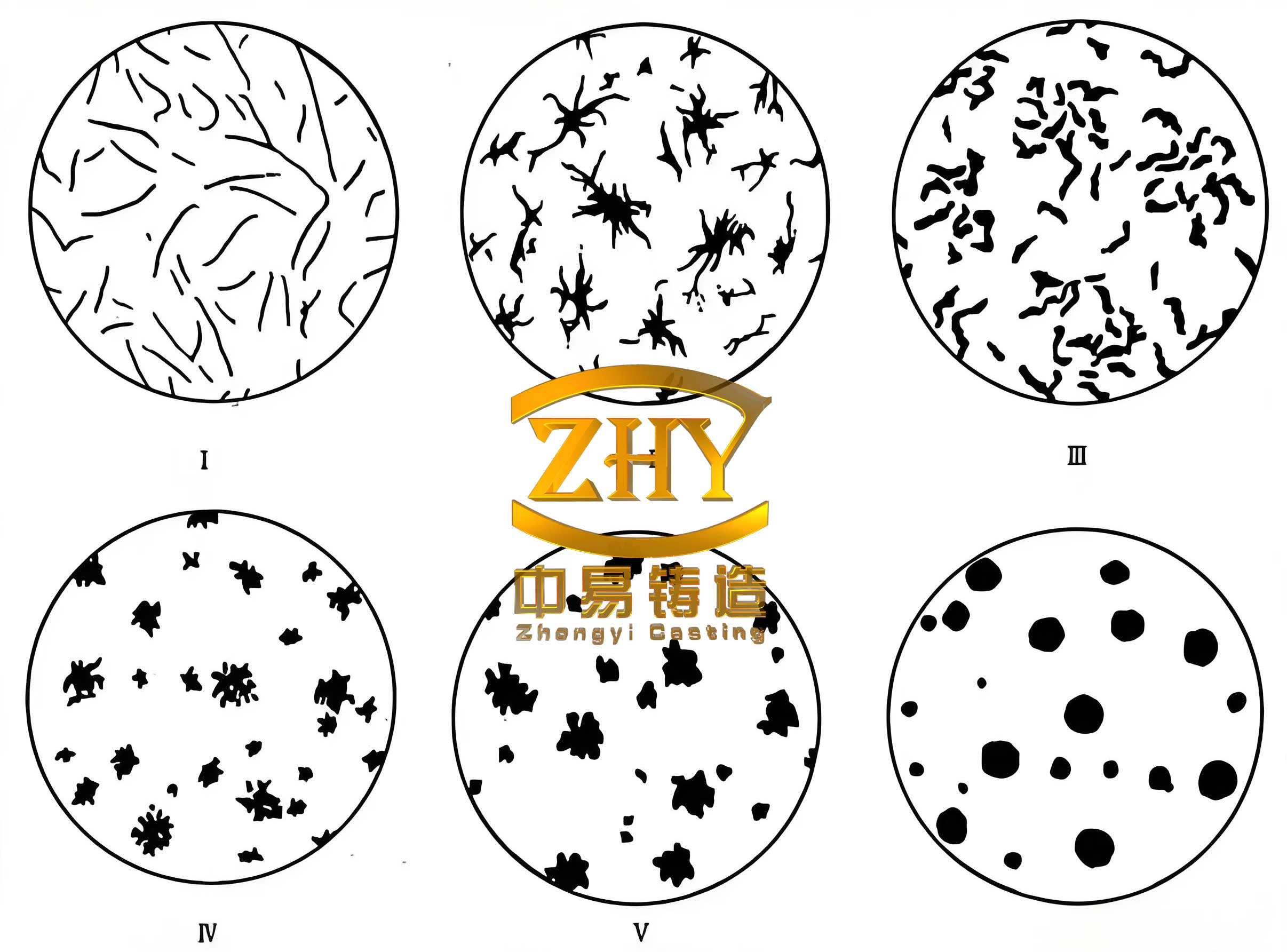
Production validation was carried out based on the simulated process. The actual chemical composition of the cast spheroidal graphite iron punch disc is shown in Table 4, closely matching our targets. Mechanical properties were evaluated using attached test samples, and the results are summarized in Table 5. The tensile strength exceeded 500 MPa, elongation was above 5%, and graphite morphology was rated at grade 6 with over 95% nodularity, meeting all specifications. Metallographic examination revealed well-formed spheroidal graphite with no signs of degeneration, as expected for properly treated spheroidal graphite iron. The casting was machined and inspected, showing no defects such as shrinkage or porosity, confirming the effectiveness of our process design. The successful production underscores the importance of integrated design and simulation for spheroidal graphite iron castings.
| Element | C | Si | Mn | P | S | Cu | Sb | Mgres |
|---|---|---|---|---|---|---|---|---|
| Content | 3.43 | 2.09 | 0.42 | 0.020 | 0.010 | 0.65 | 0.005 | 0.045 |
| Property | Requirement | Actual Value |
|---|---|---|
| Tensile Strength | ≥ 420 MPa | 535 MPa |
| Elongation | ≥ 5% | 5.5% |
| Graphite Grade | ≥ Grade 4 | Grade 6 |
| Nodularity | ≥ 90% | 95.42% |
In conclusion, the casting process for spheroidal graphite iron punch discs requires a comprehensive approach. Key learnings include maintaining a carbon equivalent of 4.0–4.2%, residual magnesium of 0.035–0.055%, and rare earth elements of 0.01–0.02% to optimize graphite formation in spheroidal graphite iron. Multiple inoculation with yttrium-based spheroidizers and controlled pouring temperatures between 1,300–1,330°C are essential to shorten solidification time and improve microstructure. The gating system should employ bottom pouring with dispersed ingates to ensure smooth filling, and chills must be used to enhance cooling at critical sections, reducing shrinkage defects. Simulation tools like AnyCasting provide valuable insights for validating designs before production. This process has been successfully applied to produce high-quality spheroidal graphite iron castings, demonstrating that meticulous planning and simulation can overcome the challenges of large-scale spheroidal graphite iron casting. Future work could explore advanced modeling techniques or alternative alloying strategies to further enhance the properties of spheroidal graphite iron components.
To further elaborate on the technical aspects, the modulus method for chill design can be expressed mathematically. For a cylindrical chill, the heat extraction rate Q is given by: $$Q = h \cdot A \cdot (T_m – T_0)$$ where h is the heat transfer coefficient, A is the interface area, Tm is the metal temperature, and T0 is the initial chill temperature. In spheroidal graphite iron, the latent heat of solidification L also plays a role, and the total heat to be removed H is: $$H = \rho \cdot V \cdot (C_p \cdot \Delta T + L)$$ where ρ is density, V is volume, Cp is specific heat, and ΔT is the temperature drop. By balancing Q and H, we can estimate chill dimensions required for effective cooling. Additionally, the nodule count in spheroidal graphite iron is influenced by inoculation efficiency, which can be represented as: $$N_v = N_0 \cdot e^{-k_d t} + \alpha \cdot [\text{Inoculant}]$$ where Nv is the volumetric nodule count, N0 is the initial count, kd is the衰退 rate, t is time, and α is a constant. These formulas highlight the scientific basis behind our empirical choices for spheroidal graphite iron treatment.
Moreover, the gating system design involves fluid dynamics principles. The flow rate Qf through the ingates can be calculated using Bernoulli’s equation: $$Q_f = C_d \cdot A \cdot \sqrt{2gh}$$ where Cd is the discharge coefficient, A is the cross-sectional area, g is gravity, and h is the metallostatic head. For spheroidal graphite iron, maintaining a low Reynolds number Re is crucial to avoid turbulence: $$Re = \frac{\rho v D}{\mu}$$ where v is velocity, D is hydraulic diameter, and μ is viscosity. Our design kept Re below 2000 to ensure laminar flow. The solidification shrinkage of spheroidal graphite iron, typically around 4–6%, necessitates adequate feeding, which is provided by the gating system during filling. The feeding efficiency η can be defined as: $$\eta = \frac{V_{\text{feed}}}{V_{\text{shrinkage}}}$$ where Vfeed is the volume of liquid fed and Vshrinkage is the shrinkage volume. In our process, η was kept above 1.2 through proper gating and chilling.
In summary, the success of casting spheroidal graphite iron punch discs hinges on a deep understanding of material science and process engineering. By leveraging simulations, empirical data, and theoretical models, we can produce defect-free spheroidal graphite iron castings that meet stringent performance criteria. This approach not only applies to punch discs but also to other large-scale spheroidal graphite iron components in heavy machinery, contributing to advancements in manufacturing technology for spheroidal graphite iron applications.