
In the realm of internal combustion engines, the crankshaft stands as a critical component, whose performance and durability directly dictate the operational lifespan and efficiency of the engine. For decades, forged steel was the material of choice for high-performance applications. However, with advancements in casting technology and metallurgical understanding, spheroidal graphite iron has emerged as a superior alternative, offering a compelling combination of high rigidity, exceptional fatigue strength, excellent wear resistance, and cost-effectiveness. My involvement in this field, particularly within our manufacturing initiative, focused on developing a as-cast, high-strength, and high-ductility spheroidal graphite iron crankshaft for a heavy-duty six-cylinder engine. The target specifications were stringent: a tensile strength no less than 850 MPa and an elongation at break no less than 4.5%, thereby achieving the grade QT850-4.5. This pursuit aimed to streamline production, eliminate energy-intensive heat treatment processes like normalizing to avoid distortion, and leverage the inherent advantages of spheroidal graphite iron casting.
The foundation for producing such a high-integrity spheroidal graphite iron component lies in meticulous control over every aspect of the manufacturing chain, from raw material selection to final quality verification. In our facility, we employed a 1-ton medium-frequency induction furnace for melting, which provides excellent control over temperature and composition. The casting process utilized the iron mold coated with sand (iron type sand-coated) technique. This process involves creating a thin layer (4-8 mm) of resin-coated sand on the inner cavity of a reusable metal mold. The advantages of this method for producing spheroidal graphite iron crankshafts are multifold and critical to achieving the desired properties. The high thermal conductivity of the metal mold allows for rapid heat extraction from the solidifying iron, promoting a fine and uniform microstructure. The mold possesses significant strength and rigidity, which, combined with the expansion of graphite during eutectic solidification, facilitates effective feeding and minimizes shrinkage porosity, effectively enabling self-feeding. This not only improves the yield and reduces scrap rates but also results in castings with excellent surface finish, often achieving a roughness of around 12.5 μm after shot blasting, and superior internal soundness.
The selection of raw materials for a high-strength, high-ductility spheroidal graphite iron is non-negotiable. The base iron must be of premium quality, preferably high-purity pig iron, to minimize the presence of trace elements that can promote the formation of degenerate graphite forms, such as chunky or exploded graphite, in the thermal centers of thick sections. Elements like silicon, manganese, sulfur, and phosphorus should be as low as practically possible. We mandated specifications for our charge materials: Si < 1.0%, Mn < 0.2%, S < 0.01%, and P < 0.04%. Particularly detrimental are anti-nodularizing elements like titanium, vanadium, tin, and tungsten. Titanium’s strong affinity for carbon and nitrogen can form carbides and nitrides that interfere with graphite spheroidization; therefore, its content was rigorously controlled below 0.04%. The total amount of trace elements (∑T) was kept below 0.1% to ensure graphite nodule stability. For steel scrap, we used high-quality low-alloy carbon steel with manganese content below 0.4% and similarly minimized levels of trace impurities.
The chemical composition of spheroidal graphite iron is the primary dictator of its microstructure and, consequently, its mechanical and casting properties. Designing the optimal composition was a cornerstone of our project. The interplay between elements can be described through various metallurgical relationships. A fundamental parameter is the carbon equivalent (CE), which gauges the combined graphitizing power of carbon and silicon. It is typically calculated as:
$$ CE = \%C + \frac{1}{3}\%Si $$
For our spheroidal graphite iron, we targeted a CE in the range of 4.4% to 4.5%. A higher CE improves fluidity, reduces shrinkage tendency, and promotes a larger number of smaller, rounder graphite nodules. However, exceeding the upper limit risks graphite flotation. Our chosen range balanced castability with microstructural control.
| Element | Role in Spheroidal Graphite Iron | Target Range (wt.%) | Rationale & Metallurgical Effect |
|---|---|---|---|
| Carbon (C) | Primary Graphite Former | 3.6 – 3.8 | High carbon increases graphite nodule count, refines structure, improves density, but must avoid flotation. Graphite volume fraction $V_g$ can be approximated from composition and cooling rate. |
| Silicon (Si) | Strong Graphitizer, Strengthener | Final: 2.1 – 2.5 | Promotes graphite formation, increases ferrite. Added via inoculation. High Si increases nodule count and roundness but can embrittle at very high levels. The final content is a sum of base and inoculated silicon. |
| Manganese (Mn) | Pearlite Stabilizer (Weak) | < 0.4 | Minimized due to its strong segregation tendency to cell boundaries, where it can form carbides and reduce toughness. Not actively added. |
| Phosphorus (P) | Impurity, Forms Low-Melting Phosphides | < 0.04 | Highly detrimental. Forms brittle, continuous phosphide networks at grain boundaries, severely reducing ductility and impact strength. Controlled via raw materials. |
| Sulfur (S) | Anti-Nodularizer | Base: 0.015-0.020 Post-treatment: < 0.01 | Must be removed via Mg treatment. A minimal residual is beneficial for nucleation sites (MgS). The reaction is: $ Mg + S \rightarrow MgS $. |
| Magnesium (Mg) | Spheroidizing Agent | Residual: 0.035 – 0.045 | Essential for converting flake graphite to spheroids. Excess Mg increases carbides and shrinkage. Absorption efficiency $\eta_{Mg}$ is low (~30%). |
| Rare Earths (RE) | Spheroidizing Aid, Counteracts Impurities | Residual: 0.01 – 0.02 | Neutralizes tramp elements like Pb, Sb, Bi. Also aids nucleation. Usually added with Mg in the spheroidizer. |
| Copper (Cu) | Pearlite Promoter, Strengthener | 0.7 – 0.8 | Exhibits negative segregation. Promotes pearlite formation during eutectoid transformation, enhancing strength with minimal impact on graphitization. |
| Molybdenum (Mo) | Carbide Former, Solid Solution Strengthener | 0.15 – 0.20 | Strong pearlite refiner and hardenability agent. Positively segregates. Increases strength but must be controlled to maintain ductility. Effect on yield strength $\sigma_y$ is significant. |
| Nickel (Ni) | Graphitizer, Pearlite Refiner | 0.2 – 0.4 | Negative segregation. Promotes graphite formation, refines pearlite, reduces section sensitivity, and improves toughness. |
The comprehensive target composition for our spheroidal graphite iron melt is summarized below, differentiating between the base iron analysis and the final treated metal.
| Stage | C | Si | Mn | P | S | Mg | RE | Mo | Ni | Cu |
|---|---|---|---|---|---|---|---|---|---|---|
| Base Iron | 3.6-3.8 | 1.3-1.4 | 0.3-0.4 | < 0.03 | 0.015-0.020 | – | – | 0.15-0.20 | 0.2-0.4 | – |
| Treated Iron | – | 2.1-2.5 | – | – | < 0.01 | 0.035-0.045 | 0.01-0.02 | – | – | 0.7-0.8 |
The melting and treatment process was a carefully choreographed sequence. We charged the furnace with the selected high-purity pig iron and low-manganese steel scrap. To achieve the target carbon content while using steel scrap, we employed high-quality graphite-based recarburizers. A crucial preprocessing step involved the addition of silicon carbide (SiC). This serves as a potent preconditioner; it dissolves in the iron melt, providing nascent silicon and carbon which act as substrates for later graphite nucleation, effectively increasing the eutectic cell count. The alloying elements molybdenum and nickel were added to the molten bath well before tapping, ensuring complete dissolution and homogenization.
Tap temperature was critical. We superheated the iron to approximately 1540°C and held it for 2-3 minutes. This practice helps in refining the melt, reducing gas content, and allowing inclusions to float out, thereby purifying the spheroidal graphite iron. The slag was thoroughly skimmed before tapping into the treatment ladle.
The spheroidizing and inoculation treatments are the heart of producing high-quality spheroidal graphite iron. We used the sandwich method (a variant of the pouring-in method) for spheroidization. The treatment ladle, with a capacity matching our furnace, had a well-shaped pocket. We placed the spheroidizing alloy in this pocket and covered it with a pre-weighed amount of primary inoculant. The spheroidizer was a magnesium-ferrosilicon alloy containing 5-7% Mg and 2-3% rare earths. The addition rate was carefully calculated based on the initial sulfur content and desired residual magnesium, typically between 1.1% and 1.3% of the iron weight. The reaction, though vigorous, is essential:
$$ [Mg] + [S] \rightarrow (MgS) $$
$$ 3[Mg] + 4[O] \rightarrow (Mg_3N_4) $$
The efficiency of magnesium recovery, $\eta_{Mg}$, is governed by factors like temperature and slag cover, and we accounted for this in our calculations.
Inoculation was performed in three stages to combat fade and ensure a high nodule count. Primary inoculation occurred during the tap; the stream of iron was used to carry and mix the inoculant placed over the spheroidizer. We used a proprietary barium-containing长效 (long-lasting) inoculant with a composition of 68-72% Si, 1-2% Ca, and 3-6% Ba, sized between 3-8 mm. The addition was 0.6-0.7%. A secondary, post-inoculation was sometimes performed during transfer. The most critical was the late-stream or instantaneous inoculation at the pouring lip. For this, we used a fine-grade (0.2-0.7 mm) inoculant of similar type, added at 0.1-0.13% of the metal stream weight. This last-minute introduction of nucleation sites is vital for generating a large number of small, well-formed graphite spheroids in the final spheroidal graphite iron casting. The effect of inoculation on nodule count $N_v$ can be modeled as a function of time and inoculant potency.
Process control parameters were strictly monitored. The “pour window”—the time from the end of spheroidizing treatment to the completion of pouring—was limited to 8-10 minutes. This minimizes magnesium fade and potential re-sulfurization from slag interaction. Cooling rate is another critical factor for achieving the desired as-cast pearlitic-ferritic matrix. The iron mold sand-coated process inherently provides rapid cooling. We optimized the mold design and cooling parameters to ensure a cooling curve that suppresses carbide formation while promoting a fine pearlitic matrix. The solidification time $t_s$ for a section of thickness $d$ in such a mold can be estimated by:
$$ t_s \propto \frac{d^n}{K} $$
where $K$ is the mold’s thermal diffusivity and $n$ is an exponent. Early shakeout was practiced as soon as the casting solidified sufficiently to withstand handling, further accelerating cooling through the eutectoid transformation range to refine the pearlite.
Quality verification was conducted on samples extracted from the crankpins and journals of the actual castings, ensuring the results were representative of the component’s performance. We employed multiple analytical techniques. Chemical composition was verified using optical emission spectrometry. The mechanical properties were the ultimate test. Tensile tests were performed on separately cast test bars conforming to standard geometries but also on machined specimens from the casting body itself. Hardness was measured on the fillet areas. Metallographic examination provided insights into the microstructure that governed these properties.
The results from five different casting batches, sampled from the body, are presented below. They unequivocally demonstrate the success of our methodology in producing a consistent, high-performance spheroidal graphite iron.
| Sample ID | Tensile Strength (MPa) | Elongation (%) | Hardness (HB) |
|---|---|---|---|
| Body-1 | 873 | 5.4 | 270 |
| Body-2 | 899 | 5.6 | 272 |
| Body-3 | 887 | 5.6 | 272 |
| Body-4 | 880 | 5.6 | 278 |
| Body-5 | 899 | 5.0 | 285 |
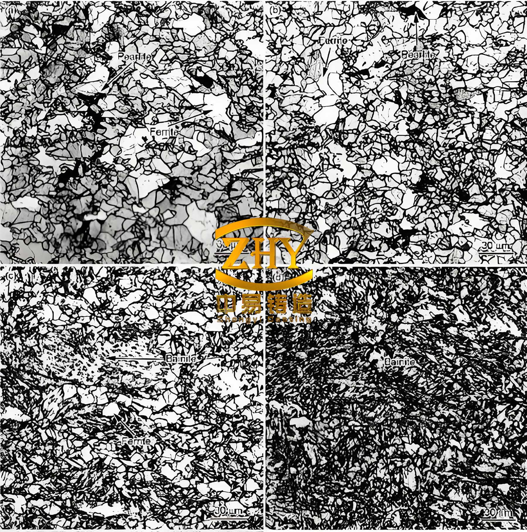
All samples comfortably exceeded the minimum requirements of 850 MPa tensile strength and 4.5% elongation. The hardness values were in an acceptable range for machinability and service. The metallographic analysis revealed a microstructure characteristic of high-quality spheroidal graphite iron: graphite spheroids of size 6 (ASTM) with a nodularity rating of 2 (excellent), uniformly dispersed in a matrix of approximately 95% fine pearlite. The amounts of free carbides and phosphide eutectic were both below 0.05%, which is crucial for the achieved ductility. The relationship between microstructure and tensile strength in pearlitic spheroidal graphite iron can be approximated by a rule-of-mixtures model considering the strengths of the metallic matrix and the graphite:
$$ \sigma_{UTS} \approx V_m \sigma_m + V_g \sigma_g $$
where $V_m$ and $V_g$ are the volume fractions of the matrix and graphite, and $\sigma_m$ and $\sigma_g$ are their respective strengths. Since graphite’s strength is negligible, the matrix strength, predominantly from the fine pearlite, is the key contributor, enhanced by solid solution strengthening from Cu, Mo, and Si.
In conclusion, the successful production of a heavy-duty, as-cast QT850-4.5 crankshaft from spheroidal graphite iron is a testament to a holistic and controlled approach. Several key factors were identified as indispensable. First, the uncompromising selection of high-purity raw materials forms the bedrock for achieving consistent and high-performance spheroidal graphite iron. Second, the precise design of chemical composition, balancing graphitizing elements with pearlite promoters and solid solution strengtheners like copper, molybdenum, and nickel, is paramount. This can be expressed as an optimization problem: maximizing $f(\sigma_{UTS}, \delta)$ subject to constraints on $[C]$, $[Si]$, $[Mg]$, etc., and phase stability criteria. Third, the implementation of a robust and multi-stage inoculation practice is critical to generate a high nodule count, which refines the structure and improves mechanical properties. The efficacy of inoculation can be related to the undercooling $\Delta T$ and the density of heterogeneous nuclei $N_0$. Fourth, the adoption of the iron mold sand-coated casting process provided the necessary rapid and directional solidification conditions to achieve a sound, dense casting with a fine microstructure without resorting to post-casting heat treatment. Finally, stringent process controls over melting temperature, treatment timing, and cooling dynamics ensured the reproducibility of the desired properties batch after batch. This project demonstrates that through scientific understanding and precise engineering, spheroidal graphite iron can be tailored to meet the demanding requirements of heavy-duty power train components, offering a reliable and cost-effective alternative to forged steel. Future work may involve further refinement of alloying strategies, exploration of alternative spheroidizing/inoculating agents, and the application of computational modeling to predict solidification and microstructure evolution in complex geometries like crankshafts, pushing the boundaries of what is achievable with advanced spheroidal graphite iron castings.