
The continuous evolution of rail transit technology places ever-increasing demands on material performance, particularly in the pursuit of vehicle lightweighting. Reducing the weight of components directly contributes to lower energy consumption and enhanced operational efficiency. Traditionally, rail transit castings have utilized lower-grade spheroidal graphite iron, such as QT400 to QT600 grades. While serviceable, these materials offer limited potential for significant weight reduction without compromising mechanical integrity. This research focuses on the development and implementation of a high-grade Austempered Ductile Iron (ADI), specifically targeting the QT800-10 specification, for the production of a complex rail transit housing casting. The study encompasses a holistic approach, integrating computational simulation for robust process design, strategic alloying for microstructural control, and precise heat treatment to achieve the desired superior combination of strength and ductility. The successful realization of this component demonstrates a viable pathway for advanced spheroidal graphite iron in demanding structural applications.
The target component in this investigation is a structural housing with a mass of 36.7 kg. Its geometry presented significant challenges, featuring highly variable wall thicknesses ranging from a minimum of 9 mm to a maximum of 58 mm. This non-uniformity is a primary concern for both the casting process, where it promotes differential solidification and shrinkage defects, and the subsequent heat treatment, where it can lead to inconsistent transformation kinetics and mechanical properties. A detailed structural analysis was therefore the critical first step in designing a manufacturable and high-performance component.
The foundation of any high-quality spheroidal graphite iron component is a meticulously designed chemical composition. The target mechanical properties for the ADI material, conforming to EN-GJS-800-10, required a tensile strength exceeding 800 MPa, a yield strength above 500 MPa, and a minimum elongation of 10%, accompanied by a Brinell hardness between 260-320 HBW. To achieve this, the chemical strategy aimed to ensure excellent graphitization potential, high hardenability for the austempering transformation, and minimal embrittling elements. Key composition ranges were established for both the furnace melt and the final, inoculated casting, as detailed in Table 1. Notably, the final silicon content was elevated to promote ferrite formation during solidification and to stabilize austenite during heat treatment, while controlled additions of copper were included to enhance hardenability, especially in the thicker sections of the casting.
| Stage | C | Si | Mn | P (max) | S | Cu | Mg |
|---|---|---|---|---|---|---|---|
| Pre-Furnace | 3.85-3.95 | 1.90-2.00 | 0.3-0.5 | 0.05 | 0.006-0.018 | 0.4-0.7 | – |
| Final Casting | 3.60-3.80 | 2.35-2.55 | 0.3-0.5 | 0.05 | 0.006-0.018 | 0.4-0.7 | 0.035-0.055 |
A robust casting process is paramount for producing sound castings free from shrinkage porosity, which would be fatal to the high-performance goals. An initial process was designed for a two-cavity mold on a high-pressure molding line. The gating system employed a pressurized design with filters to ensure smooth, non-turbulent filling. The key challenge was feeding the heavy sections. Based on Chvorinov’s rule and the modulus method, risers were placed to promote directional solidification. The feeder size is typically calculated using the modulus relationship:
$$ M_{riser} = 1.2 \times M_{casting} $$
where $M$ represents the modulus (Volume/Surface Area ratio). This ensures the riser remains molten longer than the casting section it is intended to feed.
To validate and optimize this initial design, MAGMA solidification simulation software was employed. The system was discretized into over 450,000 elements, and the simulation parameters were set as shown in Table 2. The initial simulation revealed a critical issue: isolated liquid pools, or “hot spots,” persisted within the thickest sections of the casting, indicating a high risk of shrinkage porosity. The existing risers were insufficient in their feeding range to compensate for the solidification shrinkage in these isolated thermal centers.
| Parameter | Setting |
|---|---|
| Casting Material | QT800 (ADI) |
| Mold Material | Silicate-Bonded Sand |
| Pouring Temperature | 1400 °C |
| Pouring Time | 10 s |
| Sand Temperature | 25 °C |
The solution was to strategically implement chills (metallic inserts) within the mold cavity adjacent to the thick sections. Chills act as heat sinks, rapidly extracting heat and locally altering the solidification sequence. This creates a more favorable temperature gradient, extending the effective feeding range of the risers and promoting directional solidification toward them. The design of a chill considers its ability to absorb the latent heat of fusion from the adjacent metal. A simplified approach to sizing involves its thermal mass:
$$ \delta = \frac{G}{\rho \times A} $$
where $\delta$ is a characteristic dimension related to chilling power, $G$ is the mass of the chill, $\rho$ is its density, and $A$ is the contact area with the casting. Two sizes of steel chills were designed and placed in the drag mold at the problematic locations.
Re-running the simulation with the optimized process including chills showed a dramatic improvement. The thermal analysis confirmed that the last points to solidify were now strategically located within the risers, and the previously identified internal hot spots were completely eliminated. The final shrinkage porosity prediction showed no defects within the casting body, verifying the efficacy of the chill-aided feeding system. This step was crucial not only for soundness but also for ensuring a more homogeneous microstructure in the heavy sections, which is vital for consistent response to subsequent heat treatment in this spheroidal graphite iron component.
Following the production of sound castings, the focus shifted to optimizing the metallurgical recipe to achieve the target austempered microstructure and properties. Three distinct alloying and inoculation trials were conducted, as summarized in Table 3. The goal was to refine the balance of hardenability elements (Mn, Cu) and graphite nucleation agents (Bi inoculant) to achieve the optimal combination of strength and ductility in the final ADI state.
| Trial | C | Si | Mn | Cu | Bi-Inoculant |
|---|---|---|---|---|---|
| 1 | 3.75 | 2.35 | 0.49 | 0.66 | – |
| 2 | 3.69 | 2.52 | 0.47 | 0.53 | 0.10 |
| 3 | 3.65 | 2.52 | 0.38 | 0.44 | 0.15 |
All castings from the trials underwent a standardized two-stage austempering heat treatment. First, they were austenitized in the temperature range of 860-920°C for 2-3 hours to achieve a homogeneous, carbon-saturated austenitic matrix. Subsequently, they were rapidly quenched into a salt bath maintained at 350-400°C, where they were held isothermally for 1-2 hours. During this hold, the metastable austenite transforms into the characteristic “ausferrite” microstructure—a fine, acicular mixture of ferrite and high-carbon, stabilized austenite. This microstructure is the source of the exceptional mechanical properties of ADI. The cooling curve for this process can be conceptually described, showing the avoidance of the pearlite “nose” on the Time-Temperature-Transformation diagram, which is critical for high-strength spheroidal graphite iron.
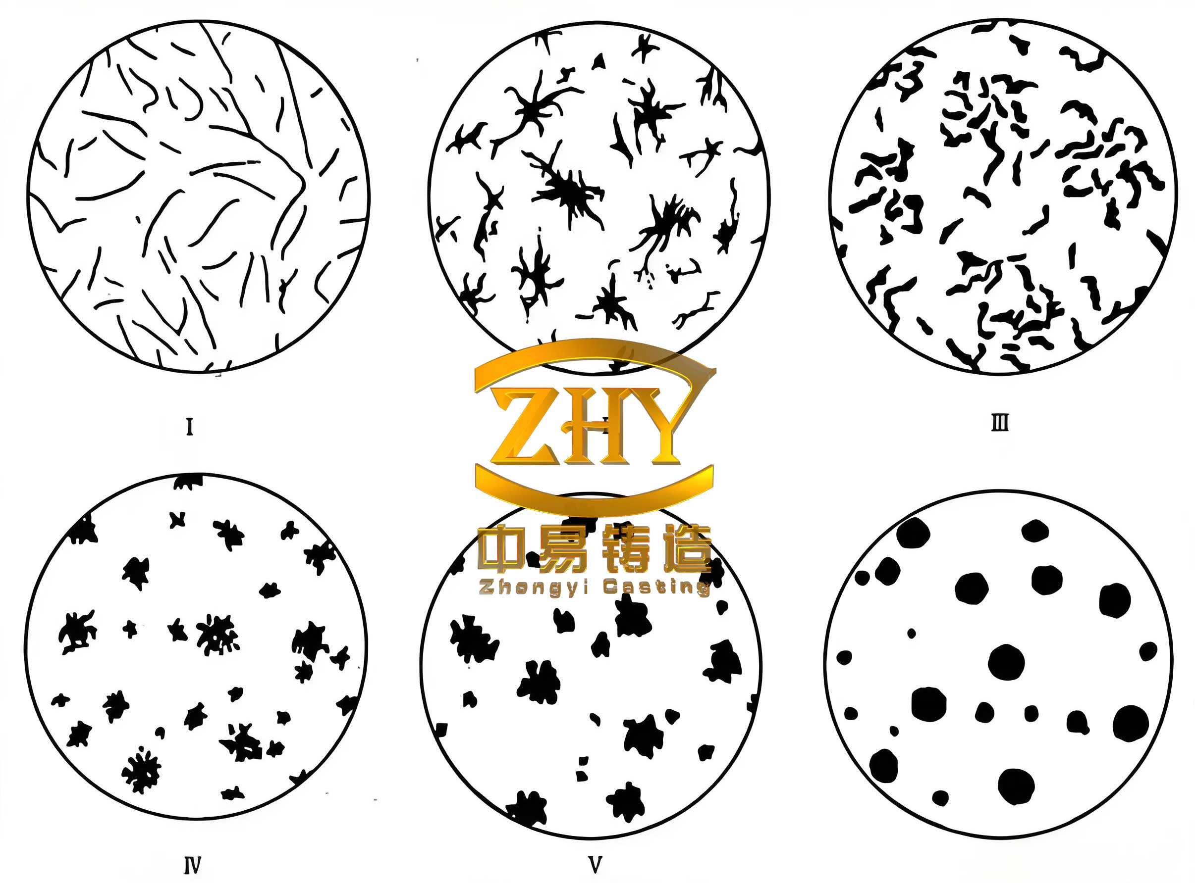
Specimens from each trial were taken from defined locations on the castings and subjected to full metallurgical evaluation. The results, including as-cast graphite characteristics and final ADI mechanical properties, are consolidated in Table 4. The performance progression across the trials is clear. Trial 1, with high Mn and Cu but no specialized inoculant, suffered from a low nodularity of 80%, the presence of degenerate (compacted/vermicular) graphite, and a low graphite nodule count. Consequently, despite having full ausferrite after heat treatment, its elongation was only 6%, far below the 10% target, although strength was borderline acceptable.
| Trial | Nodularity (%) | Graphite Count (nodules/mm²) | Austenitized Matrix (%) | Tensile Strength, Rm (MPa) | Yield Strength, Rp0.2 (MPa) | Elongation, A (%) | Hardness (HBW) |
|---|---|---|---|---|---|---|---|
| 1 | 80 | 166 | 100 | 770-801 | 487-502 | 6.0-6.5 | 318-321 |
| 2 | 90 | >307 | 100 | 897-918 | 572-581 | 10.5-13.5 | 309 |
| 3 | 95 | 345 | 100 | 971-984 | 602-610 | 16.5-20.0 | 293-296 |
The introduction of a bismuth-containing inoculant in Trial 2 marked a significant improvement. The nodularity increased to 90%, the graphite nodule count more than doubled, and degenerate graphite was eliminated. This refined and healthier graphite structure directly translated to a dramatic boost in ductility (exceeding 10%) while maintaining high strength. Trial 3 further optimized the system by slightly reducing the Mn and Cu content (maintaining sufficient hardenability) and increasing the bismuth inoculant addition to 0.15 wt.%. This yielded the best overall results: superb nodularity of 95%, the highest graphite nodule count of 345/mm², and a mechanical property profile that not only met but significantly exceeded the QT800-10 specification, achieving a tensile strength near 980 MPa with an exceptional elongation of 20%.
The underlying metallurgical principles are key. The Carbon Equivalent (CE) plays a fundamental role in defining the solidification behavior and graphite formation in spheroidal graphite iron. It is calculated as:
$$ CE = \%C + \frac{\%Si + \%P}{3} $$
For the successful Trial 3 composition, the CE was approximately 4.5, which is in an optimal range for ensuring a fully graphite microstructure without excessive carbides. The reduction of manganese, a mild carbide promoter and segregating element, minimized the risk of intercellular carbides that embrittle the matrix. Copper enhanced hardenability without strongly promoting pearlite. Most crucially, the bismuth-based inoculant profoundly refined the graphite phase. By providing a high density of potent nucleation sites, it increased the nodule count, improved sphericity, and prevented graphite degeneration. This refined graphite structure results in a more homogeneous stress distribution under load, delays crack initiation, and allows for greater plastic deformation of the ausferritic matrix, thereby synergistically increasing both strength and ductility. The final, optimized spheroidal graphite iron composition demonstrated that peak performance is not achieved by maximizing individual alloying elements, but by optimizing their synergistic interplay to control microstructure at multiple scales.
In conclusion, this comprehensive development program successfully engineered a high-performance austempered spheroidal graphite iron casting for a demanding rail transit application. The integration of computational simulation (MAGMA) was instrumental in designing and validating a casting process that utilized strategic chilling to eliminate shrinkage defects in a complex, variable-section geometry. The metallurgical investigation systematically revealed the critical importance of graphite morphology control through inoculation. The optimal composition, featuring 3.65% C, 2.52% Si, 0.38% Mn, 0.44% Cu, and 0.15% bismuth-containing inoculant, produced a casting with exceptional nodularity and graphite nodule count. After a controlled two-stage austempering heat treatment, this microstructure transformed into a high-quality ausferrite, yielding mechanical properties that surpassed the QT800-10 requirements, most notably achieving an outstanding balance of very high strength (≈980 MPa) and high ductility (≈20% elongation). This work underscores that advancing the application of spheroidal graphite iron into new, lightweight structural domains requires a fully integrated approach—merging advanced process simulation, precise alloy design focused on graphite engineering, and meticulous heat treatment control to unlock the full potential of this versatile and high-performance material.