
In my extensive experience within the foundry industry, the production of heavy-section spheroidal graphite iron components represents a pinnacle of technical challenge and precision engineering. This article details the first-hand account of manufacturing an oversize spheroidal graphite iron butterfly plate, a casting weighing 24 tons with a maximum wall thickness exceeding 100 mm. The successful execution of this project hinged on a holistic strategy encompassing advanced simulation, meticulous metallurgical control, and rigorous quality assurance, all aimed at harnessing the inherent benefits of spheroidal graphite iron for demanding valve applications.
The evolution of valve technology has been significantly influenced by material advancements. While cast and forged steels dominated early constructions, the mid-20th century saw the rise of spheroidal graphite iron as a formidable alternative. Its unique microstructure, characterized by graphite spheroids within a metallic matrix, confers a remarkable combination of strength, ductility, and damping capacity. For large-scale infrastructure like hydroelectric power stations, where butterfly valves control massive fluid flows, the economic and performance advantages of spheroidal graphite iron are particularly compelling. However, translating these advantages into a reliable, thick-walled casting like a butterfly plate demands overcoming inherent solidification challenges, such as graphite degeneration, segregation, and shrinkage porosity, which are exacerbated by slow cooling rates.
The journey began with the casting’s digital twin. Employing ProCAST simulation software was not merely a preliminary step but an iterative investigative process. We created a virtual model of the butterfly plate, incorporating the designed gating system, insulating risers, and strategically placed chills. The software solved the fundamental heat transfer and fluid flow equations governing solidification. The energy equation, central to the simulation, is expressed as:
$$ \rho C_p \frac{\partial T}{\partial t} = \nabla \cdot (k \nabla T) + \rho L \frac{\partial f_s}{\partial t} $$
where $\rho$ is density, $C_p$ is specific heat, $T$ is temperature, $t$ is time, $k$ is thermal conductivity, $L$ is latent heat, and $f_s$ is the solid fraction. Multiple simulation runs allowed us to visualize the progressive solidification fronts and predict the location of potential shrinkage defects with high confidence. The final optimized layout showed that the thermal centers, and thus the last points to solidify, were successfully shifted into the insulated risers, leaving the casting body sound.
The gating system design was governed by principles of fluid dynamics to ensure a non-turbulent, oxide-minimizing fill. We adopted a bottom-gating design with a well-calibrated ratio of choke, runner, and ingate areas. The cross-sectional areas were calculated based on the intended pouring time and Bernoulli’s principle for incompressible flow. The relationship between flow rate, area, and velocity is given by:
$$ Q = A \cdot v $$
where $Q$ is the volumetric flow rate, $A$ is the cross-sectional area, and $v$ is the flow velocity. To prevent mold erosion and air aspiration, the velocity at the ingates was kept below a critical threshold, typically 0.5 m/s for resin-bonded sands. The design criteria for the gating system ratios were established as:
$$ \Sigma A_{choke} : \Sigma A_{runner} : \Sigma A_{ingate} = 1 : 1.23 : 1.8 $$
This progressive enlargement helps in reducing flow velocity and promoting a laminar fill. Furthermore, the use of ceramic foam filters within the runner system provided an effective barrier for non-metallic inclusions, crucial for maintaining the cleanliness of the spheroidal graphite iron melt.
The management of solidification is paramount for thick-section spheroidal graphite iron. Chills, made of cast iron or copper, were employed adjacent to the thickest sections of the butterfly plate. Their function is to extract heat rapidly, creating a steep thermal gradient and promoting directional solidification towards the risers. The heat extraction rate of a chill can be approximated using the concept of interfacial heat transfer coefficient (IHTC). The heat flux $q$ across the mold-metal interface is:
$$ q = h (T_{metal} – T_{chill}) $$
where $h$ is the IHTC, a complex parameter dependent on surface roughness, air gap formation, and material properties. By using chills, we effectively increased the local cooling rate, which is vital for maintaining a high nodule count and preventing the formation of degenerate graphite forms like chunky or exploded graphite. The target was to keep the solidification time for any substantial thermal mass below 120 minutes, as prolonged times in the critical temperature range for graphite formation (approximately 1150°C to 950°C) favor graphite coarsening and ferrite ring formation around nodules.
| Parameter | Symbol/Formula | Target Value/Range | Rationale |
|---|---|---|---|
| Modulus (Volume/Surface Area) | $M = V/A$ | ~50 mm (for thick sections) | Determines local solidification time; used for riser sizing. |
| Riser Sizing (Modulus Method) | $M_{riser} = 1.2 \times M_{casting}$ | Calculated per thermal center | Ensures riser remains liquid longer than the casting section it feeds. |
| Pouring Temperature | $T_{pour}$ | 1320 – 1360 °C | Balances fluidity, shrinkage, and dross formation. |
| Target Solidification Time | $t_s$ | < 120 min | Limits time for graphite degeneration and segregation. |
| Chill Design Factor | $F_c = (k\rho C_p)_{chill} / (k\rho C_p)_{sand}$ | >> 1 | Quantifies the relative chilling power compared to the sand mold. |
The foundation of high-quality spheroidal graphite iron lies in its chemistry. Our compositional strategy was meticulously crafted to navigate the narrow window that ensures good castability, robust mechanical properties, and structural integrity in heavy sections. The carbon equivalent (CE) was targeted near the eutectic point to maximize fluidity and the beneficial graphite expansion pressure that counteracts shrinkage. The CE is calculated as:
$$ CE = C + \frac{1}{3}(Si + P) $$
We aimed for a CE between 4.25 and 4.35. Silicon content was carefully controlled; while it is a potent graphitiser and ferrite stabilizer, its segregation tendency and potential to increase the ductile-to-brittle transition temperature necessitated an upper limit. Manganese, a strong pearlite promoter and prone to severe intercellular segregation in slow-cooling conditions, was minimized. Phosphorus and sulfur, notorious for forming brittle intermetallic phases and consuming nodulizing elements, were kept at ultra-low levels.
| Element | Target (wt%) | Upper Limit (wt%) | Metallurgical Rationale in Heavy-Section Spheroidal Graphite Iron | Potential Defect from Excess |
|---|---|---|---|---|
| Carbon (C) | 3.5 | 3.6 | Primary driver for fluidity and graphite expansion. High carbon equivalent reduces shrinkage tendency. | Graphite flotation in upper sections of the casting. |
| Silicon (Si) | 2.4 | 2.5 | Promotes ferrite, increases yield strength. Must be balanced to avoid excessive hardening of matrix and promoting spheroidization decay. | Formation of chunky graphite, reduced impact toughness at low temperatures. |
| Manganese (Mn) | 0.2 | 0.3 | Minimized to reduce segregation at cell boundaries and the risk of intercellular carbides. | Formation of (Fe,Mn)3C carbides at grain boundaries, drastically reducing ductility. |
| Sulfur (S) | 0.015 | 0.02 | Low base sulfur is essential for efficient magnesium utilization and clean metal. | Excessive MgS slag formation, poor graphite nodularity, pinhole defects. |
| Phosphorus (P) | 0.03 | 0.04 | Kept low to prevent the formation of steadite (Fe3P), which embrittles the matrix. | Micro-shrinkage and cold cracking due to low-melting eutectic films. |
| Magnesium (Mg) | 0.045 (residual) | 0.06 | Essential for spheroidizing graphite. Residual level must suffice for late-stage nucleation but not cause excessive dross. | Subsurface pinholes, dross defects, exacerbated shrinkage porosity. |
| Rare Earth (RE) (e.g., Ce, La) | 0.015 | 0.02 | Neutralizes trace elements like Pb, Sb, Ti (anti-nodularizing); aids in desulfurization and nucleation. | Formation of degenerate graphite (e.g., vermicular), increased chilling tendency. |
| Trace Elements (Sn, Sb, Pb, Ti, etc.) | – | Σ ≤ 0.1 | Strictly controlled by using high-purity charge materials. They interfere with graphite spheroidization. | Severe graphite degeneration, even with correct Mg and RE levels. |
The melting process was a carefully choreographed operation in a 30-ton medium-frequency induction furnace. The charge consisted of 80% high-purity pig iron, specifically selected for its low levels of tramp elements, and 20% carefully sorted carbon steel scrap. Superheating to 1500°C for a holding period was critical not only for achieving thermal homogeneity but also for dissociating complex inclusions and allowing gases to escape. The kinetics of hydrogen and nitrogen removal in molten iron can be described by Sieverts’ law for diatomic gas dissolution:
$$ [H] = K_H \sqrt{p_{H_2}} $$
where $[H]$ is the dissolved hydrogen concentration, $K_H$ is the equilibrium constant, and $p_{H_2}$ is the partial pressure of hydrogen. Superheating and creating a calm surface before treatment helped reduce dissolved gas levels.
The transformation from flake to spheroidal graphite is achieved via the wire-feeding nodulization process. This method offers superior reproducibility and environmental control compared to conventional sandwich techniques. A cored wire containing a precise alloy of magnesium (typically 30% Mg), ferro-silicon, and rare earths was fed into the molten iron stream within a specially designed treatment ladle. The magnesium vaporizes upon contact with the hot metal, creating a violent but contained reaction that drives the spheroidization. The thermodynamics can be simplified by considering the reaction between magnesium and sulfur, a key competitor:
$$ Mg_{(g)} + [S] \rightarrow MgS_{(s)} \quad \Delta G^\circ $$
The free energy change $\Delta G^\circ$ for this reaction is highly negative, ensuring sulfur is effectively removed before magnesium goes into solution to alter the graphite growth morphology. The efficiency of magnesium recovery $\eta_{Mg}$ is a critical metric:
$$ \eta_{Mg} = \frac{[Mg]_{residual} \cdot W_{melt}}{W_{Mg, added}} \times 100\% $$
where $W_{melt}$ is the melt weight. We achieved a consistent recovery of 40-45%, resulting in a target residual magnesium of 0.045-0.05%.
Inoculation is the complementary process to nodulization, governing the number of graphite nodules and thus the final microstructure’s fineness. For heavy-section spheroidal graphite iron, multiple inoculation steps are mandatory to counteract fading—the loss of nucleation potency over time. We employed a dual-strategy: a primary inoculation via the cored wire during nodulization, and a crucial post-inoculation (also called late stream inoculation) as the metal entered the mold. The post-inoculant was a silicon-barium alloy, known for its long-lasting inoculation effect. The increase in nodule count $N_v$ (nodules per unit volume) due to effective inoculation can be modeled as an exponential decay function over time after addition:
$$ N_v(t) = N_{v0} \cdot e^{-t/\tau} $$
where $N_{v0}$ is the initial nodule count and $\tau$ is the fading time constant. Barium-containing inoculants have a larger $\tau$, providing nucleation sites even during the later stages of solidification in thick sections, which is vital for suppressing undercooled graphite forms.
The final phase of the operation was the controlled pouring of the treated spheroidal graphite iron into the prepared mold. The pouring temperature window of 1320-1360°C was strictly adhered to. A temperature too high increases total contraction and the risk of penetration defects, while a temperature too low risks misruns and poor riser feeding. The pouring was executed with a “slow-fast-slow” rhythm to initially establish a calm metal front, then fill the mold quickly to minimize heat loss, and finally slow down as the metal approaches the top of the risers to avoid turbulence. Throughout the pour, the stream was dusted with the silicon-barium inoculant to maintain a high nucleation potential.
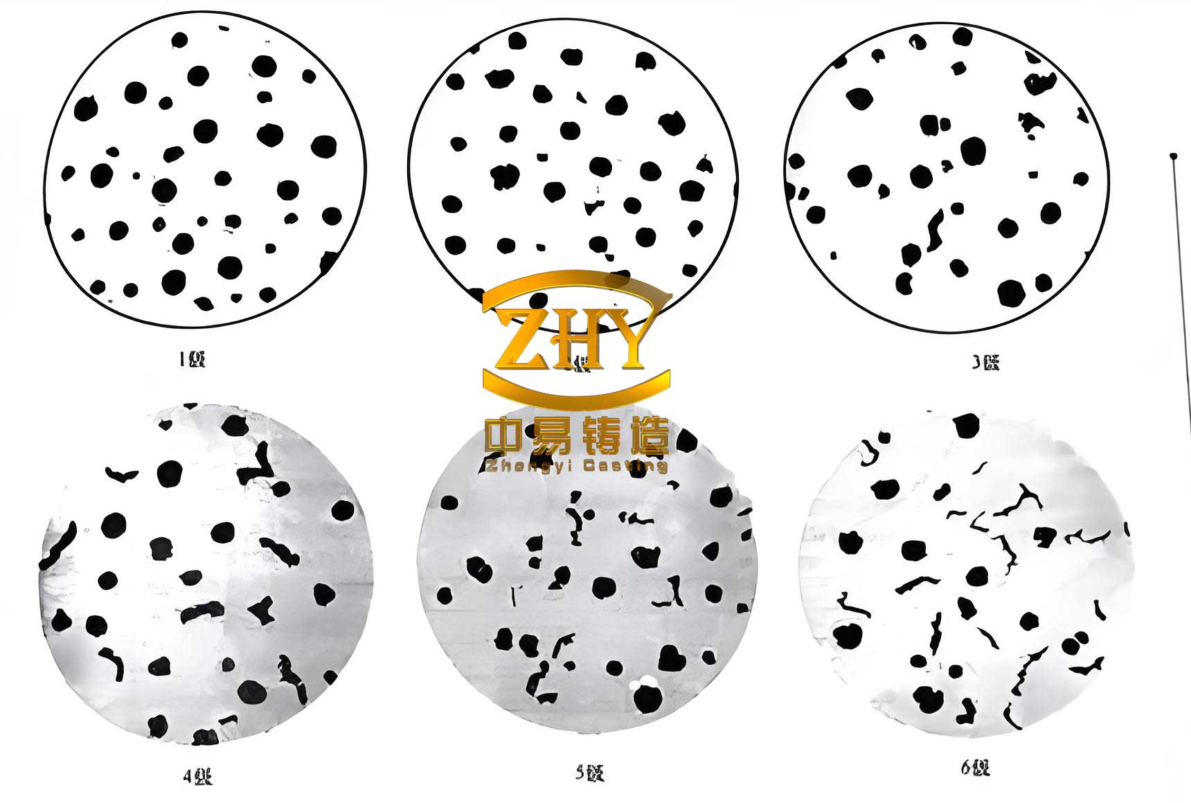
After shakeout and cooling, the casting underwent extensive evaluation. The true test of our process lay in the material’s internal structure and properties. Test coupons attached to the casting body (designed per relevant standards to represent the thermal condition of thick sections) were used for destructive analysis. Metallographic examination revealed a predominantly ferritic matrix (over 95%) with well-dispersed, spherical graphite nodules. The nodularity, quantified using image analysis software, consistently exceeded 90%. The graphite nodule count, a key indicator of inoculation effectiveness, was measured to be in the range of 100-150 nodules/mm², which is excellent for such a heavy section. This fine dispersion of graphite spheroids is directly responsible for the superior mechanical properties, as it prevents stress concentration and allows for efficient load transfer through the ferrite matrix.
The mechanical properties derived from these test coupons confirmed that the spheroidal graphite iron met the stringent QT450-10 specification, which demands a minimum tensile strength of 390 MPa, a yield strength of 260 MPa, and 10% elongation. Our results significantly surpassed these minimums. The relationship between microstructure and tensile strength in ferritic spheroidal graphite iron can be semi-empirically described by equations considering the matrix strength and the graphite phase:
$$ \sigma_{UTS} \approx \sigma_{Fe} \cdot (1 – f_g) + \beta $$
where $\sigma_{Fe}$ is the strength of the ferrite matrix, $f_g$ is the volume fraction of graphite, and $\beta$ is a strengthening term related to nodule dispersion. The high ductility is a direct consequence of the high nodularity and clean, carbide-free matrix.
| Test Category | Standard / Method | Specification Requirement | Actual Result (Average or Finding) |
|---|---|---|---|
| Tensile Strength | ASTM A536 / ISO 1083 | ≥ 390 MPa | 430 MPa |
| 0.2% Yield Strength | ASTM A536 / ISO 1083 | ≥ 260 MPa | 285 MPa |
| Elongation | ASTM A536 / ISO 1083 | ≥ 10 % | 15.5 % |
| Hardness (Brinell) | ASTM E10 | Reported for information | 165 HBW (10/3000) |
| Charpy Impact (Room Temp) | ASTM A327 | Not specified, but tested | 14 J (minimum of 3 tests) |
| Ultrasonic Testing (UT) | EN 12680-3 | 100% scanning, Acceptance Level 2 | No indications exceeding Level 2 recorded |
| Magnetic Particle Testing (MT) | EN 1369 | 100% on machined surfaces, Acceptance Level 2 | No relevant linear or clustered indications |
| Nodularity & Nodule Count | ISO 945-1 / Internal Image Analysis | ≥ 80% nodularity (client spec ≥ Grade III) | >90% nodularity, 120 nodules/mm² avg. |
| Matrix Structure | Metallographic Etching (Nital) | Predominantly Ferrite (per QT450-10) | >95% Ferrite, balance pearlite; no carbides |
The non-destructive examination was exhaustive. Full-body ultrasonic testing, conducted per EN 12680-3, involved scanning the entire casting volume with appropriate frequency probes to detect internal discontinuities like shrinkage or inclusions. The fact that all recorded indications fell within the stringent “Level 2” acceptance criteria demonstrated the effectiveness of our feeding system and the cleanliness of the melt. Magnetic particle inspection on all machined surfaces confirmed the absence of surface-breaking defects such as cracks or cold shuts. The successful passage of these tests without recourse to any weld repair—a prohibited practice for this casting—was a definitive validation of our integrated process control.
Reflecting on this production campaign, several pivotal factors converged to enable the successful manufacture of this oversize spheroidal graphite iron butterfly plate. The pre-production simulation using ProCAST was instrumental in de-risking the casting geometry, allowing us to optimize the feeding and chilling layout virtually. The selection of ultra-pure charge materials established a clean chemical baseline, which is non-negotiable for achieving consistent nodularity in heavy sections. The wire-feeding treatment method provided precise and repeatable control over the critical spheroidizing elements, magnesium and rare earths. A multi-stage inoculation strategy, culminating in late stream inoculation, was essential to maintain a high nucleation potential throughout the long solidification interval, ensuring a fine and uniform distribution of graphite spheroids. Finally, the strategic deployment of chills and high-efficiency insulating risers managed the solidification pattern, directing shrinkage into the risers and promoting a sound casting body.
This project underscores that producing premium heavy-section spheroidal graphite iron castings is a systems engineering endeavor. Every variable, from the thermodynamic design of the mold to the kinetics of metallurgical reactions in the ladle, must be understood and controlled. The excellent mechanical properties, flawless non-destructive testing results, and perfect as-cast surface integrity of the butterfly plate stand as testament to the viability of spheroidal graphite iron for the most demanding large-scale valve components. The knowledge gained, particularly in balancing composition, nucleation, and cooling for massive wall thicknesses, contributes significantly to the broader foundry industry’s capability to push the boundaries of spheroidal graphite iron applications.