
In the field of diesel engine manufacturing, the cylinder block stands as a critical component, whose casting quality directly influences engine performance. Traditionally, high-grade gray iron or alloyed iron has been the material of choice for such applications. However, in service, these materials are prone to thermal fatigue cracking, a issue intrinsically linked to the nearly zero elongation characteristic of gray iron. Moreover, the composition of high-grade gray iron often deviates from the eutectic point, resulting in a wide solidification range and poor casting properties, leading to shrinkage porosity and leakage failures. In contrast, spheroidal graphite iron exhibits superior strength and elongation under harsh conditions such as high temperature, high pressure, and poor lubrication. Ferritic spheroidal graphite iron offers better fatigue resistance compared to gray and alloyed irons, meeting the demands of complex stress, high load, and the need for both strength and toughness in diesel engine cylinder blocks. Its production cost is lower than that of alloyed iron, making it an ideal material. Therefore, this trial production focused on developing an as-cast ferritic spheroidal graphite iron cylinder block, leveraging advanced melting and casting techniques to achieve the desired microstructure and mechanical properties.
From a first-person perspective, I was involved in this project aiming to overcome the limitations of traditional materials. The goal was to produce a cylinder block with enhanced durability and performance using spheroidal graphite iron. This material, characterized by its graphite spheroids embedded in a ferritic matrix, provides a unique combination of properties. The key challenge lay in controlling the microstructure to ensure high nodularity, fine graphite size, and a predominantly ferritic matrix, all while preventing casting defects such as shrinkage and cold shuts. Through meticulous process design and execution, we achieved a successful trial run, which I will detail in this comprehensive account.
The cylinder block in question, designated C500, was a newly designed product for military applications. Its material specification required spheroidal graphite iron with a grade equivalent to QT400-18A. The casting’s external dimensions were 2,650 mm in length, 1,160 mm in width, and 870 mm in height, with a rough casting weight of 3.2 tonnes. It featured a V-type arrangement of 20 cylinder bores, with wall thicknesses ranging from a minimum of 8 mm to a maximum of 62 mm, presenting significant variations that posed challenges for uniform solidification and feeding.
| Parameter | Requirement |
|---|---|
| Chemical Composition | S ≤ 0.02%, P ≤ 0.05% |
| Impact Toughness | Average of three specimens: ≥14 J/cm², individual ≥11 J/cm² |
| Metallurgical Structure | Nodularity Grade: 1-2, Graphite Size: 5-6, Ferrite Volume Fraction: ≥90% |
| Pressure Testing | Hydraulic: 0.5 MPa for 10 min; Oil pressure: 1.2 MPa for 15 min; No leakage |
| Internal Defects | No shrinkage defects in critical areas per ultrasonic testing standards |
The melting process employed a duplex method utilizing a cupola furnace followed by a holding furnace. This approach ensures consistent temperature control and composition homogeneity. The charge composition consisted of 78% Q10 pig iron and 22% steel scrap, selected for low impurity levels to facilitate the production of high-quality spheroidal graphite iron. The target chemical composition was carefully controlled, as summarized in the following table.
| Element | Content (wt.%) |
|---|---|
| Carbon (C) | 3.51 |
| Silicon (Si) | 2.70 |
| Manganese (Mn) | 0.20 |
| Phosphorus (P) | 0.03 |
| Sulfur (S) | 0.009 |
| Magnesium (Mg) | 0.052 |
| Rare Earth (RE) | 0.041 |
The spheroidization treatment was conducted using a conventional sandwich method in a ladle. A spheroidizing agent, primarily composed of magnesium-ferrosilicon alloy, was placed at the bottom of the ladle, amounting to approximately 1.7% of the total melt weight of 4.3 tonnes. This agent facilitates the transformation of graphite from flake to spheroidal form. The reaction can be simplified as the magnesium reacting with sulfur and oxygen in the iron:
$$ \text{Mg} + \text{S} \rightarrow \text{MgS} $$
$$ \text{Mg} + \text{O} \rightarrow \text{MgO} $$
These reactions remove elements that promote graphite flake formation, allowing carbon to precipitate as spheroids during solidification. To enhance nucleation and control microstructure, inoculation was performed multiple times. Initially, 0.1% of a silicon-barium inoculant (5-15 mm granularity) covered the spheroidizing agent. As the melt was tapped, about two-thirds of the total amount, another 0.4% inoculant was added at the tap stream. After skimming, a further 0.4% inoculant was added onto the melt surface. Finally, during pouring, a stream inoculation with 0.1% fine-grained inoculant (0.2-0.7 mm) was applied. This intensified inoculation strategy is crucial for refining graphite, increasing graphite nodule count, and improving nodularity in spheroidal graphite iron. The tapping temperature from the holding furnace was maintained between 1,480°C and 1,490°C, with a pouring temperature range of 1,360°C to 1,380°C to ensure proper fluidity while minimizing gas absorption and dross formation.
The casting process was meticulously designed to address the challenges posed by the complex geometry and varying section thicknesses of the cylinder block. A three-part mold (drag, cope, and intermediate sections) was employed, facilitating the placement of cores, gating system, and feeding aids. The gating system was of a choked type, designed to ensure a smooth, non-turbulent fill. The gating ratio was set as:
$$ \Sigma F_{\text{sprue}} : \Sigma F_{\text{runner}} : \Sigma F_{\text{ingate}} = 1.18 : 1.04 : 1 $$
The system featured a stopper-controlled pouring basin. The lower ingates, consisting of 22 ceramic tubes with a diameter of 25 mm, were designed to introduce metal quietly into the mold cavity from the bottom near the cylinder walls. When approximately three-quarters of the mold was filled, the stopper was opened to allow metal to also enter through the upper ingates—16 flat gates with dimensions of 55/50 mm by 9 mm. This two-stage filling helped maintain thermal gradients favorable for feeding.
Feeding the heavy sections to prevent shrinkage defects was a paramount concern. In spheroidal graphite iron, solidification involves both liquid contraction and graphite expansion. If the expansion is insufficient or improperly timed, micro-shrinkage can occur. To counteract this, we implemented a feeding strategy using exothermic insulating risers. The efficiency of a riser can be described by its feed volume ratio. For a conventional riser, only 6-10% of its volume effectively feeds the casting. Insulating risers improve this to 20-25%, while exothermic insulating risers can achieve up to 45% efficiency. The temperature gradient maintained by such risers is critical. We placed eight large-diameter (180 mm) exothermic insulating risers equidistantly on the cope surface. The exothermic reaction generates heat, keeping the riser metal hotter longer and establishing a top-down temperature gradient, thereby enhancing the feeding pressure during the critical solidification period. The effectiveness of this approach can be related to the thermal conditions; the riser should solidify after the casting section it feeds. This can be assessed using Chvorinov’s rule for solidification time:
$$ t = k \left( \frac{V}{A} \right)^2 $$
where \( t \) is solidification time, \( V \) is volume, \( A \) is surface area, and \( k \) is a constant. By designing risers with a higher modulus \( (V/A) \) than the casting hot spots, we ensured directional solidification towards the risers. Additionally, chill plates were strategically placed in thick sections like cylinder bores and bolt holes to accelerate cooling, refine microstructure, and improve density, further preventing shrinkage defects in these critical zones of the spheroidal graphite iron casting.
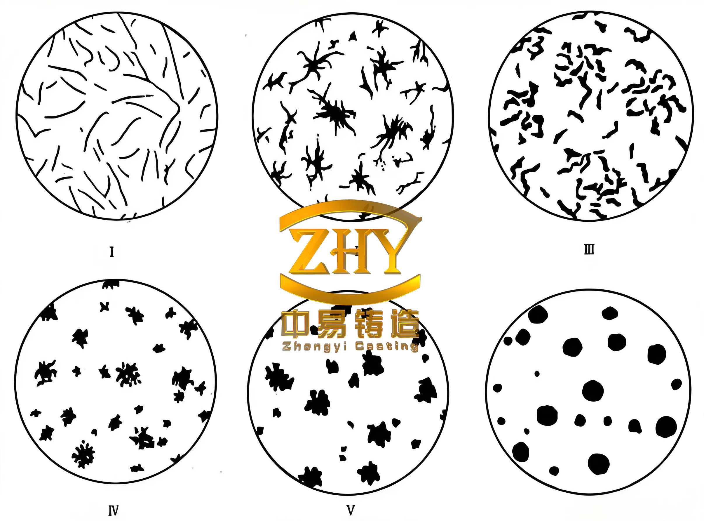
The trial production yielded castings that underwent rigorous evaluation. Specimens were extracted from the cast block for metallographic examination and mechanical testing. The microstructure of the spheroidal graphite iron was exemplary, showing well-formed graphite spheroids within a ferritic matrix. Quantitative analysis confirmed the desired characteristics. The mechanical properties met all specified requirements, demonstrating the success of the process. The results are consolidated in the tables below.
| Property | Value | Requirement |
|---|---|---|
| Tensile Strength | 442 MPa | ≥ 400 MPa |
| Yield Strength (0.2% offset) | 305 MPa | ≥ 250 MPa |
| Elongation | 22% | ≥ 18% |
| Impact Energy (Charpy V-notch) | 15 J, 15 J, 16 J | Avg. ≥ 14 J/cm² |
| Hardness (HBW) | 160 | Typically 130-180 |
| Feature | Result | Target |
|---|---|---|
| Nodularity Grade | 90% (Grade 1-2) | Grade 1-2 |
| Graphite Size | Grade 6 | Grade 5-6 |
| Ferrite Fraction | > 90% | ≥ 90% |
| Graphite Morphology | Predominantly Spheroidal | Spheroidal |
Non-destructive testing was performed to ensure internal soundness. Ultrasonic inspection of critical areas, such as cylinder bores and bolt holes, revealed defect levels compliant with industry standards for spheroidal graphite iron castings. Pressure tests, both hydraulic and oil-based, were conducted successfully with no signs of leakage, confirming the casting’s integrity and the effectiveness of the feeding system. Furthermore, a sacrificial casting was sectioned, and the examined surfaces of key regions showed no macroscopic shrinkage cavities or porosity, validating the design of the chills and risers.
The successful trial underscores several key principles in producing high-integrity spheroidal graphite iron castings. The intensified inoculation practice was instrumental in achieving a high nodule count and fine graphite. The relationship between inoculant addition and graphite nucleation can be complex, but generally, the number of graphite nodules \( N \) can be influenced by the inoculant potency and cooling rate. An empirical relation might be:
$$ N = k_I \cdot C_I \cdot \left( \frac{dT}{dt} \right)^n $$
where \( k_I \) is a constant, \( C_I \) is the inoculant concentration, \( dT/dt \) is the cooling rate, and \( n \) is an exponent. Our multiple inoculation steps ensured adequate nucleation sites throughout the melt. Furthermore, the use of exothermic insulating risers created a controlled thermal gradient, essential for feeding spheroidal graphite iron, which exhibits a pasty solidification mode. The efficiency of feeding \( \eta_f \) can be conceptualized as:
$$ \eta_f = \frac{V_{\text{feed}}}{V_{\text{riser}}} \times 100\% $$
where \( V_{\text{feed}} \) is the volume of liquid metal fed to the casting and \( V_{\text{riser}} \) is the riser volume. By employing exothermic risers, we aimed to maximize \( \eta_f \), thereby compensating for both liquid shrinkage and the limited expansion from graphite precipitation in these specific casting conditions.
In conclusion, this trial production demonstrated the feasibility of manufacturing large, complex cylinder blocks from as-cast ferritic spheroidal graphite iron. The combination of stringent chemical control, intensified inoculation, and a carefully engineered casting process with effective feeding via exothermic risers and chills resulted in a casting that met all mechanical, microstructural, and integrity specifications. The properties of spheroidal graphite iron, particularly its excellent combination of strength and ductility, make it a superior alternative to traditional gray irons for demanding applications like diesel engine cylinder blocks. Future work could focus on further optimizing the riser design using simulation software to reduce yield and on exploring the effects of different alloying elements on the high-temperature properties of spheroidal graphite iron for even more severe service conditions. The knowledge gained from this trial provides a robust foundation for the batch production of high-quality spheroidal graphite iron castings, ensuring reliability and performance in critical engine components.