
In the realm of foundry operations, the design and manufacturing of molds are pivotal for producing high-quality sand casting products. Over the years, through relentless efforts by casting process design engineers and mold practitioners, significant advancements have been made in mold quality. However, the overall independent innovation capability remains insufficient, lacking core competitiveness. From my perspective as a casting professional, this shortfall often stems from mold designers lacking specialized casting knowledge or experience, leading to designs that do not align with practical production needs. Consequently, casting enterprises frequently must undertake extensive modifications upon receiving molds. Therefore, it is imperative for casting enterprises to either cultivate their own mold design personnel or foster closer collaboration between casting process engineers and mold designers. This is a fundamental prerequisite for ensuring mold quality and a detail that must be highly prioritized in our industry.
To address these challenges, I believe that casting enterprises must invest in developing in-house expertise. While outsourcing mold design and manufacturing to suppliers can reduce immediate workload, it often introduces risks such as molds that are incompatible with casting process requirements, necessitating costly and time-consuming modifications. Critical aspects like shrinkage allowances, parting lines, template layouts, and gating systems, once set, are difficult to alter comprehensively, potentially rendering molds unusable or scrapped. Hence, we should focus on training our own mold design engineers, who can be cross-trained from casting process technicians. This approach ensures that designs are more aligned with production realities, minimizing late-stage changes and enhancing the success rate of new product development. Even if casting enterprises lack in-house mold manufacturing capabilities due to equipment and labor constraints, maintaining casting process and mold design personnel is essential for verifying process feasibility and ensuring project success.
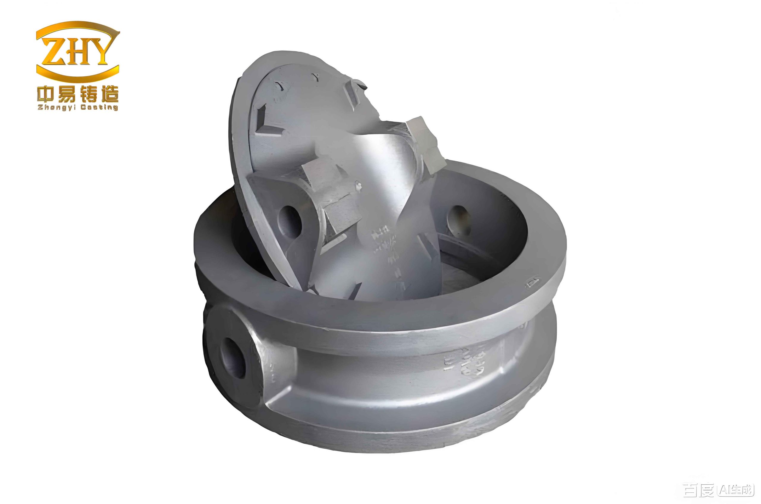
Casting process design is the cornerstone of mold design. Regardless of how superior the mold materials, surface quality, or geometric dimensions are, without a suitable casting formation process, the final sand casting products will fail to meet quality or mass-production demands. Thus, before manufacturing molds, we must thoroughly understand and optimize the casting process. Key elements include software selection, parting line determination, shrinkage allowance calculation, and gating system design. For instance, software like UG, SolidWorks, or MAGMA is commonly used, but the choice depends on familiarity and project requirements. Parting lines should be designed to minimize cores, facilitate mold operations, and ensure smooth gas venting. In sand casting, parting lines are often curved to accommodate complex geometries, and principles such as placing most of the casting in one mold half and avoiding functional surfaces are critical.
Shrinkage allowances are vital for dimensional accuracy in sand casting products. They account for thermal contraction during solidification and cooling, influenced by factors like alloy type, casting shape, and mold rigidity. For example, ductile iron typically requires allowances of 0.3% to 0.7%, while gray iron may need 0.4% to 0.9%, and non-ferrous alloys like aluminum or copper often use around 1%. The shrinkage allowance \( S \) can be expressed as a percentage of the nominal dimension \( L \):
$$ S = \alpha \cdot L $$
where \( \alpha \) is the linear shrinkage coefficient, which varies with material and process conditions. A summary table for common alloys is provided below.
| Alloy Type | Shrinkage Allowance Range (%) | Key Influencing Factors |
|---|---|---|
| Ductile Iron | 0.3 – 0.7 | Graphitization expansion, mold stiffness |
| Gray Iron | 0.4 – 0.9 | Carbon equivalent, cooling rate |
| Aluminum Alloys | 0.9 – 1.2 | Solidification range, pouring temperature |
| Copper Alloys | 1.0 – 1.5 | Thermal conductivity, mold material |
Gating system design is another critical aspect that directly impacts the quality of sand casting products. Whether open, closed, or semi-open systems are used, the goal is to achieve smooth filling, minimize turbulence, reduce gas entrapment, and ensure efficient feeding. Key considerations include minimizing flow distance, avoiding direct impingement on mold walls or cores, and designing runners and gates to promote sequential filling. The gating ratio, which relates the cross-sectional areas of sprue, runner, and gate, is often optimized using fluid dynamics principles. For laminar flow, the Bernoulli equation can be applied:
$$ P + \frac{1}{2} \rho v^2 + \rho g h = \text{constant} $$
where \( P \) is pressure, \( \rho \) is density, \( v \) is velocity, \( g \) is gravity, and \( h \) is height. In practice, we aim for a balanced gating system to prevent defects like shrinkage porosity or inclusions. For example, gates should be positioned to avoid hot spots and facilitate directional solidification toward risers. The table below outlines common gating system types and their applications in sand casting products.
| Gating System Type | Advantages | Disadvantages | Typical Use Cases |
|---|---|---|---|
| Open System | Low pressure loss, easy cleaning | High turbulence, oxidation risk | Simple, small castings |
| Closed System | Controlled flow, reduced slag | Complex design, higher cost | High-integrity castings |
| Semi-open System | Balance of flow and pressure | Requires precise calibration | Medium-complexity products |
To validate these designs, casting process simulation analysis is indispensable. Software tools like MAGMASOFT, Flow-3D, or ProCAST enable numerical modeling of filling and solidification processes, predicting defect locations such as shrinkage cavities or cold shuts. By iteratively adjusting gating and feeding systems based on simulation results, we can optimize designs before mold manufacturing, saving time and resources. For instance, simulation might reveal that modifying gate sizes by 10% reduces turbulence, enhancing the soundness of sand casting products. The general simulation workflow involves meshing the geometry, setting boundary conditions (e.g., pouring temperature, mold properties), and solving governing equations like the heat transfer equation:
$$ \frac{\partial T}{\partial t} = \alpha \nabla^2 T $$
where \( T \) is temperature, \( t \) is time, and \( \alpha \) is thermal diffusivity. This proactive approach minimizes trial-and-error in production.
Material selection for mold components is equally crucial for durability and performance. Each part—template, mold core, gating system, core box, ejector pins, and locating pins—serves distinct functions and must meet specific mechanical and thermal requirements. For templates, which connect mold cores to molding machines, cast iron is commonly used due to its strength and hardness at operating temperatures (30–70°C). Mold cores, forming the casting cavity, require high-strength, wear-resistant materials like tool steels, often embedded into templates for precision. Gating systems, subjected to abrasive sand flow, may use high-alloy cast aluminum or chrome-plated steels for lightweight and wear resistance. Core boxes, especially for hot processes, need low-carbon cast iron to resist decarburization at 210–300°C, with hardened steel shot sleeves for durability. Ejector pins and locating pins demand high hardness (e.g., 40–62 HRC) from materials like 45# steel or GCr15, treated via quenching and tempering. The table below summarizes material recommendations for key mold components in sand casting products.
| Mold Component | Recommended Material | Key Properties | Treatment/Notes |
|---|---|---|---|
| Template | Cast Iron (e.g., Grade 250) | Strength, hardness, thermal stability | As-cast or normalized |
| Mold Core | Tool Steel (e.g., H13) | High hardness, wear resistance, toughness | Heat treated to 45-50 HRC |
| Gating System | Cast Aluminum (e.g., A356) or Chrome Steel | Lightweight, abrasion resistance | Plating or anodizing for protection |
| Core Box (Hot) | Low-Carbon Cast Iron | Resistance to decarburization, heat fatigue | Shot sleeves hardened to 40-48 HRC |
| Ejector Pins | 45# Steel or A3 Steel | High surface hardness, core toughness | Quenched and tempered to 40-48 HRC |
| Locating Pins/Sleeves | GCr15 Bearing Steel | Extreme hardness, dimensional stability | Hardened to 58-62 HRC |
Furthermore, manufacturability must be considered during design. For deep cavities or fine engravings, techniques like EDM (electrical discharge machining) or layered machining may be necessary to avoid tool limitations. This foresight prevents delays and ensures that molds are feasible to produce, ultimately supporting the efficient manufacturing of sand casting products.
In conclusion, the design of casting molds—encompassing process optimization and material engineering—is fundamental to foundry success. By prioritizing in-house design capabilities, leveraging simulation tools, and selecting appropriate materials, casting enterprises can enhance mold quality, reduce post-production modifications, and improve the reliability of sand casting products. As we continue to innovate, integrating advanced technologies like AI for design automation or additive manufacturing for mold prototyping could further revolutionize this field. Ultimately, a proactive design approach not only minimizes costs but also ensures that sand casting products meet ever-evolving market demands for precision and performance.