
Casting stands as one of humanity’s earliest mastered metal hot-working techniques and remains the most widely applied liquid metal forming process. Its fundamental principle involves pouring molten metal into a pre-formed mold cavity, allowing it to cool and solidify to obtain a part or blank of a specific shape. In modern mechanical manufacturing, the foundry industry is a vital component, with its development level signifying a nation’s production strength. Its status is irreplaceable, both in developing and developed nations. The automotive industry is the largest consumer of castings, serving as the primary driving force for the advancement of foundry technologies. Within a typical automobile, the mass of cast components accounts for approximately 20% of its total weight, second only to steel, making high-quality sand casting products crucial for vehicle manufacturing.
The engine is the most critical component of an automobile, determining the vehicle’s overall lifespan and performance. Foundational and major engine components such as cylinder blocks, cylinder heads, intake manifolds, exhaust manifolds, crankshafts, and exhaust connectors are predominantly produced through casting processes. Consequently, the development trajectory of the automotive industry profoundly influences the closely linked foundry sector. As an industry primarily serving automotive needs, automotive foundries face continuous new challenges regarding casting materials and processes due to evolving automotive requirements. This context underscores the paramount importance of casting production for automotive parts.
My research focuses on a turbocharger rear exhaust connector produced by a manufacturing enterprise. This connector serves as the linking pipe between the turbocharger and the muffler in an exhaust system. During vehicle operation, it must withstand the hot exhaust gases produced by the combustion of the air-fuel mixture within the cylinders. Therefore, it necessitates properties such as vibration resistance, wear resistance, heat resistance, and gas tightness. This particular component is produced using sand casting, a testament to the versatility and capability of this method in creating complex, performance-critical sand casting products.
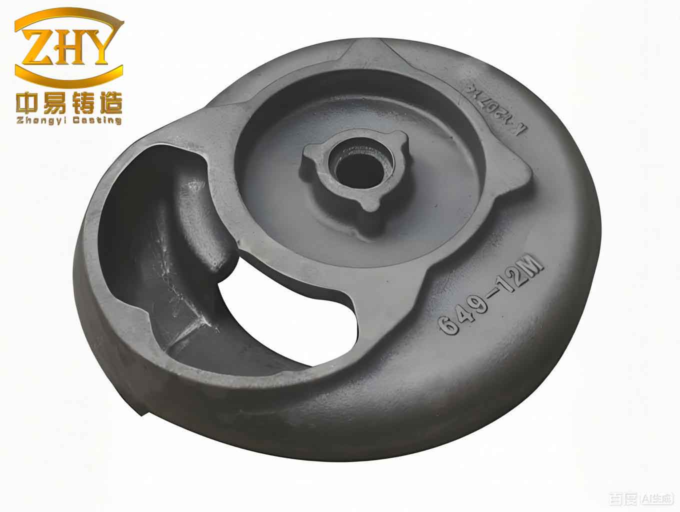
An Overview of Sand Casting
Sand casting is a manufacturing process where a mold is formed using a mixture of sand and a binder. Liquid metal is poured into this mold under gravitational force to produce a casting. The mold, or “sand mold,” is typically comprised of a cope and drag assembly, often incorporating sand cores to define internal geometries. The two most fundamental raw materials in this process are foundry sand (usually silica-based) and a mold sand binder. The advantages of sand casting are numerous: the molding materials are inexpensive and readily available, the mold-making process is relatively straightforward, and its adaptability is exceptionally broad, suitable for everything from one-off prototypes to high-volume production. This combination of adaptability, low cost, and short lead times makes it the most traditional and persistently relevant casting method for a vast array of sand casting products.
The general process flow for sand casting can be summarized in the following sequence:
- Pattern Making
- Mold & Core Making
- Mold Assembly (including core placement)
- Melting and Pouring
- Cooling and Solidification
- Shakeout and Cleaning
- Finishing and Inspection
For this specific project, a green sand mold is employed. This type of mold uses moist clay (typically bentonite) mixed with water as the primary binder for the silica sand. The mold is assembled and poured while still in its damp, “green” state, which simplifies the process for certain applications.
Gating System Design for the Exhaust Connector
The design of the gating system—the network of channels that delivers molten metal from the pouring basin to the mold cavity—is critical for casting quality. The cross-sectional area of these channels has a direct impact. If the area is too small, the pouring time becomes excessively long, risking defects like misruns (incomplete filling), cold shuts (poor fusion of metal streams), and sand inclusions. Conversely, if the area is too large, the excessively fast flow velocity can cause mold erosion (washing) and lead to slag inclusions. Therefore, determining an optimal gating system area is essential to ensure the mold fills at an appropriate, controlled rate for high-integrity sand casting products.
Selection of Gating System Type
Based on the geometry of the turbocharger rear exhaust connector, a partially pressurized (also known as a “choke at the gate” or intermediate injection) gating system is deemed most suitable. In this design, the cross-sectional area of the sprue (vertical channel) is larger than the total area of the ingates (channels entering the cavity). This creates a slight back-pressure, resulting in a slower filling velocity compared to a fully pressurized system. It offers improved slag-trapping capability in the larger cross-section runners and promotes more tranquil mold filling. This type is widely adopted for small-to-medium gray iron castings, aligning perfectly with the requirements for this particular sand casting product.
Design Calculations for the Gating System
The pouring time, indicative of the pouring rate, significantly influences final casting quality. An ideal pouring speed exists for any given casting, corresponding to an optimal pouring time \( t \) (in seconds). For gray iron castings weighing less than 450 kg with complex, thin-walled geometries, an empirical formula is commonly used:
$$ t = S_1 \sqrt{G_L} $$
where \( G_L \) is the total weight of metal poured, including the casting and the gating/risering system (in kg), and \( S_1 \) is a coefficient dependent on the main wall thickness of the casting.
The casting in question is a small, complex thin-walled iron part. From standard foundry data, the coefficient \( S_1 \) for a wall thickness in the range of 2.5-3.5 mm is 1.63. Assuming a total poured weight \( G_L \) of 6.5 kg, the calculated pouring time is:
$$ t = 1.63 \times \sqrt{6.5} \approx 4.2 \text{ seconds} $$
The effective (or average) metallostatic pressure head \( H_p \) must also be determined to calculate ingate sizes. For a top-gated or intermediate-gated system, the formula is:
$$ H_p = H_0 – \frac{h_c}{8} $$
where \( H_0 \) is the height from the top of the pouring cup to the parting line, and \( h_c \) is the total height of the casting in the mold. Assuming \( H_0 = 620 \) mm and \( h_c = 336 \) mm:
$$ H_p = 620 – \frac{336}{8} = 620 – 42 = 578 \text{ mm} $$
The minimum total cross-sectional area required for the ingates \( A_g \) (in cm²) for gray iron can be estimated using another standard formula:
$$ A_g = \frac{G_L}{0.31 \mu t \sqrt{H_p}} $$
Here, \( \mu \) is the flow loss coefficient for the gating system, which depends on mold resistance. For green sand molds with intermediate resistance, a typical value is \( \mu = 0.42 \). Substituting the known values (\( G_L = 6.5 \) kg, \( t = 4.2 \) s, \( H_p = 57.8 \) cm):
$$ A_g = \frac{6.5}{0.31 \times 0.42 \times 4.2 \times \sqrt{57.8}} \approx \frac{6.5}{0.31 \times 0.42 \times 4.2 \times 7.6} \approx \frac{6.5}{4.15} \approx 1.56 \text{ cm}^2 = 156 \text{ mm}^2 $$
For a partially pressurized system in small castings, common area ratios are applied. The sprue base/runner area is typically 1.1-1.5 times the total ingate area, and the sprue top area is 1.5-2.0 times the ingate area. For this design, the following ratios were selected:
– Sprue exit/runner area \( A_{ru} = 1.4 \times A_g \)
– Sprue top area \( A_s = 1.15 \times A_g \) (reflecting a tapered sprue)
Thus:
$$ A_{ru} = 1.4 \times 156 \text{ mm}^2 = 218.4 \text{ mm}^2 $$
$$ A_s = 1.15 \times 156 \text{ mm}^2 = 179.4 \text{ mm}^2 $$
To accommodate the specific geometry of the exhaust connector pattern and ensure smooth metal flow, the final designed areas were slightly adjusted: Ingates total \( 178 \text{ mm}^2 \), Runner \( 375 \text{ mm}^2 \), and Sprue top \( 314 \text{ mm}^2 \). These dimensions ensure proper flow characteristics for producing sound sand casting products.
| Parameter | Symbol | Value | Unit |
|---|---|---|---|
| Total Poured Weight | \( G_L \) | 6.5 | kg |
| Wall Thickness Coefficient | \( S_1 \) | 1.63 | – |
| Calculated Pouring Time | \( t \) | 4.2 | s |
| Effective Pressure Head | \( H_p \) | 578 | mm |
| Flow Loss Coefficient | \( \mu \) | 0.42 | – |
| Min. Ingate Area (Calc.) | \( A_g \) | 156 | mm² |
| Final Ingate Area (Design) | – | 178 | mm² |
| Final Runner Area (Design) | – | 375 | mm² |
| Final Sprue Area (Design) | – | 314 | mm² |
Riser and Chill Design for Soundness
To enhance directional solidification and feed metal to sections prone to shrinkage, the strategic placement of risers (feeders) and chills is paramount. For the exhaust connector, potential failure modes like gas leakage are primarily linked to shrinkage porosity, while breakage can stem from both misruns and severe shrinkage cavities. Effective riser and chill design is therefore critical for the structural integrity of such sand casting products.
Riser Design Principles
A riser is a reservoir of molten metal connected to the casting. Its purpose is to feed liquid metal to the casting during solidification to compensate for volumetric shrinkage, thereby preventing the formation of shrinkage cavities and porosity. It can also serve as a vent for gases and a trap for non-metallic inclusions. The shape of the riser influences its efficiency; a shape with a low surface-area-to-volume ratio (like a cylinder or sphere) cools more slowly, remaining liquid longer to provide feed metal. For this gray iron connector, based on its geometry and common practice, cylindrical risers were selected.
Risers must be placed in regions that are thermally “last-to-freeze,” typically the thickest sections or hotspots. Numerical solidification simulation (a subsequent step in the process design) helps identify these exact locations. For this component, the top planar surface, which is both the highest and a relatively thick section, was chosen for riser placement. This aids in establishing a favorable temperature gradient. The feeding range of a riser in gray iron is generally 10 to 17 times the section thickness or hot spot diameter. With a nominal wall thickness of 5 mm, a conservative feeding distance of 50 mm was utilized in the layout.
Application of Chills
Chills are masses of high-thermal-conductivity material (like iron or copper) placed in the mold. They act as local heat sinks, dramatically increasing the cooling rate of specific casting regions. By promoting rapid solidification in targeted areas, chills can help establish desired solidification sequences and eliminate isolated hotspots that might otherwise lead to shrinkage porosity. Based on preliminary analysis and knowledge of similar castings, the lower region of the exhaust connector bend was identified as prone to micro-shrinkage (porosity). The strategic placement of iron chills in this area induces localized chilling, ensuring this section solidifies quickly and is fed by adjacent, slower-solidifying metal, thereby mitigating the defect.
| Potential Defect | Primary Cause | Mitigation Method | Design Principle Applied |
|---|---|---|---|
| Gas Leakage | Shrinkage Porosity/Cavity | Riser Placement | Provide liquid metal feed to compensate for solidification shrinkage. |
| Fracture/Breakage | Misrun, Major Shrinkage | Optimized Gating, Riser & Chill | Ensure complete fill and sound internal structure in stress-bearing areas. |
| Localized Porosity | Isolated Hot Spot | Chill Placement | Increase local cooling rate to eliminate last-to-freeze isolated pools. |
Core Design and Manufacturing
The production of complex, hollow sand casting products like an exhaust pipe inherently requires the use of cores. Cores are pre-formed sand shapes inserted into the mold to define the internal passages and cavities of the casting. For this tubular component, creating the internal bore is the core’s essential function.
Selection of Core Sand Material
The core material must withstand significant thermal and mechanical demands. During pouring, the core is rapidly enveloped by molten metal, experiencing substantial heat and buoyant forces. Therefore, core sand must exhibit high strength at both room temperature (for handling) and at elevated temperatures (to resist erosion and deformation). Among modern core-making materials, resin-bonded sands offer an excellent balance of properties. Their adoption has significantly advanced the capability to produce intricate cores. Coated sand, or “shell sand,” is one prominent type of resin sand used for cores.
Coated sand refers to silica sand grains uniformly coated with a thin layer of thermosetting resin (typically phenolic). It is a free-flowing granular material at room temperature and can be stored for extended periods. When heated in a core box, the resin melts, flows, and then cures (cross-links), forming a strong, rigid shell. This material is extensively used in the automotive industry for components like cylinder heads, intake and exhaust manifolds, and various pumps—making it an ideal choice for the exhaust connector core. Its good collapsibility after casting is also beneficial.
The Core-Making Process and Machine
For the production of the exhaust connector core, a shell core shooting machine (or coated sand core shooter) is employed. This machine automates the core-making process for high consistency, which is vital for mass-producing reliable sand casting products. The core shooter’s main subsystems include a sand reservoir and feeding mechanism, a shooting head, a heated core box assembly, an ejector mechanism, and a programmable logic controller (PLC) for precise sequence control.
The automated cycle for producing a single core involves a tightly coordinated sequence:
- Sand Loading: The sand gate opens, filling the shooting chamber with coated sand.
- Chamber Seal: The sand gate closes, sealing the chamber.
- Core Box Clamping: The two halves of the heated core box are clamped together horizontally.
- Head Engagement: The shooting head lowers to form a tight seal against the core box.
- Vent Closure: Air vents on the core box are temporarily closed.
- Shooting: Compressed air is blasted into the chamber, fluidizing and forcefully injecting the sand into all cavities of the hot core box.
- Curing: The heat from the core box (typically 220-280°C) melts and cures the resin coating, forming a solid shell. The excess, uncured sand remains in the center, forming a “back-up”.
- Vent Opening & Head Retraction: Vents are opened to release pressure, and the shooting head retracts.
- Core Box Opening: The horizontal clamp releases, and the core box opens.
- Core Ejection: Ejector pins push the finished core out of the box.
- Core Removal & Cooling: The hot core is removed and allowed to cool.
Temperature control within the core box is critical, managed by digital temperature controllers to ensure even heating and consistent cure quality across all sand casting products.
Core Quality Verification
A produced core must be validated before use in mold assembly. Checks include:
- Geometric Accuracy & Dimensional Tolerance: Verifying against the master drawing.
- Surface Finish: Inspecting for smoothness, free from cracks or breaks.
- Color Inspection: This is a crucial, rapid check for cure quality. A properly cured shell core typically exhibits a uniform yellowish-brown to brown color on its surface. An under-cured core may show pale yellow or even white areas (insufficient resin reaction), indicating low strength. An over-cured core will appear dark brown or black, suggesting degraded resin and potential brittleness. Only cores with the correct color profile and physical integrity are approved for making production molds.
| Aspect | Material/Parameter | Typical Value/Range | Purpose/Role |
|---|---|---|---|
| Core Sand Type | Phenolic Resin Coated Sand | – | Provides high strength, good collapsibility, and dimensional accuracy. |
| Core Box Temperature | Heated Core Box | 230 – 260 °C | To melt and cure the resin binder uniformly. |
| Cure Time (in box) | Dwell Time | 15 – 60 seconds | Ensures complete resin cross-linking for maximum strength. |
| Key Quality Indicator | Core Color | Uniform Yellow-Brown | Visual check for proper curing; pale=under-cured, dark=over-cured. |
Summary and Validation
Sand casting, with its straightforward mold fabrication and accessible materials, persists as a foundational manufacturing process. This detailed exploration has covered the primary design aspects for sand casting a turbocharger rear exhaust connector, focusing on the gating system, riser and chill application, and core design/manufacture. The subsequent and essential step in modern foundry practice involves virtual validation using casting simulation software.
Numerical simulation of the filling and, more importantly, the solidification process allows for the prediction of potential defects such as shrinkage porosity or cold shuts. For the exhaust connector, simulation would typically reveal isolated hotspots in the lower bend area and potentially in thicker mounting flanges. The designed riser on the top plane and the iron chills placed in the lower region are direct responses to these simulated results. Their purpose is to engineer a controlled, directional solidification pattern where the casting sections solidify sequentially toward the riser, which remains liquid longest, effectively feeding all regions and eliminating shrinkage voids.
The synergy between risers and chills is powerful. While the riser provides the liquid metal reservoir, the chill strategically accelerates cooling in specific zones, “steering” the solidification front. In this case, the combined design ensures that, under standard pouring conditions, the lower section solidifies rapidly (aided by the chill) and is fed from the still-liquid metal in the adjacent, slower-cooling areas, which are in turn fed by the riser.
The ultimate validation is physical production. Castings produced using this finalized sand casting工艺—with the calculated gating, designed riser, specified chills, and precision-coated sand cores—were inspected. The results confirmed that the casting body itself was free from defects like misruns, shrinkage cavities, or porosity. Any minor imperfections observed were confined to the gating system, which is removed during subsequent machining and does not affect the component’s functionality. Therefore, the cast connector met all quality specifications for a gas-tight, durable automotive part.
This successful outcome demonstrates the efficacy of the systematic design approach. It validates the calculated parameters, the strategic use of feeding and chilling aids, and the selection of advanced core-making technology. The process provides a reliable, manufacturable blueprint for producing this specific turbocharger rear exhaust connector, contributing to the robust supply of high-quality sand casting products for the automotive sector. The principles applied here—from fluid flow calculations and thermal management to advanced material selection—are universally applicable, underscoring the sophisticated engineering behind even the most traditional casting methods.