
The production of high-quality sand casting products remains a cornerstone of modern manufacturing, particularly for complex components. However, traditional and semi-automated foundry lines often grapple with challenges that impede efficiency and consistency. Common issues include unstable mold transportation and positioning, low recycling rates of auxiliary equipment like flasks and weights, high labor intensity, and suboptimal production space utilization. These factors collectively constrain throughput, increase operational costs, and compromise the stability of the final sand casting products. This article details the design and practical implementation of a fully automatic horizontal parting molding line engineered to address these systemic shortcomings. The core philosophy centers on achieving a high degree of automation, seamless integration of key processes, and the intelligent recycling of tooling, thereby enhancing the overall manufacturing flow for sand casting products.
The design was driven by specific performance targets for a production facility focusing on automotive components such as hubs and clutches (HT250 grade). The annual output goal was set at 12,000 tons, translating to approximately 440,000 molds per year, with a target yield exceeding 90%. The line needed to accommodate sand flasks of different dimensions (e.g., 610mm x 610mm x 280-400mm and 570mm x 670mm x 360-560mm) and integrate seamlessly into an existing workshop footprint of 140m x 24m.
System Design and Layout Philosophy
The overall layout is the foundational element dictating the smoothness of material flow for sand casting products. The designed line is structured around four parallel conveyor tracks, each serving a distinct phase of the production cycle. The first track is the pouring line, where assembled molds receive molten metal. The second track is a transition line dedicated to mold manipulation. The third and fourth tracks are extended cooling lines, allowing sand casting products to solidify completely before shakeout. This spatial separation is crucial for managing cycle times and preventing bottlenecks.
At the heart of the line are two identical horizontal parting molding machines, capable of adjustable sand mold height. They are fed by an overhead belt conveyor system connected to the sand storage and reclamation system. The core automation challenge involves coordinating the movement of mold carriers (pallets), the application and removal of flasks and weights, and the transfer of sand casting products between these tracks. The workflow is a continuous loop: Molding -> Pallet Transfer & Flask/Weight Application -> Pouring -> Cooling -> Flask/Weight Removal -> Shakeout & Casting Extraction -> Pallet Return.
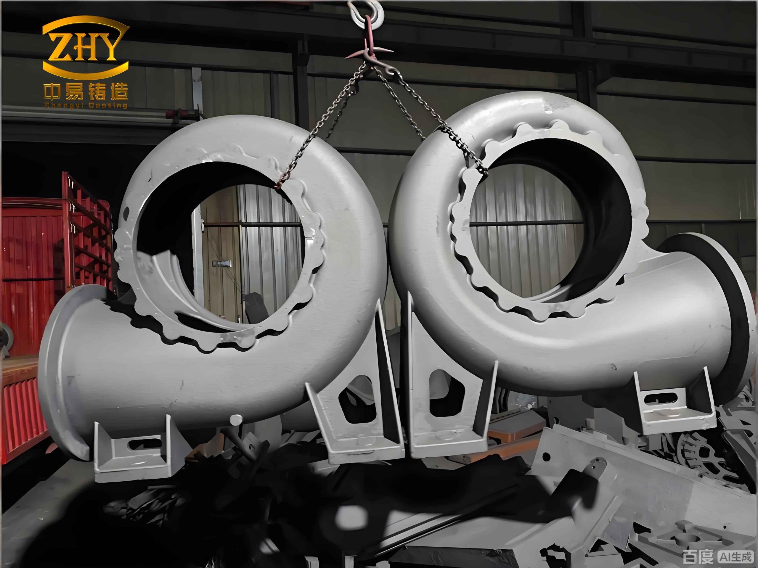
The entire process is governed by a centralized Programmable Logic Controller (PLC) system, which synchronizes all mechanical actions based on sensor inputs. The key operational steps are systematically executed:
- The molding machine signals for sand supply and completes the molding cycle.
- The finished mold is pushed onto the first conveyor track.
- A pallet clamping and positioning mechanism secures the pallet at various workstations.
- A flask and weight transfer device picks up reusable flasks and weights from the cooling line and places them onto the new mold on the pouring line.
- Pallet transfer devices index the loaded mold to the pouring station for automated pouring.
- After pouring, the mold is transferred to the long cooling lines.
- Once cooled, the same flask/weight transfer device removes the flasks and weights, returning them to the start of the cycle.
- The exposed sand mold is then pushed into a vibrating conveyor for shakeout, where the finished sand casting product is separated from the sand.
- Empty pallets are circulated back to the molding machines, and reclaimed sand is transported via an underground belt system for re-processing.
Design of Critical Mechanical Subsystems
The reliability and precision of the line hinge on several custom-designed mechanical subsystems. Each addresses a specific weakness in conventional setups for producing sand casting products.
1. Flask and Weight Transfer Device
This device is central to achieving tooling recycling. It is a gantry-style unit equipped with independent lifting mechanisms for the flask and the weight. Each mechanism uses a cylinder for vertical movement and a pneumatically actuated brake/clamp to grip the tooling. The entire gantry traverses between the pouring line (Track 1) and the transition line (Track 2) on a motor-driven roller chain. Precision is ensured by locator pins on the device that engage with corresponding holes on the flask frames. The system’s function can be summarized by its engagement sequence:
- Positioning over the target flask/weight on Track 2.
- Descending and clamping.
- Lifting and traversing to Track 1.
- Descending and releasing onto a new mold.
This automation eliminates manual handling, ensures consistent placement to prevent mold shift (misrun), and significantly accelerates the cycle.
2. Pallet Clamping and Positioning Mechanism
To prevent movement during critical operations like flask placement, pouring, and transfer, a robust clamping system is employed at key stations. The mechanism uses a single driving cylinder connected to a linkage and gear system. The cylinder action rotates two parallel shafts in opposite directions. Clamping arms attached to these shafts then simultaneously engage the sides of the pallet, locking it firmly in place. The use of gears ensures synchronized movement and equal clamping force on both sides, which is vital for the dimensional accuracy of the subsequent sand casting products. The clamping force $F_c$ can be related to the cylinder force $F_{cyl}$ and the linkage geometry:
$$F_c = \eta \cdot F_{cyl} \cdot \frac{L_{arm}}{r_{gear}}$$
where $\eta$ is the mechanical efficiency, $L_{arm}$ is the effective length of the clamping arm, and $r_{gear}$ is the pitch radius of the driving gear.
3. Pallet Transfer and Indexing Devices
Moving pallets between perpendicular conveyor tracks is achieved through dedicated transfer cars. These devices feature a sliding frame that aligns with different tracks. A motor-driven chain pushes the pallet onto the transfer car. The car then moves laterally on rails to align with the target track, where a small cylinder ejects the pallet. Limit switches, dampers, and sensors ensure precise start and stop positions, preventing impacts that could damage the fragile sand molds containing the sand casting products. The transfer time $t_{transfer}$ is a critical component of the overall cycle time $T_{cycle}$:
$$T_{cycle} = t_{mold} + t_{transfer} + t_{pour} + t_{cool} + t_{shakeout}$$
Optimizing $t_{transfer}$ through rapid yet controlled motion of the transfer car is essential for high throughput.
4. Sand Mold Push-Out and Shakeout System
After flask removal, the sand mold must be fed into the shakeout system. A dedicated push-out mechanism, typically a chain-driven platen, gently but firmly pushes the mold off its pallet and onto a vibrating grid conveyor. The vibratory action breaks down the sand mold, separating the solidified sand casting product from the expendable sand. The sand falls through the grid for reclamation, while the casting is conveyed away for cleaning and finishing.
| Subsystem | Primary Function | Key Components | Control Method |
|---|---|---|---|
| Flask/Weight Transfer | Tooling recycling & placement | Gantry, Lift Cylinders, Clamp Brakes, Servo Motor | PLC via position sensors |
| Pallet Clamp | Secure positioning during operations | Driving Cylinder, Linkage, Gear Pair, Clamping Arms | PLC via proximity sensors |
| Pallet Transfer Device | Inter-track mold transportation | Transfer Car, Drive Motor, Eject Cylinder, Rails | PLC via limit switches & encoders |
| Mold Push-Out | Transfer mold to shakeout | Chain Drive, Push Plate, Guide Rails | PLC sequenced with shakeout |
| Sand Reclamation | Return used sand for processing | Underground Belt Conveyors, Bucket Elevator | Continuous run with level monitoring |
Integrated Control System Architecture
The seamless operation of the entire line for manufacturing sand casting products is orchestrated by a hierarchical control system built around a master PLC (e.g., Mitsubishi FX5U series). This system integrates discrete control, motion control, and human-machine interface (HMI) functions.
Control Hierarchy and Communication
The master PLC acts as the central brain. It communicates with the two molding machines via a dedicated network (e.g., N:N network over RS-485). Remote I/O stations, located near clusters of actuators and sensors, are connected using a fieldbus system (e.g., CC-Link). This distributed I/O architecture significantly reduces wiring complexity. The HMI touchscreen provides operators with system status, production data, and manual override capabilities. All critical devices—servo drives for precise movement, solenoid valves for hydraulic and pneumatic circuits, and motor starters—are commanded by the PLC’s output modules.
Sequential Logic and Interlocking
The production process is broken down into a precise sequence of steps, each triggered by the completion of the prior step. For instance, the “Flask Transfer” command is only issued after receiving confirmation signals that “Mold Push-Out is Complete” AND “Pallet is Clamped at Station X.” This interlocking is vital for safety and preventing mechanical collisions. The molding machine’s internal sequence (close mold, shoot sand, compact, open mold, etc.) is also controlled by its local PLC in tight coordination with the master. The core control logic can be visualized as a state machine where the system progresses from one defined state $S_n$ to the next $S_{n+1}$ based on a set of input conditions $C$:
$$S_{n+1} = f(S_n, C) \quad \text{where } C = \{I_1, I_2, …, I_k\}$$
Here, $I_k$ represents inputs from sensors like limit switches, position sensors, and pressure transducers.
| Input (I) Address | Device/Sensor | Output (O) Address | Actuator/Device |
|---|---|---|---|
| I0.0 | Mold-in-Position at Station A | Q0.0 | Activate Station A Clamp |
| I0.1 | Clamp Closed Confirmation | Q0.1 | Start Flask Transfer Cycle |
| I0.2 | Flask Transfer Home Position | Q0.2 | Extend Flask Lift Cylinder |
| I0.3 | Flask Gripped Sensor | Q0.3 | Engage Flask Grip Brake |
| I0.4 | Pouring Complete Signal | Q0.4 | Start Pallet Transfer to Cooling Line |
| I0.5 | Cooling Time Elapsed | Q0.5 | Activate Mold Push-Out |
Hydraulic and Pneumatic Control
The molding machines and large actuators primarily use hydraulic power for high-force operations like compaction. The hydraulic system is composed of multiple independent circuits (e.g., for upper/lower mold plate movement, pattern draw, mold push) controlled by directional control valves actuated by the PLC. Pneumatic systems are used for faster, lower-force actions such as activating clamps, brakes, and some gating valves. The PLC controls solenoid valves to direct air flow, enabling rapid and reliable sequencing essential for the high-speed production of sand casting products.
Operational Analysis and Performance Metrics
The implementation of this fully automatic horizontal parting line has yielded transformative results in the production of sand casting products. A comparative analysis against the previous semi-automated, labor-intensive method highlights the improvements.
Quantitative Performance Gains
The primary metrics revolve around labor efficiency, space utilization, yield, and output. The automated line operates for 16 hours per day with only 2 workers per shift for monitoring and minor intervention, compared to 32 workers required for the previous method to achieve a lower output. This represents a labor reduction of over 90% for the core molding-to-shakeout processes. The streamlined layout and vertical integration of processes also reduced the production area footprint by approximately 22%. Most importantly, the consistent, automated handling and positioning have increased the casting qualification rate to approximately 99.4%, significantly reducing waste and rework costs associated with defective sand casting products.
The overall equipment effectiveness (OEE) for the line can be conceptually modeled, showing improvement. While actual calculation requires specific availability, performance, and quality data, the factors are enhanced:
$$OEE = Availability \times Performance \times Quality$$
* Availability increases due to reduced manual stoppages and faster tooling changeovers.
* Performance increases as the automated cycle time is faster and more consistent than manual cycles.
* Quality increases directly due to the higher qualification rate.
| Performance Metric | Previous Semi-Automatic Method | New Fully Automatic Line | Improvement |
|---|---|---|---|
| Labor per shift (core line) | 16 workers | 2 workers | -87.5% |
| Daily Output (equivalent units) | ~28.8 units* | ~46.4 units* | +61.1% |
| Production Area Utilization | Baseline (100%) | ~77.9% of baseline | Space freed up (~22.1%) |
| Casting Qualification Rate | ~90-92% (estimated) | ~99.4% | Significant reduction in scrap |
| Operational Environment | High dust, manual handling | Contained sand recycling, automated handling | Markedly improved |
| * Unit scale normalized for comparison; actual figures are molds per day for specific sand casting products. | |||
Qualitative and Strategic Benefits
Beyond the numbers, the line delivers substantial qualitative benefits. The work environment is cleaner and safer due to enclosed sand recycling and the elimination of heavy manual labor. The consistency of automation ensures that every mold for sand casting products is handled identically, leading to more predictable and uniform product quality. The flexible design, with adjustable mold heights and programmable logic, allows for quicker changeovers between different types of sand casting products, enhancing the foundry’s market responsiveness.
The economic benefit extends beyond labor savings. The reduction in scrap directly saves material and energy costs. The efficient recycling of flasks, weights, and sand reduces consumable expenses. The high throughput maximizes the return on capital investment. The total cost of ownership $C_{total}$ for producing a batch of sand casting products is favorably impacted:
$$C_{total} = C_{capital} + C_{labor} + C_{material} + C_{energy} + C_{scrap}$$
The automated line increases $C_{capital}$ but dramatically reduces $C_{labor}$, $C_{material}$ (via less scrap), and $C_{energy}$ per unit, leading to a lower $C_{total}$ at scale.
Conclusion
The design and successful application of this fully automatic horizontal parting molding line demonstrate a comprehensive solution to the endemic inefficiencies in traditional sand casting production. By integrating customized mechanical subsystems—such as the automated flask/weight transfer device, precision clamping mechanisms, and coordinated pallet handling—with a robust, PLC-centralized control system, the line achieves a remarkable degree of synchronization and reliability. The results confirm that such automation is not merely about replacing manual labor but about re-engineering the entire process flow for manufacturing sand casting products. The outcomes include a drastic increase in productivity and yield, a significant reduction in operational costs and floor space, and the creation of a superior working environment. This system provides a scalable and effective model for small and medium-sized foundries aiming to modernize their operations and enhance their competitiveness in the production of high-quality sand casting products. The principles of modular design, tooling recycling, and integrated control are broadly applicable for advancing automation in discrete manufacturing processes.