
This article delves into a detailed, first-person technical exploration of the manufacturing process for a high-integrity, semi-enclosed shell component using Al-Cu alloy via the sand casting method. The focus is on overcoming the challenges associated with complex geometries and stringent aerospace-grade specifications. The successful production of such sand casting products validates the viability of this process for critical structural applications.
Aluminum alloys, as one of the lighter metallic structural materials, are pivotal in advanced engineering sectors. Among them, Al-Cu alloys stand out for their superior combination of high strength, good toughness, and excellent castability, making them a prime candidate for demanding sand casting products. The inherent flexibility and cost-effectiveness of sand casting provide an ideal manufacturing pathway for complex, low-to-medium volume components where performance cannot be compromised.
1. Component Analysis and Technical Requirements
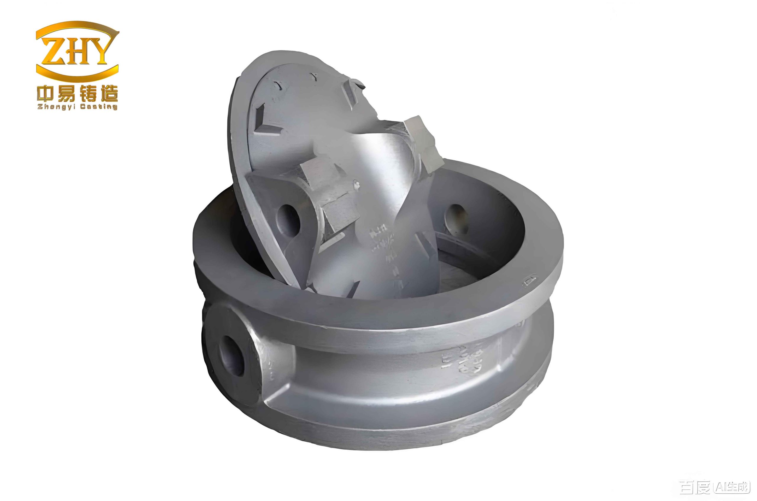
The subject component is a semi-enclosed shell characterized by a substantial cover plate (39 mm thick), a cylindrical body with a rectangular cross-section (690 mm in height), and a nominal wall thickness of 12 mm. A critical constraint is that the internal surfaces are designated as non-machined, placing a premium on the dimensional accuracy and surface integrity achieved directly from the mold. This necessitates a casting process capable of delivering net-shape or near-net-shape sand casting products. The technical mandates are severe: no welding repairs or hot deformation correction is permitted. The mechanical properties must exceed a room-temperature tensile strength of 320 MPa, yield strength of 230 MPa, and elongation of 3%. Furthermore, dimensional stability is crucial, with allowable wall thickness variation limited to ±0.4 mm, and machined surfaces must be free from shrinkage porosity, cavities, sand inclusion, and slag defects.
2. Foundry Process Design
The design of the foundry process is the cornerstone for achieving high-quality sand casting products. Every element is interlinked to control metal flow, heat transfer, and solidification.
2.1 Determination of Pouring Method: Counter-Pressure Casting
To meet the exacting internal quality standards, counter-pressure casting (also known as differential pressure casting) was selected. This method involves pressurizing the mold cavity with an inert gas before and during pouring. The key advantages for producing premium sand casting products are:
- Controlled Filling: The back-pressure in the cavity prevents turbulent entry, jetting, and splashing of the molten metal. This results in a laminar, quiescent fill, drastically reducing oxide film formation and gas entrapment.
- Enhanced Feeding: The elevated pressure is maintained throughout solidification. This pressure acts on the mushy zone, effectively suppressing the formation of micro-shrinkage (micropores) and promoting a denser, more homogeneous grain structure. The solubility of gases in the solidifying metal is also increased under pressure, minimizing hydrogen-induced porosity.
2.2 Gating System Design: Vertical Slot Gating
The component’s geometry dictates a bottom-fed, vertical slot gating system. This orientation positions the thick cover plate and end frames horizontally, which is optimal for controlled filling and establishing a favorable thermal gradient for directional solidification. The design principles for such a system are guided by empirical relationships. The number of vertical sprue sleeves (or slots, *n*) required can be initially estimated based on the component’s perimeter (*S*) and wall thickness (*δ*):
$$ n = k \cdot \frac{S}{δ} $$
where the empirical coefficient *k* typically ranges from 0.016 to 0.028 for alloys like Al-Cu under controlled filling conditions. For the subject shell with a large perimeter, the calculated number was high. However, the final design must also consider the effective feeding range of each slot and the location of thick sections. Consequently, eight equally spaced vertical slot gates were designed around the cylindrical body. The dimensions of an individual slot—its thickness (*a*), width (*b*), and the corresponding sprue diameter (*D*)—are interrelated:
$$ a = (0.8 \sim 1.5)δ $$
$$ b ≈ \frac{1}{2}D + (15 \sim 35)\text{ mm} $$
$$ D = (4 \sim 6)a $$
These relationships ensure the slot acts as an effective choke to regulate flow velocity and provides adequate cross-sectional area for feeding during solidification. A significant riser was added atop the thick cover plate to act as a concentrated feed metal reservoir, compensating for the substantial volumetric shrinkage in that region.
2.3 Application of Chills and Riser Optimization
To enforce a strong directional solidification sequence from the extremities of the casting back toward the feeders (slots and riser), external chills were strategically placed. Chill design is critical for manipulating the solidification morphology in sand casting products.
- Inter-slot Chills: Placed between adjacent vertical slot gates on the cylindrical wall, these chills rapidly extract heat, creating a steep temperature gradient that encourages solidification fronts to progress from the chill toward the warmer slot gate.
- Cover Plate Chill: Positioned beneath the thick cover plate, this chill accelerates cooling at the bottom of this heavy section, helping to shift the thermal center upward toward the riser, thereby making the riser more effective.
The combined effect of the chills and the gating system is to create a thermal hierarchy, ensuring the last areas to solidify are the slots and the riser, which are full of liquid metal ready to feed shrinkage.
| Process Element | Design Principle / Formula | Purpose in Sand Casting Products |
|---|---|---|
| Number of Slot Gates (n) | $$ n = k \cdot \frac{S}{δ}; k=0.016-0.028 $$ | To ensure uniform metal distribution and adequate feeding coverage for the entire component perimeter. |
| Slot Thickness (a) | $$ a = (0.8 \sim 1.5)δ $$ | To regulate flow rate; too thin causes premature freezing, too thick reduces flow control. |
| Sprue Diameter (D) | $$ D = (4 \sim 6)a $$ | To provide sufficient metal head pressure and volume to feed through the slot during solidification. |
| Chill Placement | Empirical, based on thermal simulation. | To create localized rapid cooling, enforce directional solidification, and eliminate isolated hot spots. |
3. Numerical Simulation and Solidification Analysis
Prior to physical prototyping, the designed process was rigorously analyzed using Novacast simulation software. This step is indispensable for optimizing the manufacturing of complex sand casting products, as it allows for virtual testing and refinement without material waste.
The simulation model incorporated the 3D geometry of the part, the gating system, riser, chills, and the sand mold properties. The initial pouring temperature was set at 680 ±5°C. The filling simulation confirmed a quiescent, bottom-up fill without any predicted misruns or cold shuts. The most critical output was the solidification analysis. The temperature gradient plots clearly demonstrated the efficacy of the chills. Regions adjacent to the chills solidified first, with solidification fronts progressing smoothly toward the slot gates and the top riser. The riser remained liquid longest, confirming its role as an effective feeder. The simulation’s porosity prediction module indicated areas of potential micro-shrinkage in junctions, but no major macro-shrinkage cavities were forecasted, validating the fundamental soundness of the feeding system design. This virtual verification provided high confidence to proceed to tooling and casting.
| Simulation Phase | Key Observations & Results | Implication for Final Sand Casting Products |
|---|---|---|
| Filling (0-65s) | Smooth, laminar fill front progression from bottom gates. No visible turbulence or air entrapment. | Predicts clean, oxide-free internal surfaces and reduced gas porosity. |
| Solidification (Up to 182s) | Clear directional solidification from chills/component ends toward slot gates and riser. Riser is thermal “hot spot”. | Confirms feeding path effectiveness, minimizing shrinkage defects in the main casting body. |
| Porosity Prediction | Scattered areas of low-density (micro-shrinkage) predicted at some thermal centers; no major cavities. | Indicates acceptable internal quality likely meeting Class I radiographic standards; focus for potential future optimization. |
4. Pattern and Mold Manufacturing
The production of accurate and durable patterns is essential for replicating the desired geometry in sand casting products. For this project, a metal (cast steel) master pattern was constructed. The pattern design must account not only for the part geometry but also for fundamental foundry allowances:
- Shrinkage Allowance: An appropriate linear contraction factor (specific to the Al-Cu alloy) was applied to all part dimensions.
- Machining Allowance: An additional 5 mm of material was added to all surfaces designated for post-casting machining.
- Draft Angles: A uniform draft of 2° was applied to all vertical faces to facilitate pattern withdrawal from the sand mold without drag.
- Fillet Radii: Unspecified corners were given generous fillets (R5-R8 mm) to reduce stress concentration and improve metal flow during filling.
The complex, semi-enclosed nature of the shell necessitated a split-pattern design. The parting line was strategically placed at the base of the thick cover plate. Using CAD software (like UG NX), the complete mold assembly was decomposed into core boxes for producing the upper and lower sand cores, and the main drag and cope patterns. This modular approach allows for the creation of the intricate internal cavity of the shell.
5. Sand Mold Production and Preparation
The mold was produced using a resin-bonded sand system. The process followed these critical steps:
- Molding: The prepared pattern was placed in a molding flask, and resin-coated sand was blown or rammed around it to form the mold halves and cores with high uniformity and compaction.
- Curing: The assembled sand molds were left to air-cure for approximately 50 hours, allowing the chemical binder to achieve initial strength.
- Thermal Reinforcement: To significantly enhance the mold’s strength and rigidity—vital for withstanding the metallostatic and counter pressures without distortion—the cured molds underwent a low-temperature bake at 500°C for 4-5 hours. This step drives off residual moisture and fully cures the resin, resulting in a hard, dimensionally stable mold.
- Coating: The mold cavity surfaces were coated with a refractory wash. This coating improves surface finish, prevents metal penetration into the sand grains, and facilitates easier shakeout of the final sand casting products.
- Mold Assembly: The baked and coated cores and mold halves were meticulously assembled, ensuring proper alignment and sealing to prevent run-outs during pouring.
6. Melting, Pouring, and Post-Processing
The charge material consisted of certified Al-Cu alloy ingots. Melting was conducted in the furnace chamber of the counter-pressure casting unit under a protective atmosphere to minimize hydrogen pickup and oxidation. After degassing and slag removal, the temperature was stabilized at the target 680°C. The entire pouring sequence was then executed under the controlled differential pressure cycle, ensuring the simulated filling conditions were replicated in practice. After solidification and cooling, the casting was shaken out, and the gating system and riser were removed. The casting subsequently underwent a T6 heat treatment cycle (solution heat treatment, quenching, and artificial aging) to achieve the peak strength properties specified for the alloy.
7. Results and Quality Validation
The final sand casting product underwent a battery of inspections to validate the success of the developed process.
7.1 Internal Soundness
Visual inspection after shot blasting revealed a clean, smooth surface free from major defects. Non-destructive testing (NDT) was critical:
- Radiographic Testing (X-ray): The casting was examined for internal discontinuities such as shrinkage cavities, porosity, and inclusions. The results confirmed the absence of major defects, with internal soundness compliant with the stringent Class I requirements of aerospace standards like HB 963-2005.
- Fluorescent Penetrant Inspection (FPI): This surface NDT method verified that the casting was free from surface-breaking cracks or fine porosity.
7.2 Mechanical Properties
Separately cast test coupons (from the same melt and heat treatment lot) were machined into standard tensile specimens. The results, as tabulated below, conclusively met and exceeded all specified mechanical property thresholds, demonstrating that the process yields sand casting products with excellent structural integrity.
| Sample ID | Tensile Strength (MPa) | Yield Strength (MPa) | Elongation (%) |
|---|---|---|---|
| 1 | 325 | 235 | 3.4 |
| 2 | 331 | 240 | 3.1 |
| 3 | 327 | 237 | 3.5 |
| 4 | 332 | 243 | 4.1 |
| 5 | 326 | 231 | 3.1 |
| 6 | 321 | 239 | 3.9 |
| Specification | ≥320 | ≥230 | ≥3 |
7.3 Dimensional Accuracy
A 3D optical scan of the cast component was compared against the nominal CAD model. The analysis showed that over 90% of the measured dimensions fell within the CT9 grade tolerances as per ISO 8062 (GB/T 6414). This is a commendable achievement for a large, complex sand casting product, directly attributable to the stable mold process (baked resin sand) and controlled solidification. The minor deviations observed were attributed to non-uniform shrinkage in complex geometric regions and minute assembly tolerances in the mold stack-up. Crucially, all dimensions were within the allowable envelope for final machining, meeting the end-use requirement.
8. Conclusion and Process Summary
This study successfully demonstrates a robust and repeatable sand casting process for manufacturing high-performance, semi-enclosed Al-Cu alloy shell components. The integration of advanced process design—featuring counter-pressure pouring, a calculated vertical slot gating system, strategic use of chills, and a substantial riser—was validated through numerical simulation and empirical results. The use of high-strength baked resin sand molds ensured dimensional stability. The resultant sand casting products exhibited excellent internal quality (Class I radiographic standard), superior and consistent mechanical properties surpassing specifications, and dimensional accuracy compliant with CT9 grade. This comprehensive approach underscores the potential of sophisticated sand casting techniques to produce critical, high-integrity components for aerospace and other advanced engineering applications, offering a cost-effective alternative to more expensive casting methods for suitable geometries and volumes. The knowledge gained directly contributes to the expanding portfolio of reliable and high-quality sand casting products available to designers and engineers.