
The production of high-integrity, large-scale steel castings remains a cornerstone of heavy industry, supporting sectors such as energy generation, heavy machinery, and transportation. Among various casting methods, sand casting is particularly suited for manufacturing complex, large-tonnage sand casting products where other forming techniques are impractical. The inherent challenges of steel casting—including high melting points, significant volumetric shrinkage, and relatively poor fluidity—make the process prone to defects like shrinkage cavities, porosity, hot tears, and distortion. These challenges are magnified in large, thin-walled geometries common in components like housings, frames, and the subject of our study, a top cover or coping. Therefore, meticulous process design is not merely beneficial but essential for achieving sound, defect-free sand casting products that meet stringent ultrasonic inspection standards.
Traditional casting process design relied heavily on empirical rules and iterative physical trials, which were time-consuming, costly, and often suboptimal. The advent of numerical simulation technology has revolutionized this field. Software tools like ViewCast enable engineers to virtually model the entire casting process—filling, solidification, and defect formation—before a single mold is made. This digital prototyping allows for rapid evaluation and optimization of gating and feeding systems, dramatically reducing development time, material waste, and the risk of producing scrap castings. This article delves into a comprehensive case study, employing ViewCast simulation to diagnose and rectify defects in a large steel top cover, thereby outlining a systematic methodology for optimizing the production of demanding sand casting products.
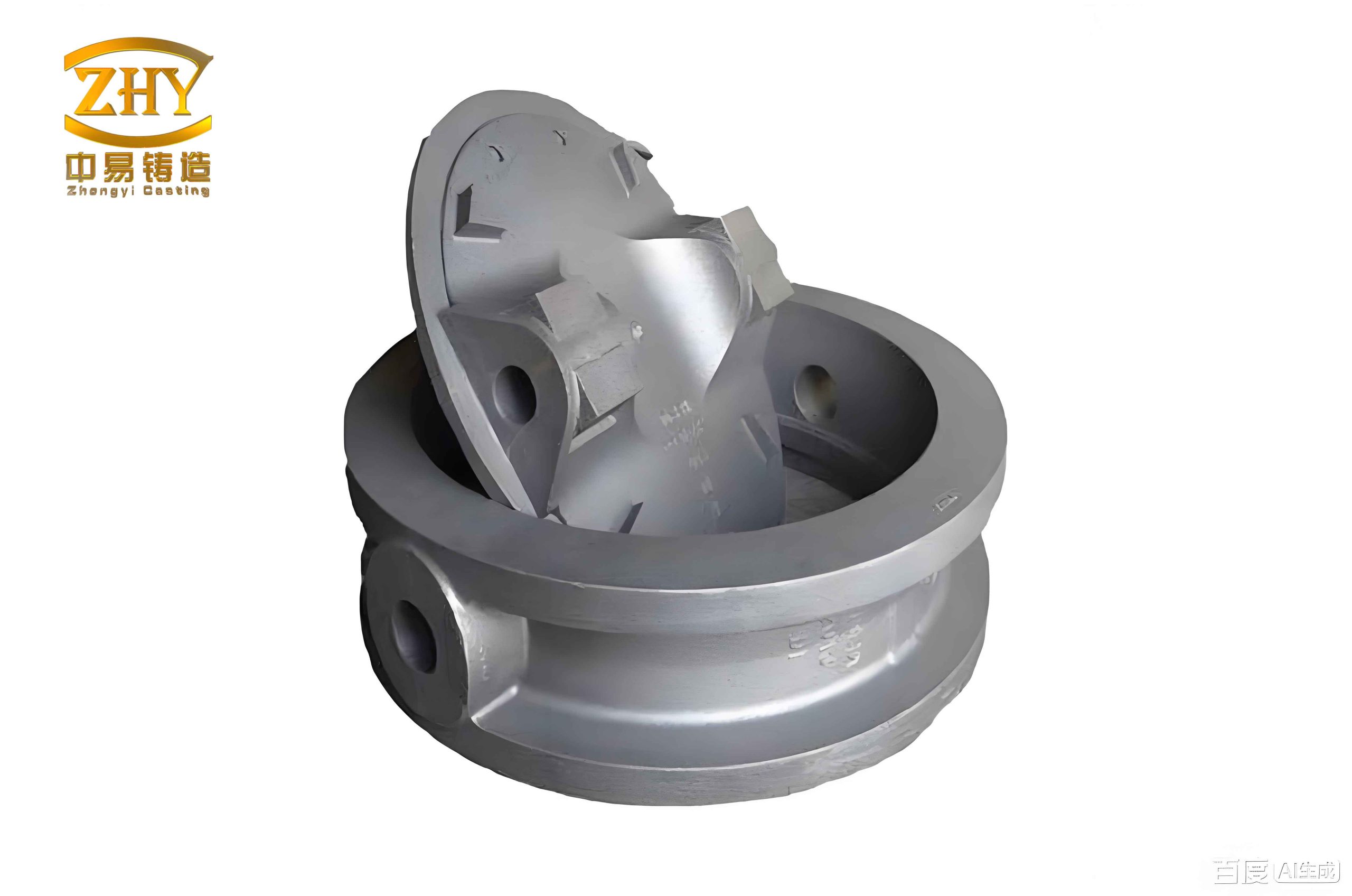
Foundational Principles of Solidification Simulation
The accuracy of any casting simulation hinges on solving the governing equations of heat transfer and fluid flow within the complex geometry of the mold-casting system. The core of solidification modeling is the transient heat conduction equation, which accounts for the release of latent heat during the phase change from liquid to solid:
$$ \rho c_p \frac{\partial T}{\partial t} = \nabla \cdot (k \nabla T) + \dot{Q}_L $$
Where \( \rho \) is density, \( c_p \) is specific heat, \( T \) is temperature, \( t \) is time, \( k \) is thermal conductivity, and \( \dot{Q}_L \) is the latent heat source term. For a binary alloy solidifying over a temperature range, the fraction of solid \( f_s \) is a critical variable, often modeled using relationships like the Scheil equation or lever rule for microsegregation. The latent heat release is then coupled to the rate of solid fraction change:
$$ \dot{Q}_L = \rho L \frac{\partial f_s}{\partial t} $$
Where \( L \) is the latent heat of fusion. The boundary condition at the casting-mold interface is crucial and is given by:
$$ -k \frac{\partial T}{\partial n} = h (T_{cast} – T_{mold}) $$
Here, \( h \) is the interfacial heat transfer coefficient (IHTC), and \( n \) is the normal direction to the surface. The IHTC is not a constant but a complex function of gap formation due to air entrapment and contraction, making accurate defect prediction dependent on its proper characterization.
Defect prediction algorithms, such as for shrinkage porosity, often use criteria functions. The Niyama criterion is a widely accepted metric for steel castings, predicting the likelihood of microporosity based on local thermal conditions at the end of solidification:
$$ N_y = \frac{G}{\sqrt{\dot{T}}} $$
Where \( G \) is the temperature gradient and \( \dot{T} \) is the cooling rate. Regions where \( N_y \) falls below a critical threshold (e.g., ~1 °C1/2·s1/2·cm-1 for steel) are flagged as potential shrinkage porosity sites. Simulation software like ViewCast implements these physical models to provide visual maps of temperature, solid fraction, and defect indices throughout the solidification process.
Case Study: Initial Process Design and Simulation Analysis
The subject component is a large, disk-shaped top cover with significant variation in wall thickness. Its key dimensions and material specifications are summarized below:
| Parameter | Value |
|---|---|
| Material | ZG270-500 (Cast Steel) |
| Liquidus Temperature | 1512 °C |
| Solidus Temperature | 1458 °C |
| Pouring Temperature | 1560 °C |
| Max Wall Thickness | 85 mm |
| Min Wall Thickness (Inner Cone) | 40 mm |
| Casting Weight | 1650 kg |
The initial casting process utilized a water glass sand mold with an open gating system. The feeding system employed three sizes of conventional side risers (or “breast risers”), placed on the thicker outer rim and central areas. The 3D model of this initial setup was meshed (~2 million elements) and simulated in ViewCast. The simulation parameters included an interfacial heat transfer coefficient of 1100 W/(m²·K) and a mold initial temperature of 25 °C.
The filling simulation confirmed no major issues like cold shuts or mistruns. However, the solidification simulation revealed a critical flaw. The time-sequence of solid fraction development showed the premature formation of isolated liquid pools, or “hot spots,” within the thin inner conical section of the casting well before the adjacent risers had solidified. These isolated regions, cut off from liquid metal supply, are inevitable sites for shrinkage defects. The final shrinkage prediction map clearly flagged extensive porosity in this inner cone area. This result was later validated by ultrasonic testing on a physical casting, confirming the simulation’s accuracy. The root cause was identified as insufficient feeding: the risers were too few and their effective feeding range did not cover the entire thin-walled section. For a steel plate-like section of 40mm thickness, the theoretical feeding distance of a conventional riser is approximately 4.5 times the plate thickness, or about 180mm. The initial riser layout failed to provide overlapping feeding zones across the entire cone.
A Systematic Optimization Framework for Sand Casting Products
Based on the simulation diagnosis, a multi-pronged optimization strategy was implemented to achieve directional solidification from the casting’s thickest sections (the base) towards the risers located at the top (the inner and outer rims). This is the fundamental principle for producing sound sand casting products.
1. Riser System Redesign: The primary remedy was a significant increase in the number of risers specifically targeting the problematic inner cone. The required number was calculated by dividing the cone’s perimeter by the effective feeding distance of a new, optimally sized riser. The riser modulus method was used for sizing. The modulus \( M \) of a casting section is its volume-to-surface-area ratio \( (V/A) \). For a plate, \( M \approx \text{thickness}/2 \). The inner cone section modulus is thus ~20mm. A riser must have a larger modulus to solidify last. For a cylindrical side riser, \( M_{riser} = d/4 \) (ignoring heat transfer from the top), where \( d \) is diameter. To ensure adequate feeding, \( M_{riser} = 1.2 \times M_{casting} \). For a rectangular (腰型) riser, an equivalent modulus calculation was performed. Furthermore, insulating riser sleeves were specified. These sleeves dramatically reduce the heat loss from the riser, represented in the simulation by modifying the boundary condition (effectively lowering the ‘k’ or ‘h’ value for the riser wall), which keeps the riser liquid longer and improves its feeding efficiency. This is a key technique for enhancing yield in steel sand casting products.
2. Strategic Use of Chills: To enforce directional solidification and define distinct feeding zones, multiple rows of external chills were placed on the thickest part of the casting, opposite the inner cone risers. Chills, typically made of iron or copper, have high thermal conductivity and heat capacity. They act as a heat sink, accelerating solidification in the region they contact. In the simulation, this is modeled by applying a very high local heat transfer coefficient or by explicitly modeling the chill as a solid with its own thermal properties. The effect is to create a steep temperature gradient, pulling solidification fronts from the chilled area towards the risers, thereby preventing the formation of isolated hot spots between risers.
3. Gating System Consideration: While the original gating was adequate for fill, the optimization also considered its impact on thermal gradients. A bottom-gating system, which fills the mold from the bottom up, generally promotes favorable thermal gradients by heating the upper parts of the mold (where risers are placed) and keeping the lower parts cooler. This was maintained in the optimized design to support the overall directional solidification plan.
The table below contrasts the key features of the initial and optimized processes:
| Feature | Initial Process | Optimized Process |
|---|---|---|
| Number of Riser | 17 | 33 |
| Riser Type | Conventional Sand Riser | Insulating Sleeve Riser |
| Auxiliary Cooling | None | Multiple Rows of External Chills |
| Feeding Coverage | Incomplete (Gaps in inner cone) | Complete, overlapping zones |
| Solidification Pattern | Multiple isolated liquid pools | Directional, bottom-to-top |
Simulation and Physical Validation of the Optimized Process
The 3D model of the fully optimized process—including new risers, insulating sleeves, and chills—was simulated under identical boundary conditions. The filling simulation showed a smooth, progressive fill without turbulence. The solidification simulation told the success story: the chilled regions solidified first, acting as a starting point. A clear, advancing solidification front then moved from the thick base, through the casting walls, and finally into the risers. The isolated liquid zones were completely eliminated from the casting body and confined solely to the risers, which remained liquid longest as intended.
The final shrinkage prediction map confirmed the elimination of shrinkage porosity and cavities within the casting proper. All predicted defects were successfully migrated into the risers, which are later removed. This virtual result was the green light for production.
A physical casting was produced using the optimized sand molding process. Post-casting, it underwent non-destructive testing. Ultrasonic inspection (per relevant standards) confirmed the absence of internal shrinkage defects, aligning perfectly with the simulation prediction. Furthermore, mechanical and metallurgical quality was verified. Hardness tests on attached test coupons showed consistent and acceptable values. Microstructural analysis revealed a normal as-cast steel microstructure consisting of ferrite and pearlite, with no anomalous phases indicative of casting-related problems. The final component met all specified technical requirements, demonstrating the efficacy of the simulation-driven optimization for complex sand casting products.
Conclusions and Broader Implications
This detailed case study underscores the transformative power of numerical simulation in modern foundry engineering, particularly for challenging steel sand casting products. The initial process, designed with traditional guidelines, failed to prevent significant shrinkage defects in a large, thin-walled area. ViewCast simulation provided not just a prediction of the failure but, more importantly, a clear visualization of the underlying thermal mechanism—insufficient and improperly coordinated feeding.
The optimization strategy was holistic, addressing the root cause:
- Quantitative Feeding: Increasing riser count based on modulus and feeding distance calculations.
- Enhanced Feeding Efficiency: Employing insulating riser sleeves to improve yield and feeding power.
- Controlled Solidification: Implementing chills to establish and enforce the desired directional solidification pattern.
The re-simulation of this optimized design provided a high degree of confidence in its success before any metal was poured, eliminating costly trial runs.
The broader implication is that the methodology demonstrated here—diagnostic simulation followed by systematic, physics-based optimization of the feeding and cooling systems—is universally applicable. It represents a best-practice approach for developing robust processes for a wide array of complex sand casting products, from heavy-sectioned mill housings to intricate valve bodies. As simulation software continues to advance, incorporating more sophisticated models for microstructure prediction and stress analysis, its role as an indispensable tool for achieving first-time-right quality in metal casting will only grow more pronounced.