
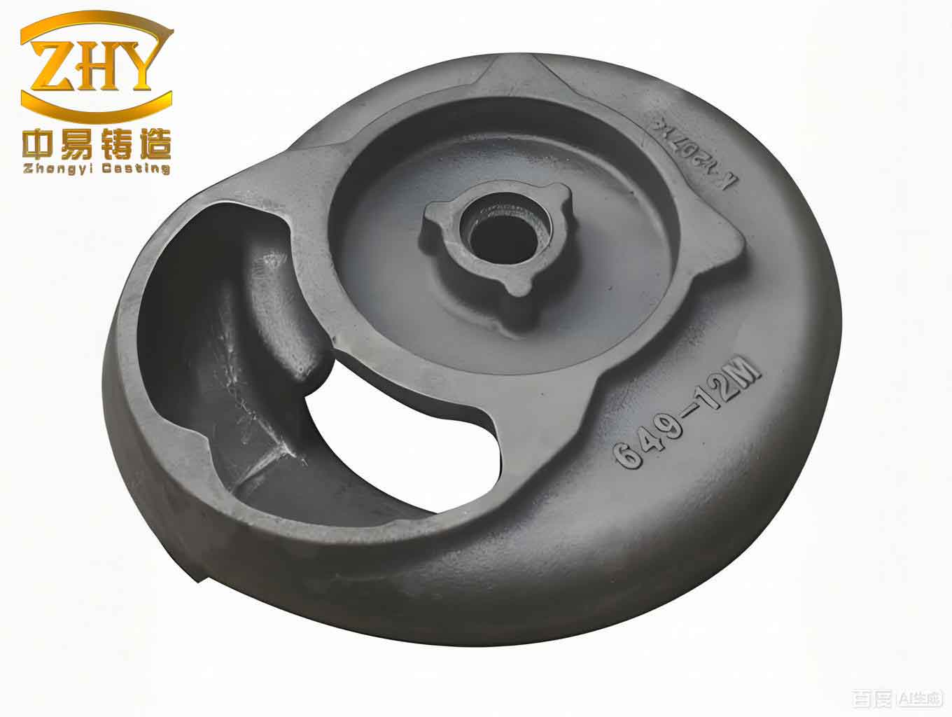
As a practitioner in the field of metal casting, I have extensively worked with sand casting, a time-honored metal forming technique renowned for its cost-effectiveness and high adaptability to complex geometries. This process is pivotal in manufacturing sand casting products across industries such as machinery, automotive, aerospace, and heavy equipment. Despite its advantages, producing intricate structural components via sand casting presents significant challenges, particularly in controlling quality and optimizing工艺 parameters. The advent of Computer-Aided Engineering (CAE) technologies, especially casting simulation software, has revolutionized the design and analysis of sand casting processes, offering new avenues to enhance the reliability and efficiency of sand casting products. In this article, I will delve into the工艺 design and simulation analysis for complex structural parts, emphasizing how modern tools can mitigate traditional pitfalls and improve outcomes for sand casting products.
The foundation of successful sand casting lies in meticulous工艺 design, which encompasses several critical aspects. First,工艺 analysis involves selecting appropriate materials and parameters to ensure dimensional accuracy and structural integrity. For instance, the use of furan resin self-hardening sand is common to reduce surface defects and enhance the density of sand casting products. Key parameters include dimensional tolerances, mass tolerances, and shrinkage rates. Typically, for complex parts, a dimensional tolerance grade of CT11 is adopted to account for free contraction during cooling, while a mass tolerance grade of MT10 ensures consistency in weight, often within ±4% of the nominal value. Shrinkage, a crucial factor, can be expressed mathematically. For materials like HT250, the linear shrinkage rate ($S_l$) is often set at 0.9%, derived from the volumetric shrinkage ($S_v$) relationship. The volumetric shrinkage during solidification can be modeled as:
$$ S_v = \frac{V_l – V_s}{V_l} \times 100\% $$
where $V_l$ is the volume of liquid metal and $V_s$ is the volume of the solid casting. For many ferrous alloys, this translates to a linear shrinkage approximation:
$$ S_l \approx \frac{S_v}{3} $$
Thus, for HT250 with $S_v \approx 2.7\%$, $S_l$ is around 0.9%. Properly accounting for this prevents cracking and distortion in sand casting products. To summarize typical工艺 parameters, I present Table 1 below.
| Parameter | Value/Range | Description |
|---|---|---|
| Dimensional Tolerance Grade | CT11 | Accounts for free contraction; common for complex sand casting products. |
| Mass Tolerance Grade | MT10 | Ensures weight consistency within ±4% for sand casting products. |
| Linear Shrinkage Rate | 0.9% | For HT250; critical to avoid defects in sand casting products. |
| Sand Type | Furan Resin Self-Hardening | Reduces surface defects and improves density of sand casting products. |
Next, the selection of pouring position and parting plane is vital for the quality of sand casting products. In complex components, such as those with sliding surfaces or large planes, orienting critical surfaces downward leverages gravity to facilitate metal flow, minimize turbulence, and reduce gas entrapment. For example, positioning a swallowtail guide surface downward and a large plane upward enhances filling efficiency and crystallization quality. This alignment can be analyzed using fluid dynamics principles. The pressure head ($h$) in a浇注 system can be estimated by:
$$ h = \frac{P}{\rho g} $$
where $P$ is the metallostatic pressure, $\rho$ is the metal density, and $g$ is gravity. Optimizing $h$ through proper orientation reduces defects in sand casting products.
浇注 system design is another cornerstone, directly impacting the integrity of sand casting products. A well-designed system includes ingates, runners, and risers to manage metal flow, temperature distribution, and feeding. For complex parts, a stepped inclined浇注 system is often employed, where ingates are arranged in a阶梯式 fashion to control filling sequence and velocity. This minimizes冲刷 and gas porosity. The flow rate ($Q$) through an ingate can be described by:
$$ Q = A \cdot v $$
where $A$ is the cross-sectional area and $v$ is the flow velocity. By adjusting $A$ and $v$, engineers can ensure uniform filling of sand casting products. Riser design is crucial for compensating shrinkage; the riser volume ($V_r$) should satisfy:
$$ V_r \geq V_c \cdot \beta $$
where $V_c$ is the volume of the casting section being fed, and $\beta$ is the shrinkage factor. Proper riser placement atop critical sections captures slag and gases, enhancing the quality of sand casting products. Table 2 summarizes key浇注 system parameters.
| Component | Design Feature | Purpose |
|---|---|---|
| Ingates | Stepped inclined layout | Controls flow sequence, reduces turbulence in sand casting products. |
| Risers | Top-placed, volume-optimized | Feeds shrinkage, traps slag in sand casting products. |
| Flow Velocity | 0.5-1.0 m/s | Balances filling and defect avoidance for sand casting products. |
Moving to simulation analysis, CAE tools like Anycasting software have become indispensable for optimizing sand casting products. Preliminary simulation involves modeling the filling and solidification processes to identify potential defects. The filling phase can be simulated using the Navier-Stokes equations for incompressible flow:
$$ \rho \left( \frac{\partial \mathbf{v}}{\partial t} + \mathbf{v} \cdot \nabla \mathbf{v} \right) = -\nabla p + \mu \nabla^2 \mathbf{v} + \rho \mathbf{g} $$
where $\mathbf{v}$ is the velocity vector, $p$ is pressure, $\mu$ is dynamic viscosity, and $\mathbf{g}$ is gravitational acceleration. This helps visualize flow patterns,冷隔, and gas entrapment in sand casting products. Solidification simulation employs heat transfer equations, such as the Fourier law:
$$ \frac{\partial T}{\partial t} = \alpha \nabla^2 T $$
where $T$ is temperature, $t$ is time, and $\alpha$ is thermal diffusivity. By solving these equations, engineers predict temperature gradients and shrinkage porosity in sand casting products. For instance,模拟 might reveal冷隔 in thin sections, prompting redesign of ingates. Table 3 shows typical simulation outcomes and their implications for sand casting products.
| Simulation Phase | Key Output | Impact on Sand Casting Products |
|---|---|---|
| Filling | Flow velocity, turbulence zones | Identifies gas porosity risks in sand casting products. |
| Solidification | Temperature fields, solidification time | Predicts shrinkage defects in sand casting products. |
| Stress Analysis | Thermal stress distribution | Highlights cracking tendencies in sand casting products. |
Based on simulation results,工艺 optimization measures are implemented to refine sand casting products. First, adjusting the浇注 system may involve relocating ingates or modifying their sizes to improve flow uniformity. For example, if模拟 shows stagnant flow, the ingate area can be recalculated using the continuity equation:
$$ A_1 v_1 = A_2 v_2 $$
to ensure steady filling of sand casting products. Second, adding risers enhances feeding; the riser efficiency ($\eta_r$) can be optimized by:
$$ \eta_r = \frac{V_{\text{usable}}}{V_r} $$
where $V_{\text{usable}}$ is the volume effectively fed to the casting. Third, incorporating chills accelerates cooling in thick sections, refining the microstructure of sand casting products. The chill effect can be modeled using heat flux equations:
$$ q = -k \frac{dT}{dx} $$
where $q$ is heat flux, $k$ is thermal conductivity, and $\frac{dT}{dx}$ is the temperature gradient. Fourth, optimizing the solidification sequence ensures directional solidification, reducing internal stresses in sand casting products. This often involves strategic placement of chills and risers, guided by simulated temperature profiles. These measures collectively enhance the mechanical properties and defect reduction for sand casting products. To quantify optimization benefits, Table 4 compares pre- and post-optimization parameters for sand casting products.
| Parameter | Pre-Optimization | Post-Optimization | Improvement for Sand Casting Products |
|---|---|---|---|
| Defect Rate | 15% | 5% | Reduced porosity and冷隔 in sand casting products. |
| Solidification Time | Uneven | Controlled gradient | Enhanced structural integrity of sand casting products. |
| Material Yield | 75% | 85% | Increased efficiency in producing sand casting products. |
In conclusion, the integration of CAE simulation into traditional sand casting processes has profoundly improved the quality and efficiency of manufacturing complex structural components. By leveraging numerical models and optimization strategies, we can address inherent challenges, such as shrinkage and flow-related defects, leading to superior sand casting products. The future of this field lies in the convergence of simulation with artificial intelligence and machine learning, enabling predictive analytics and autonomous工艺 adjustments. As these technologies evolve, they will further streamline the design cycle, reduce costs, and enhance the performance of sand casting products across various industries. Ultimately, the continuous advancement in sand casting methodologies underscores its enduring relevance in modern manufacturing, ensuring that sand casting products meet ever-higher standards of precision and reliability.