
In my extensive experience within the foundry industry, addressing sand casting defects remains a perennial challenge, particularly for complex, thin-walled castings like cylinder heads for heavy-duty vehicles. Porosity, a common sand casting defect, can severely compromise the structural integrity and pressure tightness of these critical components. This article delves into my firsthand account of tackling porosity defects during the trial production of a six-cylinder cast iron cylinder head using green sand molding. The focus is on systematic analysis and the implementation of targeted process improvements that led to effective control of this pervasive sand casting defect.
The cylinder head in question, with overall dimensions of 883 mm × 340 mm × 133 mm and a minimum wall thickness of 5 mm, is a representative and technologically demanding component for modern heavy-duty diesel engines. Its material specification is HT250 gray iron, with a rough casting weight of approximately 110 kg. The initial production setup employed a common method: green clay sand molds produced via static pressure molding, with core assemblies primarily made from hot-box coated sand (resin-coated sand), arranged horizontally in a one-casting-per-mold configuration. It was in this setup that significant porosity, a classic sand casting defect, manifested predominantly on the oil-cover shell surface of the casting.
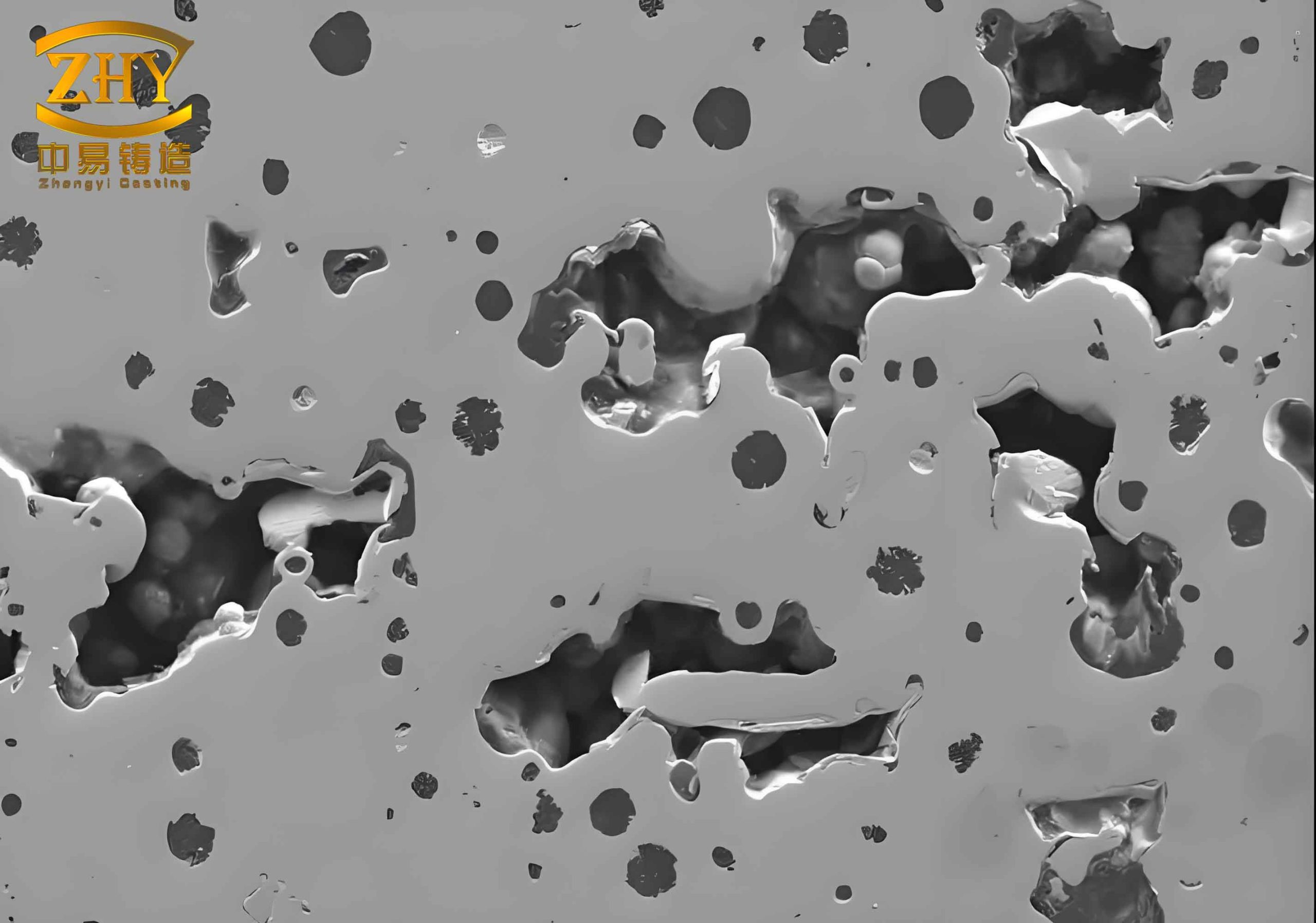
The initial struggle with this sand casting defect provided crucial insights. The porosity appeared primarily at the two ends of the oil-cover shell surface (locations analogous to points A and B in a typical layout) and on raised bosses (similar to points C and D). Analysis revealed that the defects at the ends were mostly precipitating or micro-shrinkage porosity, with a minor fraction being invasive gas holes. The defects on the bosses were predominantly of the precipitating type. Understanding the root causes was essential for formulating a solution to this persistent sand casting defect.
Comprehensive Analysis of Porosity Formation Mechanisms
To effectively combat any sand casting defect, one must first understand its genesis. In this case, the porosity arose from a confluence of factors related to mold design, core material, sand properties, and metal treatment. My investigation identified several key contributors.
1. Suboptimal Temperature Gradient from Gating Design: The initial gating system was a middle-level pour scheme, with gates located either on the intake or exhaust manifold sides. This design created an unfavorable temperature distribution within the mold cavity. The metal temperature gradient was higher at the bottom and lower at the top, which is detrimental for the escape of dissolved gases and promotes gas entrapment near the upper surfaces—precisely where the oil-cover shell is located. This directly led to a widespread sand casting defect. The thermal profile can be conceptually described by the heat transfer equation during filling:
$$ \frac{\partial T}{\partial t} + \vec{v} \cdot \nabla T = \alpha \nabla^2 T $$
where \(T\) is temperature, \(t\) is time, \(\vec{v}\) is the fluid velocity vector, and \(\alpha\) is the thermal diffusivity. An adverse \(\nabla T\) (temperature gradient) impedes directional solidification favorable to gas expulsion.
2. Non-Uniform Filling from Top Gating: In subsequent trials, the system was modified to a top gating approach by converting one of the existing risers on the oil-cover surface into a pouring gate. However, a critical oversight was that the total cross-sectional area of these ingates (\( \Sigma F_{ingate} \)) vastly exceeded the choke area of the gating system (\( \Sigma F_{choke} \)). This caused an unbalanced flow: a massive influx of metal in the central region of the cavity and a trickle feed at the two ends. Consequently, the temperature distribution became highly non-uniform—hot in the center and cool at the ends—creating localized zones prone to gas precipitation and another manifestation of the sand casting defect at the extremities.
3. Inappropriate Core Sand Characteristics: The properties of the coated sand used for the complex water jacket core played a significant role. During certain trial phases, the sand fineness was too high (main grain size 50/100 mesh) and its gas evolution was excessive (>15 mL/g). The gas evolution potential (\(Q\)) of a sand can be a major source for invasive porosity, a severe sand casting defect. The total gas pressure (\(P_{gas}\)) invading the metal can be related to the sand’s gas generation rate and permeability:
$$ P_{gas} = f(Q, t, \kappa) $$
where \(Q\) is gas evolution, \(t\) is time, and \(\kappa\) is permeability. High \(Q\) and low \(\kappa\) lead to high \(P_{gas}\), increasing the risk of gas penetration into the solidifying metal.
4. Inadequate Mold and Core Venting: The use of a standard flask (1200 mm × 800 mm × 330 mm) meant the cope was disproportionately tall for this casting, which was entirely housed in the drag. Coupled with low permeability (<150) of the backing sand, this setup hindered the escape of gases generated from both the mold and the cores. The permeability \(\kappa\) is a critical factor in preventing this type of sand casting defect, as defined by Darcy’s law for flow through porous media:
$$ v = -\frac{\kappa}{\mu} \nabla P $$
where \(v\) is superficial velocity, \(\mu\) is gas viscosity, and \(\nabla P\) is pressure gradient. Low \(\kappa\) necessitates a steeper \(\nabla P\) to vent gases, which may not be achievable, leading to gas entrapment.
5. Poor Metal Quality: The base iron was melted in a cupola furnace. While cost-effective, cupola iron typically contains higher levels of dissolved gases (like hydrogen and nitrogen) and non-metallic inclusions compared to electric furnace melts. Without proper ladle treatment, these gases remain in solution and precipitate upon solidification, causing pinhole porosity. The solubility of gas in liquid iron decreases sharply upon solidification. The relationship is often given by Sieverts’ law for diatomic gases:
$$ S = k \sqrt{P} $$
where \(S\) is solubility, \(k\) is the equilibrium constant, and \(P\) is the partial pressure of the gas above the melt. During solidification, the effective \(P\) for gas in the liquid increases as the volume decreases, leading to supersaturation and nucleation of bubbles—the genesis of this sand casting defect.
| Factor | Specific Issue | Type of Porosity Promoted | Governing Principle/Parameter |
|---|---|---|---|
| Gating System | Middle-pour creating inverse T-gradient | Precipitating, Invasive | Temperature Gradient (\( \nabla T \)) |
| Gating System | Unbalanced top-pour flow | Precipitating (at ends) | Flow Uniformity, \( \Sigma F_{ingate} / \Sigma F_{choke} \) |
| Core Sand | Fine grain, high gas evolution | Invasive | Gas Evolution \(Q\), Permeability \(\kappa\) |
| Mold Sand | Low backing sand permeability | Invasive | Permeability \(\kappa\) |
| Metal Treatment | High dissolved gas & inclusions | Precipitating (Pinhole) | Gas Solubility \(S\), Inclusion Content |
Systematic Process Measures to Mitigate the Sand Casting Defect
Based on this analysis, a multi-pronged strategy was implemented to attack the sand casting defect from all angles. The following sections detail the specific process optimizations I led.
1. Redesign of the Gating and Feeding System
The gating system overhaul was the most impactful change. The middle-pour system was completely abandoned in favor of a carefully designed top-pour system. The original risers on the oil-cover shell were eliminated, and a new gating system was introduced directly onto that surface. This ensured a favorable temperature gradient: hotter metal at the top (near the gates) and cooler metal at the bottom, promoting directional solidification from the drag upward and allowing gases to migrate toward the feeding sources or the mold atmosphere.
Furthermore, the critical issue of unbalanced flow was corrected by rigorously applying hydraulic principles. The gating system was designed to be pressurized, with the choke at the sprue base. The total ingate area was calculated to match the choke area, ensuring balanced flow across all ingates. The basic continuity and Bernoulli’s equation govern this:
$$ A_1 v_1 = A_2 v_2 $$
$$ P + \frac{1}{2} \rho v^2 + \rho g h = \text{constant} $$
where \(A\) is area, \(v\) is velocity, \(P\) is pressure, \(\rho\) is density, and \(h\) is height. By setting \( \Sigma F_{ingate} = \Sigma F_{choke} \), the pressure at each ingate is equalized, leading to simultaneous filling across the cavity length. This eliminated the cold zones at the ends, drastically reducing the sand casting defect in those regions.
| Parameter | Initial Middle-Pour | Unbalanced Top-Pour | Optimized Top-Pour |
|---|---|---|---|
| Pouring Location | Manifold Side (Middle Height) | Oil-Cover Shell (Top) | Oil-Cover Shell (Top) |
| Temperature Gradient | Bottom-High, Top-Low (Adverse) | Center-High, Ends-Low (Non-uniform) | Top-High, Bottom-Low (Favorable) |
| \( \Sigma F_{ingate} / \Sigma F_{choke} \) Ratio | N/A (Different design) | > 3.0 (Highly Unbalanced) | ≈ 1.0 (Balanced) |
| Observed Porosity Severity | Severe, widespread | Moderate, localized at ends | Minor to None |
| Primary Defect Type Addressed | Precipitating & Invasive | Precipitating at ends | All types |
2. Optimization of Core Sand Selection and Venting
Specifications for the hot-box coated sand were tightened. We reverted to and standardized a coarser grain distribution, primarily 40/70 mesh, which offers a better balance between surface finish and permeability. The gas evolution was strictly controlled to be below 15 mL/g. The relationship between grain size, permeability, and gas evolution is complex, but generally, coarser grains increase permeability, reducing back-pressure. The effective permeability for gas flow can be approximated by the Kozeny-Carman equation:
$$ \kappa \propto \frac{d^2 \phi^3}{(1-\phi)^2} $$
where \(d\) is mean grain diameter and \(\phi\) is porosity. Increasing \(d\) significantly boosts \(\kappa\), facilitating gas escape and mitigating this core-related sand casting defect.
Additionally, the core and mold venting were enhanced. While the core boxes had integral vent channels, their alignment with the mold vents was checked. In the tall cope, five to six additional vent holes of 12-16 mm diameter were drilled at strategic locations to provide direct paths for gases to escape to the atmosphere, further reducing the potential for invasive sand casting defects.
3. Enhancement of Mold Sand Properties
The green sand system was adjusted to improve its venting capacity. The key parameter is permeability. We optimized the sand mix and compaction process to achieve a consistent permeability in the range of 150-200 for the backing sand. This was achieved by controlling the moisture content, clay content, and grain distribution. The standard foundry test for permeability measures the volume of air passing through a standardized sand specimen under a pressure drop. While empirical, maintaining a higher value directly correlates with a reduced risk of gas-related sand casting defects.
4. Advanced Molten Metal Treatment and Inoculation
Recognizing that the cupola metal was a source of gases and inclusions, implementing ladle metallurgy was crucial. Two treatments were adopted:
A. Degassing/Purification: A proprietary “NC” purifying agent was added to the ladle at a rate of 0.05% of the metal weight. This agent likely functions as a scavenger, reacting with dissolved gases (like [H], [N]) and non-metallic inclusions to form stable compounds that float to the slag layer. The kinetics of degassing can be modeled as a first-order reaction:
$$ \frac{d[C_{gas}]}{dt} = -k_{degas} (C_{gas} – C_{eq}) $$
where \(C_{gas}\) is the dissolved gas concentration, \(C_{eq}\) is the equilibrium concentration at the gas/liquid interface, and \(k_{degas}\) is a rate constant enhanced by the purifier. This treatment directly attacks the root cause of precipitating sand casting defects.
B. Inoculation and Secondary Purification: A rare-earth silicon ferroalloy (containing ~30% RE, ~40% Si) was added at 0.3-0.4% for inoculation. Rare earth elements are powerful desulfurizers and deoxidizers. They modify the morphology of graphite and eutectic cells, but also getter trace elements that can promote pinhole formation. The inoculation process improves the metallurgical quality, making the iron less susceptible to micro-shrinkage, a form of sand casting defect. The effectiveness can be related to the increase in nucleation sites, described by the heterogeneous nucleation rate:
$$ I = I_0 \exp\left(-\frac{\Delta G^*}{k_B T}\right) $$
where \(\Delta G^*\) is the reduced activation energy due to inoculant particles, \(k_B\) is Boltzmann’s constant, and \(T\) is temperature. More nucleation sites lead to finer graphite and a more uniform structure, reducing interdendritic shrinkage porosity.
| Process Area | Specific Action | Mechanism of Action | Quantitative Target/Parameter | Impact on Porosity Defect |
|---|---|---|---|---|
| Gating Design | Change to balanced top-pour | Creates favorable T-gradient & uniform filling | \( \Sigma F_{ingate} = \Sigma F_{choke} \) | Drastic reduction (Primary factor) |
| Core Sand | Use coarse, low-gas sand | Reduces gas generation & improves venting | Grain: 40/70 mesh, Gas Evol. < 15 mL/g | Significant reduction in invasive defects |
| Mold Venting | Add vent holes in cope | Provides escape path for mold/core gases | 5-6 holes, Ø12-16 mm | Reduces back-pressure, prevents invasion |
| Mold Sand | Optimize sand mix | Increases mold gas permeability | Permeability: 150-200 | Supports overall gas evacuation |
| Metal Treatment | Add “NC” Purifier (0.05%) | Removes dissolved gases and inclusions | Ladle addition post-tap | Reduces source of precipitating gases |
| Metal Treatment | Add RE-Si-Fe inoculant (0.3-0.4%) | Modifies structure, getters impurities | Ladle addition pre-pour | Reduces micro-shrinkage tendency |
Theoretical Framework and Quantitative Relationships
To generalize the approach for preventing such sand casting defects, it’s useful to model the overall risk. The propensity for porosity formation \( \Pi \) can be conceptualized as a function of multiple variables:
$$ \Pi = f( \nabla T_{crit}, \Delta P_{gas}, [Gas]_{metal}, t_{local} ) $$
where:
- \( \nabla T_{crit} \) is the critical temperature gradient influencing feeding and gas escape direction. A positive gradient (hot top, cold bottom) reduces \( \Pi \).
- \( \Delta P_{gas} \) is the pressure difference between the gas sources (core/mold/metal) and the metallostatic pressure. It is governed by: $$ \Delta P_{gas} = P_{gen} – (\rho_m g h + P_{atm}) $$ where \(P_{gen}\) is gas generation pressure from sand (function of \(Q, \kappa\)), \(\rho_m\) is metal density, \(h\) is metal head height, and \(P_{atm}\) is atmospheric pressure. Minimizing \(P_{gen}\) and maximizing \(\rho_m g h\) reduces \( \Delta P_{gas} \) and the risk of invasion.
- \( [Gas]_{metal} \) is the concentration of dissolved gases in the molten metal, governed by Sieverts’ law and reduced by degassing.
- \( t_{local} \) is the local solidification time. Longer times can allow gas diffusion and bubble growth, but also aid in bubble floatation. For thin sections, it’s short, promoting gas entrapment. Chvorinov’s rule applies: $$ t_{local} = B \left( \frac{V}{A} \right)^n $$ where \(V/A\) is the modulus, and \(B\) and \(n\) are constants. A high modulus area solidifies last and may act as a sink for porosity if not properly fed.
The combined process measures effectively minimize each term in this \( \Pi \) function, thereby controlling the sand casting defect.
Results and Practical Outcomes
The implementation of these integrated measures transformed the production outcome. The severe, widespread sand casting defect observed in the initial trials was brought under control. The porosity on the oil-cover shell surface was reduced to sporadic, acceptable levels, and in many batches, eliminated entirely. The yield improved significantly, and the cylinder heads reliably passed stringent pressure tests and radiographic inspection.
The key learning was that no single silver bullet exists for complex sand casting defects like porosity. Instead, a systematic approach addressing every stage—from mold design and sand selection to metal treatment—is essential. Each factor interacts; for instance, excellent metal quality can be negated by poor venting, and a perfect gating design can fail if the cores produce excessive gas. Therefore, a holistic view of the entire process chain is paramount for defect prevention.
Extended Considerations and Future Directions
While the described measures successfully mitigated the sand casting defect in this specific case, the principles are widely applicable. In modern foundries, simulation software plays a vital role in predicting and optimizing these parameters. Tools that simulate mold filling, solidification, and even gas pressure buildup can proactively identify risk areas for sand casting defects.
Furthermore, the industry is exploring advanced sand binders with lower gas evolution, and improved melting and holding furnaces (like medium frequency induction) that inherently produce cleaner metal with lower gas content. Automated sand property control and real-time monitoring of metal chemistry are also becoming standard, providing tighter control over the variables that lead to sand casting defects.
In conclusion, my experience reaffirms that defeating the sand casting defect of porosity in complex castings requires deep process understanding, rigorous analysis, and disciplined execution across multiple fronts. By focusing on creating favorable thermal gradients, ensuring proper venting, selecting appropriate sand materials, and purifying the molten metal, foundries can achieve robust production of high-integrity castings like heavy-duty vehicle cylinder heads. The continuous pursuit of optimization in each of these areas remains the best strategy to minimize losses and ensure quality in sand casting operations.