
In my extensive analysis and practical observation of the lost foam casting (EPC) process for steel components, the prevalence and persistence of slag inclusion defects stand as a significant technical barrier. It is widely acknowledged within the foundry sector that these defects, alongside gas porosity and carbon pick-up, account for a dominant share of rejections, particularly for low-carbon and thick-section steel castings. This article synthesizes my understanding of the complex interplay of factors leading to slag inclusion formation, drawing from thermodynamic and kinetic principles, fluid dynamics of the filling process, and practical process metallurgy. My aim is to deconstruct the slag inclusion formation and movement mechanisms to outline viable pathways for mitigation.
1. The Pervasiveness and Characteristics of Slag Inclusions
The challenge of producing sound EPC steel castings cannot be overstated. Defects, primarily slag inclusion, gas holes, and inhomogeneous carburization, are not occasional but systemic, affecting a substantial majority of production runs. My assessment aligns with industry reports indicating scrap rates between 60% and 80% for certain casting categories. The morphology and distribution of these slag inclusion defects are distinct and offer clues to their origin.
Slag inclusion clusters are typically found not on the very surface but within a subsurface layer, approximately 1-3mm beneath the casting skin, extending inward for 10-30mm. Their appearance is irregular, with fuzzy, ill-defined boundaries and varying optical contrast under metallographic examination, indicating a non-metallic, often carbonaceous, composition intermingled with oxides. These clusters are diffuse and difficult to remove by machining. In thinner-section castings, defects tend to localize at junctions with gating or risering systems, where prolonged metal flow and thermal exposure exacerbate the problem. The visual manifestation of these defects is critical for diagnosis.
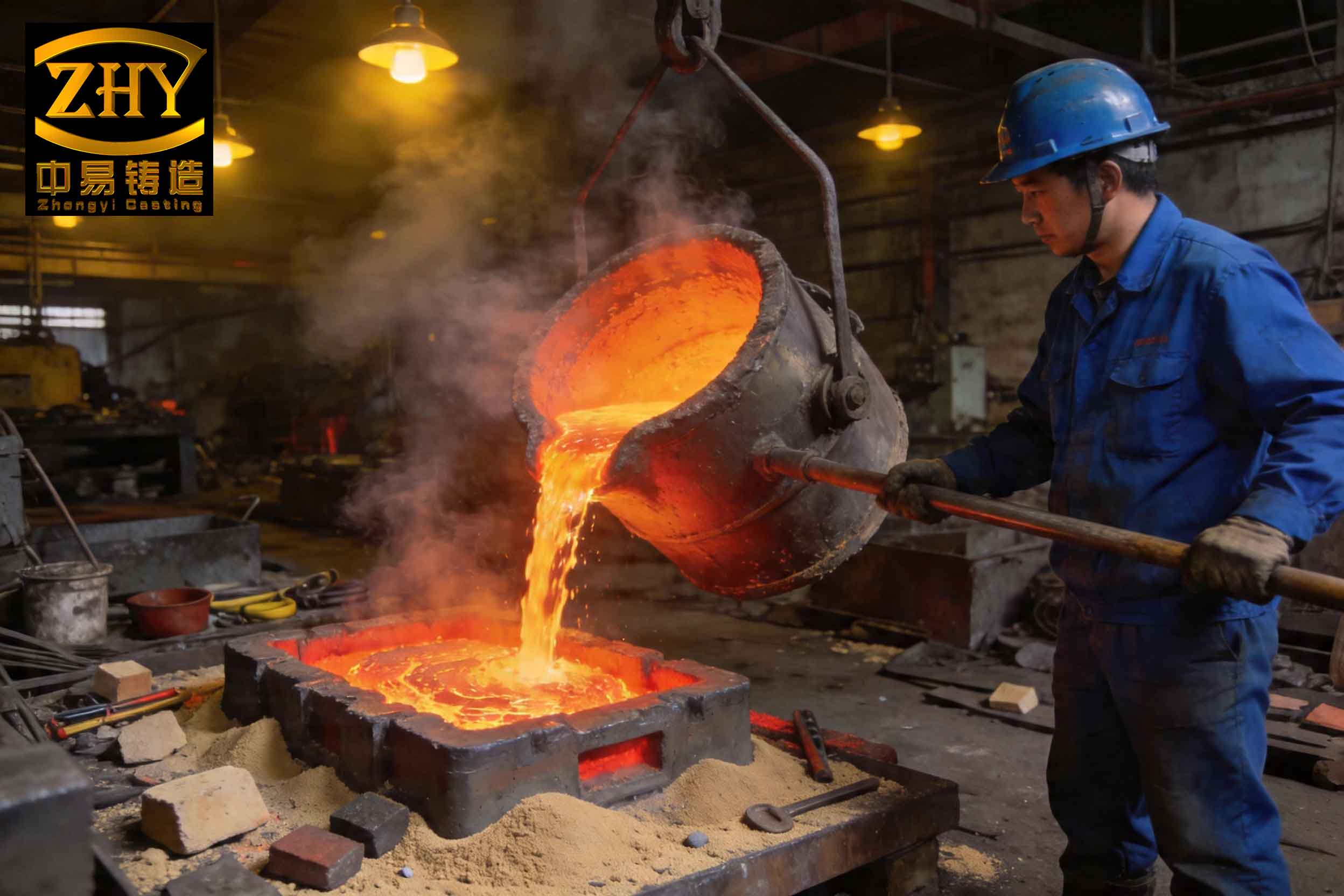
2. The Unique and Problematic Nature of EPC Filling
The root cause of the heightened susceptibility to slag inclusion lies in the fundamental departure of EPC filling from conventional empty-mold casting. The replacement of an air cavity with a combustible foam pattern radically alters the fluid dynamics.
In standard EPC practice for ferrous alloys, applying a vacuum to the sand mold is essential to maintain dimensional stability against the buoyancy forces of the liquid metal. However, this vacuum, while solving one problem, creates another. It induces a highly turbulent filling regime. The metal front does not advance as a coherent, laminar wave but as a chaotic, “mountain-ridge” profile with severe local fluctuations. This turbulence is a primary mechanism for the entrainment and dispersion of slag particles and gases throughout the liquid volume.
Furthermore, the vacuum exerts a powerful “wall attachment” effect. The pressure differential draws the liquid metal preferentially towards the mold walls coated with the refractory coating. This results in a rapid, U-shaped advancement of metal along the walls, forming a chilled shell that effectively creates a confined internal channel. This early solidification at the periphery traps the evolving pyrolysis gases from the decomposing foam core, increasing back-pressure and further destabilizing the central flow. It also creates a physical barrier that hinders the lateral escape of slag inclusion particles that might otherwise migrate to the mold wall-coating interface.
3. Origins and Fate of Slag: A Thermodynamic and Kinetic Analysis
The formation and final location of a slag inclusion within a casting are governed by its sources, its thermodynamic tendency to form or remain, and the kinetic conditions for its transport and removal.
3.1 Primary Sources of Slag Inclusions
The total population of inclusions present in the liquid steel at the moment of solidification is the sum of contributions from several stages:
| Source | Description | Typical Composition |
|---|---|---|
| 1. Pattern Pyrolysis Residue | Non-volatile carbonaceous deposits from incomplete combustion/pyrolysis of the EPS/EPMMA pattern. | Carbon clusters, soot, luminous flames condensates. |
| 2. Steelmaking Slags & Deoxidation Products | Carry-over slag from furnace/tundish or endogenous oxides (Al2O3, SiO2, MnO, etc.) from deoxidation. | Complex oxides (CaO-Al2O3-SiO2), alumina clusters. |
| 3. Re-oxidation Products | Oxides formed due to air entrainment or reaction with atmospheric/pattern gases during turbulent filling. | FeO, MnO, silicates. |
| 4. Mold Coatings & Adhesives | Dislodged fragments of the refractory coating or un-pyrolyzed adhesive from pattern assembly seams. | Aluminosilicates, carbon (from glue). |
3.2 Thermodynamic Driving Forces
The formation of oxide-type slag inclusion is favored thermodynamically under the oxidizing conditions that can arise. The reaction between dissolved elements in steel (e.g., Al, Si, Mn) and oxygen can be represented as:
$$ x[M]_{steel} + y[O]_{steel} \rightarrow M_xO_y (slag) $$
The Gibbs free energy change, $\Delta G = \Delta G^\circ + RT \ln Q$, must be negative for the reaction to proceed spontaneously. The high temperature and potential local oxygen enrichment from foam pyrolysis ($C_nH_m + O_2 \rightarrow CO, CO_2, H_2O$) or air entrainment provide a strong driving force for oxide formation, thereby increasing the slag inclusion load.
Furthermore, the pyrolysis of polystyrene follows complex pathways. The residual carbon, a primary constituent of one form of slag inclusion, is stable and its dissolution into steel is limited by kinetics and saturation, leading to its persistence as a solid particle.
3.3 Kinetic Barriers to Slag Removal
The key to preventing a slag inclusion defect is to ensure buoyant particles escape the solidifying metal. The terminal upward velocity ($v_t$) of a spherical particle (Stokes’ law regime) is given by:
$$ v_t = \frac{2}{9} \frac{(\rho_m – \rho_s) g r^2}{\eta} $$
where $\rho_m$ and $\rho_s$ are the density of metal and slag, $g$ is gravity, $r$ is the particle radius, and $\eta$ is the metal viscosity.
This equation highlights the critical parameters:
- Density Difference ($\rho_m – \rho_s$): Slag/oxide densities (~3-4 g/cm³) are much lower than steel (~7 g/cm³), providing buoyancy.
- Particle Radius ($r$): Velocity is proportional to $r^2$. Fine particles, especially sub-micron carbon clusters, have negligible flotation velocity ($v_t \rightarrow 0$) and are essentially trapped.
- Metal Viscosity ($\eta$): Increases as temperature drops, slowing flotation as solidification approaches.
The prevailing processing conditions in EPC create a hostile kinetic environment:
- Turbulence: Chaotic flow patterns keep particles in suspension, preventing their calm ascent to the surface. It also promotes particle breakup, reducing $r$.
- Vacuum Direction: Conventional side/bottom vacuum draws gas and fine particles horizontally towards the mold walls, directly opposing the natural buoyant vertical rise. This diverts particles into the wall attachment flow, embedding them in the subsurface layer.
- Short Process Time: The time available from filling end to complete solidification, especially in thin sections, is often less than the required flotation time for many particles.
The combined effect is summarized in the kinetic rate equation for slag removal, where the net accumulation rate is the balance between arrival (entrainment) and removal (flotation):
$$ \frac{dN}{dt} = R_{entrain} – R_{float} $$
where $R_{float} = A \cdot v_t \cdot n$, with $A$ being the available top surface area and $n$ the particle concentration. In EPC, $R_{entrain}$ is high due to turbulence and pattern decomposition, while $R_{float}$ is minimized by small $v_t$, obstructed top surface (by early crust), and competing lateral vacuum forces.
4. Pathways and Recommendations for Slag Inclusion Mitigation
Based on this mechanistic analysis, a multi-front strategy targeting the sources, formation, and removal kinetics of slag inclusion is essential.
4.1 Source Control: Minimizing Initial Slag Load
| Strategy | Action & Principle | Expected Effect |
|---|---|---|
| Steel Melt Purification | Employ efficient ladle refining, slag raking, and use of ceramic foam filters in the gating system. | Drastically reduces carry-over furnace slag and large deoxidation products. Filters trap particles > pore size. |
| Pattern Material & Assembly | Use low-density, high-volatility foam. Minimize adhesive use; ensure smooth seams without gaps or excess glue. Machine surfaces to minimize “craters”. | Reduces volume of carbonaceous residue. Eliminates sites for coating penetration and subsequent “coating nails” that break off to become inclusions. |
| Coating Integrity | Apply a uniform, adherent, and refractory coating with good high-temperature permeability. | Prevents coating spalling and erosion during filling, a direct source of mold material slag inclusion. |
4.2 Process Optimization: Enhancing Slag Flotation and Escape
Vacuum Management: This is perhaps the most critical lever. The vacuum level must be the minimum sufficient to prevent mold collapse. For steel castings, my recommendation is a range of 0.03 – 0.04 MPa (absolute pressure ~0.06-0.07 MPa). Even more beneficially, a top-draw vacuum system should be adopted. Applying vacuum from the top of the mold creates a vertical pressure gradient aligned with the buoyancy force, actively assisting the upward movement of slag and gas bubbles. The driving force for particle removal becomes a combination of buoyancy and pressure gradient flow:
$$ v_{effective} = v_t + K \frac{\Delta P}{\eta L} $$
where $K$ is permeability and $\Delta P/L$ is the pressure gradient. A top vacuum makes this term positive for upward motion.
Gating Design Philosophy: Adopt simple, short, and direct gating. Avoid one-mold multiple castings with long, tortuous runners. The goal is to minimize flow distance, velocity, and thus turbulence and temperature loss before the metal enters the cavity. A well-designed gating system that promotes a more quiescent fill, even in a vacuum environment, can significantly reduce $R_{entrain}$.
Thermal Controls: Optimize pouring temperature. Excessive superheat increases metal oxidation and pattern gasification violence, while too low a temperature increases viscosity $\eta$, hampers flotation, and promotes early freezing that traps slag. The ideal temperature is a compromise that ensures complete filling and adequate fluidity for slag flotation.
5. Conclusion
The formation of slag inclusion in EPC steel castings is not a random occurrence but a predictable consequence of the process physics. It originates from multiple, abundant sources inherent to the process and material set. The critical failure lies in the filling dynamics imposed by necessary process vacuum, which generates severe turbulence and a wall attachment effect that entrains and then laterally traps the slag particles. Thermodynamically, the conditions favor the formation of oxides and the persistence of carbon residues. Kinetically, the process actively works against the natural buoyant removal of these particles due to flow chaos, opposing pressure gradients, and limited available time.
Therefore, successful mitigation cannot rely on a single silver bullet. It requires an integrated approach: aggressively reducing the initial slag burden through melt treatment and careful pattern engineering, and fundamentally altering the kinetic landscape by minimizing vacuum to reduce turbulence, re-orienting the vacuum gradient to aid flotation (top-draw), and designing gating for calm filling. By systematically addressing each element of the slag inclusion formation and transport chain, the formidable challenge of producing clean EPC steel castings can be effectively overcome.