
The production of large, critical castings such as cylinder blocks presents a unique set of challenges where process stability is paramount. A slight variation in any parameter within the complex chain of foundry operations can lead to significant quality deviations. This was starkly illustrated following the transfer of production for a large gray iron cylinder block, designated here as Model CW250, from one foundry to another. Despite using a similar base specification, a persistent and prominent defect emerged in the new location: slag inclusion. This article details the first-person investigation into the root causes of this slag inclusion problem and the systematic measures implemented to achieve a robust and permanent solution.
The CW250 block is a substantial gray iron casting with a poured weight of approximately 4.8 tons and overall dimensions reaching 3510 mm in length. The material specification is HT250 grade, strengthened with a Cu-Cr-Mo alloying system. The initial production process at the original foundry utilized a furan resin sand system. After the transfer, the molding process was switched to an alkaline phenolic resin sand system. This change, coupled with a drier local climate and the introduction of a 2-hour hot air mold drying cycle, successfully eliminated the gas porosity defects that were prevalent at the previous location. However, it inadvertently paved the way for a new and troubling issue.
1. Defect Manifestation and Initial Characterization
The defect manifested consistently at specific, critical locations on the casting: the transverse bolt bosses on the main bearing cap mating surfaces (often referred to as the “waist” or parting line area). Macroscopically, the slag inclusion appeared as non-metallic, often brittle, discontinuities embedded in the casting surface, which would severely compromise machining and assembly fit. Microscopic and spectroscopic analysis (Energy-Dispersive X-ray Spectroscopy, EDS) of the defect material was crucial. The analysis revealed high concentrations of oxygen (O), silicon (Si), aluminum (Al), along with traces of potassium (K) and sodium (Na). The typical composition pointed towards complex oxides and silicates, a classic signature of a slag inclusion defect originating from melting, treatment, or mold reactions.
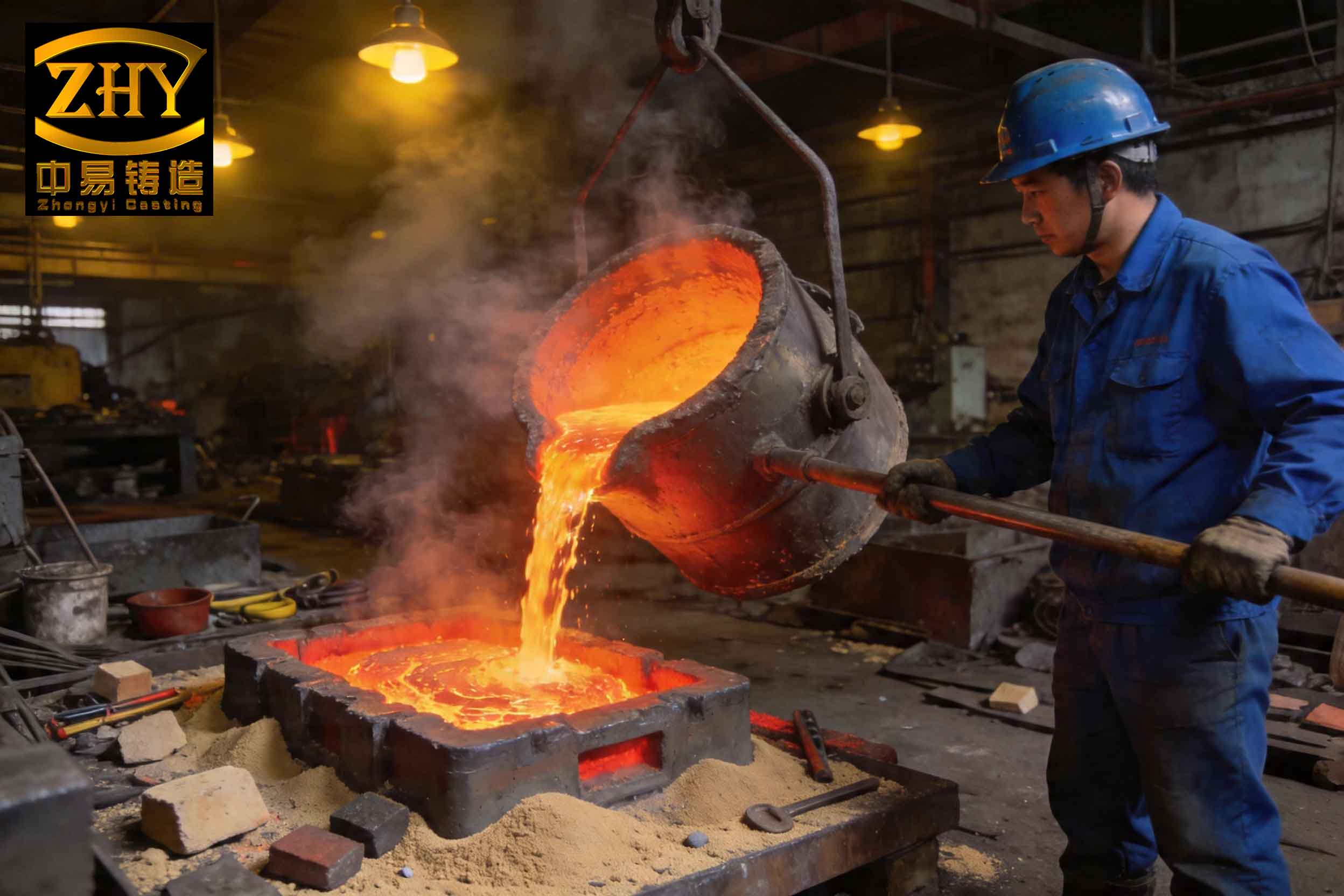
The table below summarizes the key characteristics of the observed defect:
| Feature | Observation |
|---|---|
| Location | Transverse bolt bosses on main bearing cap seats |
| Macroscopic Appearance | Non-metallic, brittle discontinuity on machined surface |
| Primary Elements (EDS) | O, Si, Al, (K, Na traces) |
| Probable Composition | Complex oxides (SiO₂, Al₂O₃) and silicates |
| Impact | Prevents proper assembly, requires costly repair or scrap |
2. Root Cause Analysis: A Multi-Faceted Problem
The investigation into the root cause of this pervasive slag inclusion defect focused on three interconnected areas: metal treatment practice, gating system design, and the specific geometry of the casting.
2.1 Metal Treatment and Slag Formation
The original melting and treatment practice was identified as a primary contributor to poor metal cleanliness. The charge makeup for the CW250 iron is shown below:
| Charge Material | Percentage (%) |
|---|---|
| Pig Iron | 0 – 10 |
| Steel Scrap | 40 – 50 |
| Returns | 30 – 50 |
The target base composition before treatment was within the following ranges:
| Element | Target % |
|---|---|
| C | 3.0 – 3.5 |
| Si | 1.3 – 1.8 |
| Mn | 0.5 – 1.5 |
| S | 0.06 – 0.12 |
| P | ≤ 0.1 |
The problematic practice was the addition of all treatment materials—including primary inoculant (Si-Ba), rare earth silicide, electrolytic copper, ferrochrome, and ferromolybdenum—to the bottom of the pouring ladle before tap. The iron was tapped from the furnace at 1480-1500°C. This method created several issues conducive to slag inclusion formation:
- Undissolved Alloys: Ferromolybdenum (FeMo), for instance, has a very high melting point, typically in the range of $$1750^\circ C – 1980^\circ C$$. At the tapping temperature, it cannot fully dissolve. These undissolved, high-density particles can be carried into the mold cavity, acting as direct nuclei for or components of a slag inclusion.
- Poor Inoculant Efficiency and Reaction Products: Adding large amounts of inoculant to the ladle bottom leads to uneven dissolution and premature reaction with the atmosphere, forming oxides. The reaction can be simplified as:
$$ \text{Si (from inoculant)} + O_2 \rightarrow SiO_2 \text{ (slag)} $$
This creates a primary source of slag before the metal even enters the mold. - Inadequate Slag Removal: The practice of “dumping” treatment materials into the ladle generates a significant amount of immediate slag, which must be thoroughly removed before pouring. Inadequate skimming would guarantee the transfer of this slag into the casting.
2.2 Gating System Design Limitations
The casting was produced using a horizontal pouring layout. The gating system was a pressurized (choke-at-bottom) design, intended to promote a smooth, non-turbulent fill. However, a critical flaw was the absence of any filtration. While a properly designed pressurized system has some slag-trapping capability in the sprue well and horizontal runners, its efficiency is limited against fine, suspended, or late-forming slag. Without a ceramic filter, the system provided no physical barrier to prevent slag particles from entering the mold cavity. The flow velocity in such a system can be estimated using Bernoulli’s principle. The velocity at the sprue base (choke) is:
$$ v = \sqrt{2gh} $$
where \( g \) is acceleration due to gravity and \( h \) is the effective sprue height. High velocity can exacerbate the entrainment of any slag present at the metal front.
2.3 Unfavorable Casting Geometry
The specific location of the defect was not coincidental. The transverse bolt bosses are protrusions on the upper surface of the casting cavity during horizontal pouring. Analyzing the mold filling pattern, these bosses act as “last-to-fill” or “hot-spot” areas. During filling, any slag with a lower density than the iron (which is almost always the case) will float to the top of the metal stream. As the metal rises to fill these upper bosses, it can trap and concentrate the buoyant slag at these highest points. Effectively, the boss geometry functioned as an unintended “slag collection pocket.” The tendency for slag to float can be described by Stokes’ law for the terminal velocity of a sphere in a fluid:
$$ v_t = \frac{2}{9} \frac{(\rho_f – \rho_s) g r^2}{\eta} $$
where:
\( v_t \) = terminal velocity (rising speed),
\( \rho_f \) = density of molten iron,
\( \rho_s \) = density of slag,
\( g \) = gravitational acceleration,
\( r \) = effective radius of the slag particle,
\( \eta \) = dynamic viscosity of molten iron.
Since \( \rho_s << \rho_f \), the velocity is positive (upward), driving slag particles to the upper surfaces of the cavity.
3. Comprehensive Corrective Actions
The solution required a multi-pronged attack targeting each root cause to eliminate the slag inclusion defect definitively.
3.1 Optimization of Melting and Treatment Practice
The metal treatment process was completely revised to maximize cleanliness and assimilation.
- Dedicated Melts: A strict policy was instituted to melt CW250 iron from dedicated charges. The practice of adjusting leftover ductile or compacted graphite iron base iron to gray iron specifications was prohibited to avoid contamination from residual inoculants or alloys.
- Furnace Alloying:
- All high-melting-point alloys (Ferrochrome, Ferromolybdenum) were added directly to the furnace.
- The furnace temperature was raised to a minimum of $$1520^\circ C$$ and held for a sufficient time (e.g., 5-10 minutes) to ensure complete dissolution of these alloys before tap. The dissolution rate can be modeled as a function of temperature and time. While simplified, the process follows an Arrhenius-type relationship where the rate constant \( k \) increases exponentially with temperature:
$$ k = A e^{-E_a/(RT)} $$
where \( E_a \) is the activation energy for dissolution, \( R \) is the gas constant, and \( T \) is the absolute temperature. The hold at 1520°C significantly increased \( k \), ensuring dissolution.
- Ladle Inoculation: The primary Si-Ba inoculant was removed from the ladle bottom addition. Instead, it was added during the tap using a controlled stream inoculation method. This ensured rapid dissolution and homogenization in the turbulent ladle stream, minimizing contact with air and the formation of primary \( SiO_2 \) slag.
- Enhanced Slag Removal: The number and thoroughness of slag skimming operations after tap were increased. A second skimming was performed just before pouring to ensure a clean metal surface.
3.2 Modification of the Gating System
Adding a filter to the existing gating system was essential. Since the horizontal runner layout was too compact for a standard filter placement, the solution was to integrate a ceramic foam filter at the interface between the pouring basin/sprue cup and the downsprue. The key design consideration was to ensure the filter did not become the flow-limiting choke, which could slow pouring and create other defects. The required filter area \( A_f \) was calculated based on the choke (sprue exit) area \( A_c \) and typical recommended filtration velocities \( v_f \) (≈ 0.5 – 1.0 kg/cm²/s).
Let:
$$ A_c = \pi (d_c/2)^2 $$
where \( d_c \) is the sprue exit diameter.
The mass flow rate \( \dot{m} \) is:
$$ \dot{m} = \rho \cdot A_c \cdot v_c $$
where \( v_c = \sqrt{2gh} \).
The required filter area is then:
$$ A_f \ge \frac{\dot{m}}{\rho \cdot v_f} = \frac{A_c \cdot v_c}{v_f} $$
Since \( v_c > v_f \), it follows that \( A_f > A_c \). A filter was selected with a cross-sectional area approximately 1.5 to 2 times the sprue exit area, maintaining the pressurized system’s characteristics while providing an effective physical barrier to slag inclusion particles. The modified design is conceptually shown below:
| Component | Original Design | Modified Design |
|---|---|---|
| Sprue Cup / Basin | Open connection to sprue | Houses ceramic filter plate |
| Filter | None | Ceramic foam, area > 1.5*A_sprue |
| Primary Function | Flow control only | Flow control + Slag filtration |
| Slag Trapping Efficacy | Low (only gravity/velocity effects) | Very High (mechanical interception) |
3.3 Compensating for Unavoidable Geometry
Recognizing that the bolt boss geometry would always be a potential risk area for collecting any residual slag, a simple but effective manufacturing tolerance was increased: the machining allowance on these specific bosses. By adding an extra 1-2 mm of stock material, any minor, sub-surface slag inclusion that might still form despite the other improvements would be completely removed during the machining process, guaranteeing a sound final part.
4. Results and Production Validation
The combined corrective actions were implemented and validated over an extended production run encompassing more than twenty castings. The results were conclusive:
- Elimination of Defect: The specific slag inclusion defect on the transverse bolt bosses was completely eliminated. No rejections occurred for this cause post-implementation.
- Improved Process Stability: The changes led to overall cleaner metal, more consistent alloy recovery (especially for Mo and Cr), and more reliable inoculation. The standard deviation of key mechanical properties (tensile strength) decreased.
- Robust Solution: The solution proved to be robust, unaffected by normal batch-to-batch variations in raw materials or minor process fluctuations.
The table below contrasts the key parameters before and after the implementation of the solutions:
| Aspect | Initial Problematic State | Final Corrected State |
|---|---|---|
| Alloy Addition | Ladle bottom, post-tap | Furnace + Hold at >1520°C |
| Primary Inoculation | Ladle bottom | Controlled stream during tap |
| Metal Cleanliness | Low (High slag load) | High (Effective skimming) |
| Gating Filtration | None | Ceramic foam filter at sprue |
| Boss Machining Allowance | Standard | Increased by 1-2 mm |
| Slag Inclusion Defect Rate | High (>30%) | Zero |
5. Conclusion
The resolution of the persistent slag inclusion defect in the large CW250 cylinder block underscores fundamental principles in foundry engineering. First, the cleanliness of molten metal is the primary defense against slag inclusion. This is controlled not just by skimming, but more importantly, by the methodology of adding treatment materials. Adding high-melting-point alloys to the ladle is a high-risk practice for creating undissolved particles that become slag inclusion nuclei. Secondly, while gating system design principles are important for flow control, they cannot compensate for inherently dirty metal. The integration of an effective filtration system, correctly sized to not disrupt the intended flow dynamics, is a critical and often indispensable component for producing high-integrity castings, especially large ones. Finally, a holistic view that considers process metallurgy, gating design, and part geometry is essential for diagnosing and solving complex casting defects like slag inclusion. The synergy of furnace alloying, improved inoculation, effective filtration, and a slight design-for-manufacture adjustment provided a complete and lasting solution, transforming a chronic quality problem into a validated, reliable process.