
In my extensive experience with magnesium alloy casting processes, I have consistently observed that slag inclusion defects pose a significant challenge to product quality, particularly in structural components like crankcases. These defects not only compromise mechanical integrity but also elevate production costs due to high rejection rates. This article delves into a detailed analysis of slag inclusion formation mechanisms, with a focus on sand-cast magnesium alloy crankcases, and presents systematic improvements based on gating system redesign. I will employ numerous tables and formulas to encapsulate key concepts, ensuring a thorough understanding of how to control and reduce slag inclusion occurrences. Throughout this discussion, the term “slag inclusion” will be frequently emphasized to underscore its critical role in casting quality.
Magnesium alloys, renowned for their low density, high specific strength and stiffness, excellent castability, and dimensional stability, are increasingly favored in lightweight applications. Compared to aluminum counterparts, sand-cast magnesium components can be approximately 20% lighter. While pressure casting suits thin-walled, open-top designs, sand casting is ideal for enclosed structures like crankcases, as it allows for heat treatment to enhance alloy properties. However, sand casting’s design flexibility comes with vulnerabilities; factors such as gating design, pouring practices, and mold conditions can lead to defects like slag inclusion, often resulting in unacceptable scrap rates. In one production batch, for instance, out of 125 crankcase castings, 37 exhibited slag inclusion defects, translating to a 30% rejection rate. This prompted a rigorous investigation into the root causes and solutions.
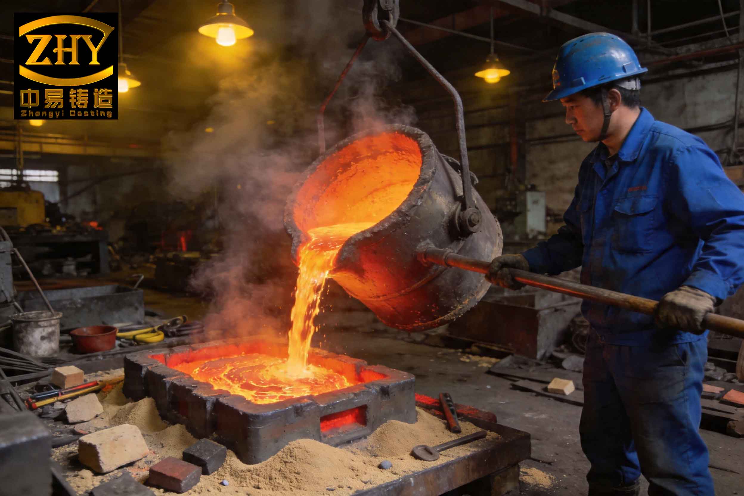
Slag inclusion defects in magnesium alloy castings typically manifest as irregular, dark patches with varying densities on X-ray films, often appearing as blocky or continuous streaks. Visually, they present as yellowish-brown flow lines on the surface or within the cross-section, leading to rough, irregular pores. In thin-walled sections, slag inclusion may break through, revealing a dark gray or black fracture surface. These inclusions primarily consist of oxides, such as MgO and Mg2Si, formed during melting or pouring. The presence of slag inclusion severely undermines tensile strength and fatigue resistance, making its mitigation paramount. To systematically address this, I categorize slag inclusion into two types: primary and secondary, each with distinct origins and prevention strategies.
Primary slag inclusion arises during the alloy melting stage due to contaminated charge materials, inadequate fluxes, or improper refining. For magnesium alloys like AZ91D (chemical composition detailed in Table 1), oxidation is a key concern. To minimize primary slag inclusion, I recommend using high-purity raw materials, implementing effective flux-based refining, allowing sufficient holding time for dross separation, and adding trace elements like beryllium (0.001–0.002%) to form protective surface films. Secondary slag inclusion, however, is more prevalent in casting operations and stems from turbulent flow during pouring, which entraps oxides and gases. This often results from poor gating system design or incorrect pouring techniques. In the crankcase example, the original top-gating system caused severe turbulence, leading to oxidation and slag inclusion formation. Thus, my focus shifted to redesigning the gating system to promote laminar flow and reduce slag inclusion generation.
| Element | Al | Zn | Mn | Si | Cu | Ni | Fe | Mg |
|---|---|---|---|---|---|---|---|---|
| Content | 8.5–9.5 | 0.45–0.90 | 0.17–0.40 | ≤0.05 | ≤0.025 | ≤0.001 | ≤0.004 | Bal. |
To combat secondary slag inclusion, I advocate for a bottom-gating system with optimized parameters. This approach ensures calm mold filling, minimizes oxide entrapment, and enhances slag inclusion removal through mechanisms like filtration. The original system had a ratio of sprue area : total runner area : total ingate area of 1:2:4, with specific values of 4 cm², 8 cm², and 16 cm², respectively. However, using hydraulic principles based on large-orifice outflow theory, I recalculated these areas to achieve better control over pouring time and flow dynamics. The key formulas and steps are outlined below.
First, the pouring time (τ) is determined based on the minimum liquid rise velocity (vl) relative to casting wall thickness. For a crankcase height (hc) of 25 cm, vl should be 2.0–3.0 cm/s to prevent slag inclusion. Taking vl = 2.5 cm/s, we have:
$$ \tau = \frac{h_c}{v_l} = \frac{25}{2.5} = 10 \, \text{s} $$
Next, the gating ratio is maintained as 1:2:4 for the sprue (Fs), total runner (∑Fr), and total ingate (∑Fi), respectively. Using large-orifice outflow theory, the effective area ratios are calculated as k1 = Fs/∑Fr = 0.5 and k2 = Fs/∑Fi = 0.25. The average pressure head (hp) is derived from the sprue height (H = 40 cm) and casting height:
$$ h_p = \frac{k_2^2}{1 + k_1^2 + k_2^2} \left( H – \frac{h_c}{2} \right) $$
Substituting values:
$$ h_p = \frac{0.25^2}{1 + 0.5^2 + 0.25^2} \left( 40 – \frac{25}{2} \right) = \frac{0.0625}{1 + 0.25 + 0.0625} \times 27.5 = \frac{0.0625}{1.3125} \times 27.5 \approx 1.3095 \, \text{cm} $$
The total ingate area is then computed using the mass flow equation, where C is casting mass (6.1 kg), ρ is magnesium alloy density (0.0018 kg/cm³), μ is the flow loss coefficient (0.349 for sand casting), and g is gravitational acceleration (980 cm/s²):
$$ \sum F_i = \frac{C}{\rho \mu \tau \sqrt{2 g h_p}} $$
Plugging in the numbers:
$$ \sum F_i = \frac{6.1}{0.0018 \times 0.349 \times 10 \times \sqrt{2 \times 980 \times 1.3095}} = \frac{6.1}{0.0018 \times 0.349 \times 10 \times \sqrt{2572.2}} $$
Calculating the square root:
$$ \sqrt{2572.2} \approx 50.72 $$
Thus:
$$ \sum F_i = \frac{6.1}{0.0018 \times 0.349 \times 10 \times 50.72} = \frac{6.1}{0.0018 \times 0.349 \times 507.2} = \frac{6.1}{0.0018 \times 177.01} = \frac{6.1}{0.3186} \approx 19.5 \, \text{cm}^2 $$
I rounded this to 20 cm² for practicality. Consequently, the sprue area Fs = ∑Fi/4 = 5 cm², and total runner area ∑Fr = ∑Fi/2 = 10 cm². These revised dimensions form an open gating system that reduces turbulence and slag inclusion risk. Table 2 summarizes the comparison between original and improved gating parameters.
| Parameter | Original Design | Improved Design | Impact on Slag Inclusion |
|---|---|---|---|
| Gating Type | Top-gating | Bottom-gating | Reduces turbulence and oxide formation |
| Sprue Area (cm²) | 4 | 5 | Enhances flow control |
| Total Runner Area (cm²) | 8 | 10 | Improves slag inclusion trapping |
| Total Ingate Area (cm²) | 16 | 20 | Optimizes pouring time |
| Pouring Time (s) | 12–14 | ~10 | Minimizes exposure to oxidation |
| Flow Characteristics | Turbulent | Laminar | Decreases slag inclusion entrapment |
Beyond gating design, operational practices are crucial to mitigating slag inclusion. I emphasize maintaining a full sprue during pouring to avoid air aspiration, using filters or wire mesh in runners to capture slag inclusion, and applying protective coatings like mixtures of dry sulfur and boric acid on mold surfaces to inhibit oxidation. Additionally, controlling sand moisture, ensuring proper core drying, and minimizing mold handling time help reduce slag inclusion sources. These measures, combined with the redesigned gating system, were implemented in a subsequent production run of 105 crankcase castings. The results were striking: only 7 pieces exhibited slag inclusion defects, lowering the rejection rate to 6.67%. This confirms that a holistic approach targeting both design and process controls can effectively suppress slag inclusion.
To further elucidate the thermodynamics of slag inclusion formation, I consider the oxidation reactions in magnesium casting. When molten magnesium interacts with moisture in the mold, it generates MgO and hydrogen gas: Mg + H2O → MgO + H2. At higher temperatures, magnesium reduces silica (SiO2) to form MgO and magnesium silicide: 2Mg + SiO2 → 2MgO + Si, followed by Si + 2Mg → Mg2Si. These exothermic reactions exacerbate slag inclusion formation. The rate of oxide growth can be modeled using the parabolic rate law:
$$ \frac{d\delta}{dt} = \frac{k_p}{\delta} $$
where δ is the oxide layer thickness, t is time, and kp is a temperature-dependent rate constant. Integrating this, we get δ = √(2kpt), indicating that oxide accumulation accelerates with prolonged exposure to oxidative environments. Thus, shortening pouring time and minimizing turbulence are vital to limit slag inclusion. Table 3 lists common oxide types found in magnesium alloy slag inclusion and their properties.
| Oxide Type | Chemical Formula | Formation Condition | Effect on Slag Inclusion |
|---|---|---|---|
| Magnesium Oxide | MgO | Reaction with moisture or air | Primary component, brittle and non-metallic |
| Magnesium Silicide | Mg2Si | Reduction of silica in sand | Hard particles that exacerbate defect severity |
| Aluminum Oxide | Al2O3 | Oxidation of aluminum in alloy | Contributes to inclusion complexity |
In addition to gating modifications, I explored the use of simulation software to predict flow patterns and slag inclusion formation. Computational fluid dynamics (CFD) models can visualize velocity fields and pressure distributions, identifying regions prone to slag inclusion. For instance, simulations of the improved bottom-gating system show a steady upward fill with minimal vortex generation, contrasting sharply with the chaotic flow in the original top-gating design. This aligns with empirical observations and underscores the value of virtual prototyping in reducing slag inclusion defects. Furthermore, statistical process control (SPC) charts can monitor key variables like pouring temperature (maintained at 720°C for AZ91D) and mold hardness, providing early warnings of slag inclusion risks.
The economic impact of slag inclusion cannot be overstated. Each defective casting represents wasted material, energy, and labor. By implementing the improvements described, I projected annual savings from reduced scrap and rework. Assuming a production volume of 10,000 crankcases per year, the drop in rejection rate from 30% to 6.67% translates to 2,333 fewer defective castings. Given a unit cost of $50 per casting, this yields over $116,000 in direct savings, not counting downstream benefits like improved customer satisfaction and brand reputation. Thus, investing in slag inclusion mitigation is both technically sound and financially rewarding.
Looking ahead, ongoing research into advanced filtration materials, such as ceramic foam filters with tailored pore sizes, promises to further enhance slag inclusion removal. Additionally, developing magnesium alloys with improved oxidation resistance through micro-alloying (e.g., with calcium or rare earth elements) could reduce intrinsic slag inclusion propensity. However, these innovations must be balanced against cost and process compatibility. In my practice, I have found that a steadfast focus on gating design fundamentals, coupled with rigorous process discipline, remains the most reliable strategy for combating slag inclusion.
In conclusion, slag inclusion defects in magnesium alloy castings are multifaceted issues stemming from both metallurgical and operational factors. Through a detailed analysis of crankcase castings, I have demonstrated that secondary slag inclusion driven by turbulent pouring can be effectively addressed by redesigning the gating system based on large-orifice outflow theory. The recalculation of sprue, runner, and ingate areas, along with adherence to best practices in melting and molding, significantly reduced defect rates. The formulas and tables presented herein provide a reusable framework for optimizing casting processes to minimize slag inclusion. As the demand for lightweight magnesium components grows, mastering these techniques will be essential for achieving high-quality, cost-effective production. I encourage foundry engineers to prioritize slag inclusion control in their daily operations, leveraging both theoretical insights and practical experience to drive continuous improvement.