
In my extensive experience with ductile iron production, the formation of slag inclusions, often referred to as dross or slag defects, represents one of the most persistent and challenging quality issues. This defect fundamentally stems from the very process that gives ductile iron its unique properties: the magnesium treatment. Understanding the genesis, morphology, and, most importantly, the prevention strategies for these inclusions is critical for producing high-integrity castings.
The Genesis of Slag Inclusions
The formation of slag inclusions is an inherent byproduct of the nodularization process. When molten iron is treated with magnesium (Mg) to induce the precipitation of spheroidal graphite, a series of vigorous reactions occur. Magnesium possesses a high affinity for both oxygen and sulfur present in the melt. Consequently, primary reaction products are formed immediately during treatment:
- Magnesium Oxide (MgO): $$ \text{Mg} + \frac{1}{2}\text{O}_2 \rightarrow \text{MgO} $$
- Magnesium Sulfide (MgS): $$ \text{Mg} + \text{S} \rightarrow \text{MgS} $$
These compounds, being less dense than the iron melt, tend to float to the surface, forming a slag layer. However, the problem does not end at treatment. The residual magnesium in the treated iron remains highly reactive. During holding, transfer, and crucially during pouring, this residual magnesium can continue to oxidize through contact with air, leading to the secondary formation of oxides: $$ \text{Mg} + \frac{1}{2}\text{O}_2 \ (\text{from air}) \rightarrow \text{MgO} $$
If this slag—comprising primary and secondary reaction products—is not effectively separated from the metal stream, it becomes entrapped within the mold cavity. Upon solidification, these non-metallic inclusions manifest as the defect we term slag inclusions. Their composition is complex, typically involving a mixture of MgO, MgS, silicates, and often entrapped sand particles or de-oxidation products containing elements like silicon, manganese, and aluminum.
Identification and Morphology of Slag Inclusions
Identifying slag inclusions requires a combination of visual inspection, non-destructive testing, and finally, metallographic analysis. The defect rarely reveals itself on an as-cast surface unless severe. Common locations are predictable based on density and flow dynamics:
| Location | Typical Appearance | Notes |
|---|---|---|
| Upper surfaces, just beneath the skin | Wrinkles, folds, or rough patches | Caused by slag films floating to the top. |
| Upper surfaces of cores (downhand surfaces) | Dark, non-metallic streaks or patches | Slag carried over the top of the flowing metal settles here. |
| Corners and junction points | Localized surface imperfections | Turbulence in these areas can trap slag. |
| Vertical walls | Less common, but possible as streaks | Indicates severe turbulence or excessive slag carryover. |
After shot blasting or machining, these areas appear as dark, non-metallic voids lacking metallic luster. They can range from large, continuous films to dispersed, spot-like formations. In severe cases, slag inclusions are associated with gas pores, forming compound defects. Subsurface inclusions, only revealed after machining, often consist of dispersed graphite clusters and micro-inclusions. For definitive analysis, a sample must be sectioned from the defect zone for microscopic examination and elemental analysis (e.g., using Energy Dispersive Spectroscopy – EDS). Sulfur printing is a classic macro-etch technique that can vividly reveal the presence of sulfide-rich slag inclusions.
A Systematic Approach to Preventing Slag Inclusions
The prevention strategy for slag inclusions is built on a three-pillar approach: Minimize the generation of slag, Separate slag from the metal before it enters the mold, and Suppress further slag formation within the mold itself. This requires coordinated control across the entire production chain.
1. Melt Preparation and Chemistry Control
The foundation for clean metal is laid at the melting stage. The goal is to present the lowest possible burden of reactive elements to the magnesium treatment process.
- Sulfur Control: The single most important factor. A low base sulfur content reduces the amount of Mg required for effective nodularization, thereby reducing the volume of MgS formed. The relationship can be simplified as: $$ \text{Mg added} \propto \text{Base S\%} $$ Aiming for base sulfur levels below 0.015% is a common industry target.
- Carbon Equivalent (CE) Control: While a high CE improves fluidity and castability, an excessively high CE promotes graphite flotation. These buoyant graphite clusters can act as carriers for slag particles, dragging them to upper surfaces and creating a specific type of inclusion defect. The CE should be optimized, not maximized.
2. Optimization of Nodularization and Inoculation
This is the critical phase where most slag inclusions originate. Precise control is paramount.
| Parameter | Target / Action | Rationale |
|---|---|---|
| Residual Magnesium | Minimize to level ensuring nodularity | Reduces raw material for MgO/MgS formation post-treatment. |
| Residual Rare Earth (RE) | Maintain sufficient level | RE elements help form a lower-melting-point, less tenacious surface slag that agglomerates and separates more easily. |
| Treatment Temperature | Avoid excessively low temperatures | Higher temperature improves slag mobility and buoyancy for removal. |
| Use of Fluxes (e.g., NaCl) | Add with nodularizing alloy | Fluxes react with MgO/MgS to form a low-viscosity slag that coalesces and rises rapidly. |
| Post-Treatment Holding | Allow for 2-4 minutes of quiet holding | Provides essential time for slag particles to float to the surface. |
| Slag Removal & Covering | Thoroughly skim, then cover with insulating/barrier cover (e.g., exothermic) | Removes generated slag and protects melt surface from re-oxidation. |
3. Molding and Core Materials
The mold environment should be neutral or reducing to prevent oxidation of the flowing metal. This is achieved by ensuring adequate carbonaceous materials (e.g., seacoal, cellulose) in the green sand system, which generate a protective gas curtain. Crucially, high-sulfur coal should be avoided, as it can contribute to sulfur pickup and exacerbate slag inclusions formation.
4. Gating System Design Philosophy
The gating system must be designed as an active slag trap, not just a passive channel. Key principles include:
- Slag Traps: Use well-designed pour cups with dams and/or whirl gates (spinner gates). A whirl gate uses centrifugal force to separate slag, described by the force balance where the denser metal is thrown outward: $$ F_c = \frac{m v^2}{r} $$ where slag, being less dense, remains near the vortex center.
- Laminar Flow: Design sprue, runner, and ingate proportions (e.g., using a pressurized system) to maintain a full, non-turbulent flow. Avoid abrupt changes in direction or cross-section.
- Strategic Placement: Gate into the mold cavity at the lowest practical point and use horizontal runners in the drag with ingates rising into the cope to trap slag in the runner.
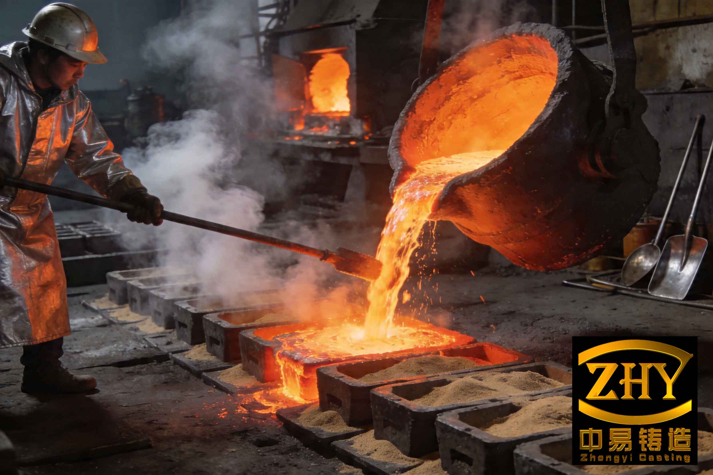
5. Pouring Practice and Ladle Management
The final line of defense against slag inclusions is meticulous pouring practice.
| Factor | Guideline | Impact on Slag |
|---|---|---|
| Pouring Temperature | As high as practically possible (e.g., >1380°C) | Higher temperature drastically reduces melt surface tension and slag viscosity, allowing entrapped slag to float out more readily before solidification. Below a critical temperature (e.g., ~1350°C), the risk escalates. |
| Ladle Lining | Use basic or neutral refractories; maintain smooth, clean lining | Prevents chemical erosion of the lining which generates new slag, and removes ledges that can trap old slag. |
| Pouring Rate & Steadiness | Pour quickly to maintain a full sprue, but steadily without interruption | A full sprue creates a choke, preventing slag from being drawn in. Turbulence from erratic pouring entraps slag. |
| Metal Transfer | Minimize height of fall, use tapered sprue | Reduces re-oxidation and air entrainment during the pour. |
In conclusion, combating slag inclusions in ductile iron is not about a single silver bullet, but the rigorous application of a holistic control strategy. From charge selection to the final pour, every step must be managed with the goal of minimizing the creation and entrapment of these non-metallic compounds. The interdependence of chemistry, process parameters, and engineering design means that success is found in consistency and attention to detail across the entire foundry floor. By implementing the measures outlined—controlling base sulfur, optimizing treatment, designing effective gating, and maintaining disciplined pouring practices—the incidence of these costly defects can be reduced to minimal levels, ensuring the production of high-quality, reliable ductile iron castings.