
In the field of metal casting, the presence of slag inclusions remains a critical issue that significantly compromises the integrity and performance of cast components. As a researcher focused on improving casting quality, I have delved into the intricate relationship between gating system design and the behavior of slag inclusions during gravity casting processes. This study aims to provide a comprehensive analysis of how various gating system configurations influence the entrapment and distribution of slag inclusions, with the ultimate goal of minimizing these defects. Through numerical simulations and experimental validations, I explore the dynamics of slag particle movement, the efficacy of different gating designs in slag removal, and the underlying mechanisms that govern slag inclusion behavior. The findings presented here are intended to offer practical insights for optimizing gating systems in industrial applications, thereby enhancing the fatigue resistance and overall reliability of castings.
Slag inclusions, which are non-metallic particles entrapped within the casting matrix, often originate from refractory materials, mold erosion, or reaction products during melting and pouring. These inclusions act as stress concentrators, initiating fatigue cracks and leading to premature failure under cyclic loading. In aluminum alloy castings, such as ZL101, the density of slag particles is close to that of the molten metal, making their separation challenging. The gating system, which controls the flow of molten metal into the mold cavity, plays a pivotal role in mitigating slag inclusions by promoting slag particle flotation and trapping them before they enter the casting. However, designing an effective gating system requires a deep understanding of fluid dynamics and particle behavior. In this work, I employ a dispersed phase particle model to simulate the motion of slag inclusions, validating the model with experimental data. Four distinct gating system designs are evaluated for their slag removal efficiency, and the results are analyzed using statistical methods and physical principles. By integrating simulations with practical considerations, I seek to establish guidelines for gating system optimization that reduce slag inclusion defects.
The importance of addressing slag inclusions cannot be overstated. In industries such as automotive and aerospace, where cast components are subjected to high stresses, even minor inclusions can lead to catastrophic failures. Traditional methods for assessing gating system performance, such as sampling and physical modeling, are often labor-intensive and lack precision. Numerical simulation, on the other hand, offers a robust alternative by allowing detailed tracking of slag particles throughout the filling process. In this study, I leverage advanced computational fluid dynamics (CFD) techniques to model the two-phase flow of molten aluminum and slag particles. The dispersed phase model treats slag particles as discrete entities influenced by drag, buoyancy, and turbulence forces, enabling accurate prediction of their trajectories. This approach not only saves time and resources but also provides insights that are difficult to obtain experimentally.
To set the stage for this investigation, I begin by reviewing the fundamental principles of gating system design. Gating systems typically consist of a pouring basin, sprue, runner, and ingates, each component contributing to the control of metal flow. The design parameters, such as cross-sectional areas, geometry, and the inclusion of slag traps, directly impact the velocity and turbulence of the molten metal. For instance, a semi-closed gating system, where the cross-sectional area of the runner is larger than that of the ingates, reduces flow velocity and promotes laminar flow, thereby enhancing slag flotation. Conversely, an open gating system may lead to high velocities that carry slag particles into the mold cavity. Additionally, features like centrifugal scum risers or trapezoidal slag collectors can be incorporated to trap slag particles. In this work, I design four gating systems based on these principles, each with unique characteristics, to evaluate their effectiveness in reducing slag inclusions.
The core of this study revolves around the simulation of slag inclusion behavior using the dispersed phase model. The casting geometry chosen is a standard stress frame, which features varying section thicknesses and corners that influence flow patterns. This geometry is representative of complex castings where slag inclusions are prone to accumulate. The simulation parameters include the properties of ZL101 aluminum alloy (density: 2420 kg/m³, pouring temperature: 670°C) and slag particles (density: 1850 kg/m³, diameter: 0.60 mm). A total of 20,000 slag particles are introduced into the system to mimic the dispersion of inclusions in the molten metal. The filling process is simulated under gravity pouring conditions, with a pouring velocity of 0.35 m/s. The governing equations for fluid flow and particle motion are solved using finite element methods, and the results are visualized to show the distribution of slag particles at different stages of filling.
Before delving into the gating system comparisons, I validate the simulation model through experimental trials. The experimental setup replicates the simulation conditions, using carefully selected sand particles to simulate slag inclusions. After pouring, the castings are sectioned at key locations, and the distribution of particles is compared with the simulation predictions. The close agreement between the experimental and simulated results confirms the reliability of the dispersed phase model. This validation step is crucial, as it ensures that the subsequent analyses are grounded in realistic physics.
With the validated model in hand, I proceed to design the four gating systems. The details of each design are summarized in Table 1, which includes the gating system type, slag trap configurations, and schematic representations. The first system is an open vertical branching design with two slag risers. The second is a semi-closed flat-straight runner system with two slag risers. The third system incorporates trapezoidal slag collectors along the runner, along with three slag risers. The fourth system features a semi-closed runner with a centrifugal scum riser and four slag risers. All systems are designed to maintain the same total volume and pouring conditions to ensure fair comparisons.
| Design | Gating System Type | Slag Trap Configuration | Key Dimensions (mm) |
|---|---|---|---|
| Design 1 | Open Vertical Branching | 2 slag risers (diameter: 24, height: 80) | Sprue: 20×20, Runner: 15×15, Ingates: 10×10 |
| Design 2 | Semi-Closed Flat-Straight Runner | 2 slag risers (diameter: 24, height: 80) | Sprue: 18×18, Runner: 25×15, Ingates: 12×10 |
| Design 3 | Semi-Closed with Trapezoidal Slag Collectors | 3 slag risers (diameter: 24, height: 80) | Sprue: 18×18, Runner: 30×15 with collectors, Ingates: 12×10 |
| Design 4 | Semi-Closed with Centrifugal Scum Riser | 4 slag risers (diameter: 24, height: 80) | Sprue: 18×18, Runner: 35×15 with centrifugal riser, Ingates: 12×10 |
The simulation results for each gating system are analyzed in terms of slag particle distribution. Figure 1 illustrates the filling process for Design 2, showing how slag inclusions move with the molten metal. Initially, during early filling stages, the slag particles are dragged by the high-velocity flow, but as the runner fills, the velocity decreases, allowing particles to float upward. This behavior is critical for understanding slag inclusion dynamics. To quantify the performance, I use a custom program written in Visual Basic to count the number of slag particles that enter the casting versus those trapped in the gating system or risers. The key metrics are defined as follows: slag removal efficiency $K_1$, single riser collection rate $K_2$, and casting slag inclusion rate $K_3$. These are calculated using the formulas:
$$ K_1 = \frac{N_0 – N_1}{N_0} \times 100\% $$
$$ K_2 = \frac{N_2}{X \cdot N_0} \times 100\% $$
$$ K_3 = \frac{N_1 – N_2}{N_0} \times 100\% $$
where $N_0$ is the total number of slag particles (20,000), $N_1$ is the number of particles passing through the ingates, $N_2$ is the number of particles collected in slag risers, and $X$ is the number of slag risers. The results for the four designs are compiled in Table 2, based on three simulation runs for each design to ensure statistical reliability.
| Design | Slag Removal Efficiency $K_1$ (%) | Single Riser Collection Rate $K_2$ (%) | Casting Slag Inclusion Rate $K_3$ (%) |
|---|---|---|---|
| Design 1 | 24.0 ± 2.1 | 11.6 ± 1.5 | 52.8 ± 3.0 |
| Design 2 | 76.5 ± 3.2 | 4.8 ± 0.9 | 13.9 ± 2.1 |
| Design 3 | 84.3 ± 2.8 | 2.5 ± 0.7 | 8.2 ± 1.8 |
| Design 4 | 85.1 ± 3.0 | 2.4 ± 0.6 | 5.3 ± 1.5 |
From Table 2, it is evident that Design 4, the semi-closed system with a centrifugal scum riser, performs best, with the highest slag removal efficiency and the lowest casting slag inclusion rate. Design 1, the open vertical branching system, shows poor performance, with over half of the slag particles ending up in the casting. This highlights the importance of gating system geometry in controlling slag inclusions. The improved performance of semi-closed systems can be attributed to the reduced flow velocity in the runner, which prolongs the residence time of slag particles and enhances their buoyancy-driven flotation. The centrifugal scum riser in Design 4 further promotes slag separation by creating a swirling motion that traps particles.
To understand the underlying physics, I analyze the forces acting on slag particles. The motion of a slag particle in molten metal is governed by the equation of motion, which can be expressed as:
$$ m_p \frac{d\mathbf{v}_p}{dt} = \mathbf{F}_d + \mathbf{F}_b + \mathbf{F}_g + \mathbf{F}_t $$
where $m_p$ is the particle mass, $\mathbf{v}_p$ is the particle velocity, $\mathbf{F}_d$ is the drag force, $\mathbf{F}_b$ is the buoyancy force, $\mathbf{F}_g$ is the gravitational force, and $\mathbf{F}_t$ represents turbulence-induced forces. The drag force is given by:
$$ \mathbf{F}_d = \frac{1}{2} C_d \rho_f A_p |\mathbf{v}_f – \mathbf{v}_p| (\mathbf{v}_f – \mathbf{v}_p) $$
where $C_d$ is the drag coefficient, $\rho_f$ is the fluid density, $A_p$ is the particle cross-sectional area, and $\mathbf{v}_f$ is the fluid velocity. The buoyancy force is $\mathbf{F}_b = \rho_f V_p \mathbf{g}$, with $V_p$ being the particle volume and $\mathbf{g}$ the gravitational acceleration. For slag particles with density close to the molten metal, the net buoyancy is small, so drag and turbulence play dominant roles. In gating systems, reducing $\mathbf{v}_f$ minimizes $\mathbf{F}_d$, allowing $\mathbf{F}_b$ to become more significant and promoting upward movement.
The simulation results also reveal the spatial distribution of slag inclusions within the casting. For instance, in Design 1, slag particles accumulate in thick sections and corners due to turbulent eddies, whereas in Design 4, most particles are trapped in the gating system. This distribution is visualized through contour plots of particle concentration, which show that slag inclusions tend to cluster in regions with low flow velocity or recirculation zones. Such insights are valuable for identifying critical areas in castings where slag inclusions are likely to occur, enabling targeted design modifications.
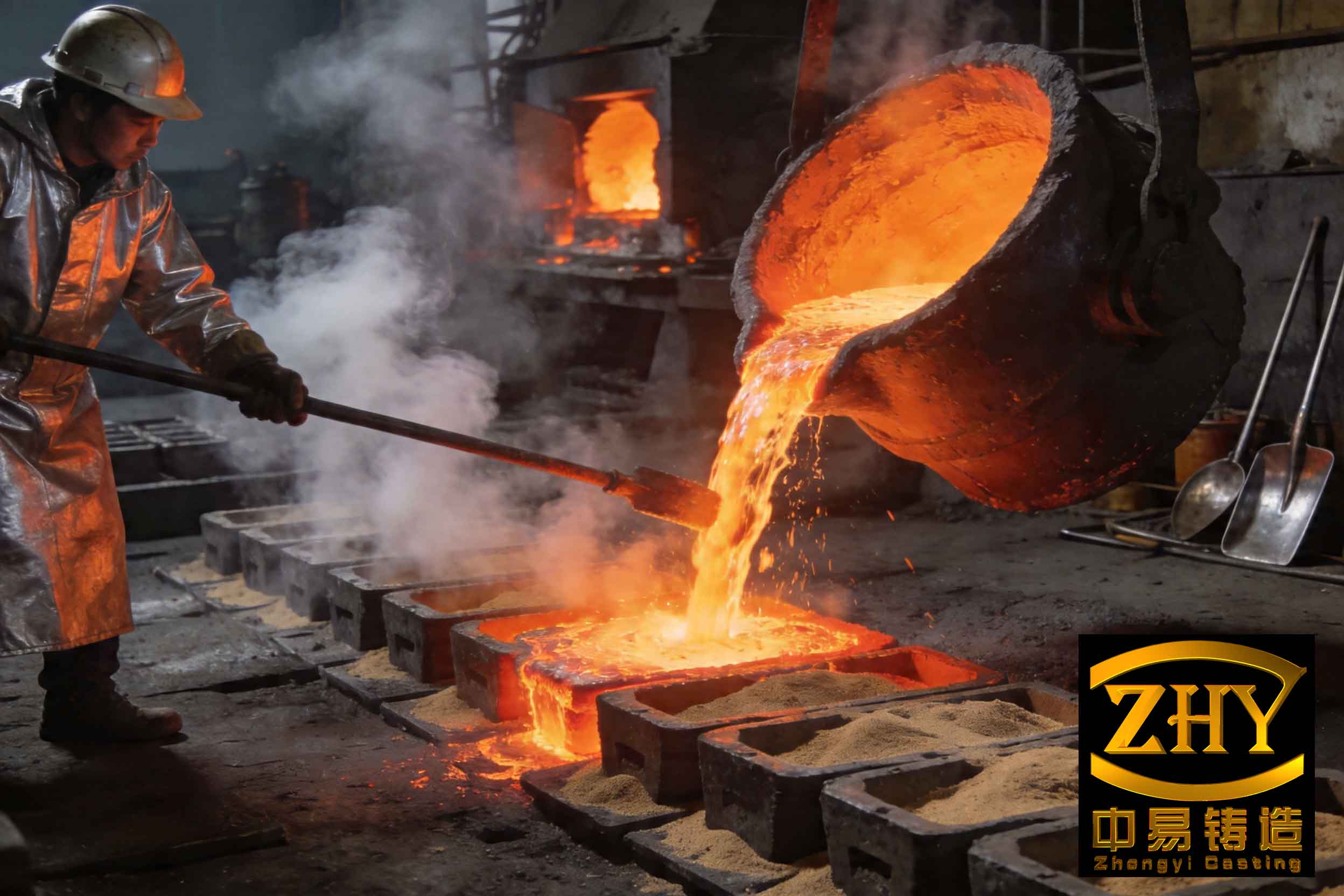
The image above illustrates typical slag inclusion defects in castings, highlighting the need for effective gating system design. In my simulations, similar defect patterns are observed when the gating system fails to remove slag particles. By comparing the simulated particle distributions with real-world defects, I can correlate design features with defect severity. For example, the centrifugal scum riser in Design 4 effectively mimics industrial slag traps that use centrifugal force to separate inclusions.
Beyond the four designs, I explore the impact of runner length and cross-sectional area on slag inclusion behavior. Using parametric studies, I vary the runner length from 100 mm to 300 mm while keeping other parameters constant. The results indicate that longer runners reduce the casting slag inclusion rate, as described by the relationship:
$$ K_3 \propto e^{-\alpha L} $$
where $L$ is the runner length and $\alpha$ is a constant dependent on flow conditions. This exponential decay suggests that extending the runner provides more time for slag particles to float out of the flow. Similarly, increasing the runner cross-sectional area decreases flow velocity, which can be quantified using the continuity equation:
$$ A_1 v_1 = A_2 v_2 $$
where $A_1$ and $v_1$ are the area and velocity at the sprue exit, and $A_2$ and $v_2$ are those in the runner. By designing a runner with a larger area, $v_2$ is reduced, lowering the drag force on slag particles. This principle is central to semi-closed gating systems, where the area ratio between runner and ingates is optimized.
Another aspect I investigate is the effect of slag particle size and density. While the main study uses particles of 0.60 mm diameter and 1850 kg/m³ density, I run additional simulations with diameters ranging from 0.10 mm to 1.00 mm and densities from 1500 kg/m³ to 2200 kg/m³. The results, summarized in Table 3, show that larger and lighter particles are easier to remove, as they experience greater buoyancy. However, even small, dense particles can be managed with proper gating design, emphasizing the versatility of the approaches discussed.
| Particle Diameter (mm) | Particle Density (kg/m³) | Slag Removal Efficiency $K_1$ (%) for Design 4 |
|---|---|---|
| 0.10 | 1850 | 72.3 ± 2.5 |
| 0.60 | 1850 | 85.1 ± 3.0 |
| 1.00 | 1850 | 91.5 ± 2.8 |
| 0.60 | 1500 | 88.7 ± 3.1 |
| 0.60 | 2200 | 81.2 ± 2.9 |
The discussion extends to practical considerations for implementing these gating systems in foundries. For aluminum alloy castings, where slag inclusions are common due to oxide formation, a semi-closed gating system with a centrifugal scum riser is recommended. The design should ensure a smooth transition between components to avoid turbulence, and slag risers should be placed near ingates to capture particles before they enter the casting. Additionally, computational tools like the dispersed phase model can be used for virtual prototyping, reducing the need for costly trial-and-error experiments.
In conclusion, this study demonstrates that gating system design profoundly influences slag inclusion behavior in castings. Through detailed simulations and analysis, I have shown that semi-closed systems with features like centrifugal scum risers significantly reduce slag inclusion defects by lowering flow velocity and promoting particle flotation. The key mechanisms involve extending the residence time of slag particles in the runner and leveraging buoyancy forces. These findings provide a foundation for optimizing gating systems in various casting applications, ultimately improving product quality and reliability. Future work could explore the integration of real-time monitoring with simulation models to further refine gating designs for specific alloys and casting geometries.
To summarize, the battle against slag inclusions is ongoing, but with advanced modeling techniques and a deep understanding of fluid-particle interactions, we can design gating systems that minimize these defects. By prioritizing factors such as runner length, cross-sectional area, and slag trap geometry, foundries can achieve higher yields and better performance in their cast components. I hope this research contributes to the ongoing efforts to enhance casting processes and reduce the prevalence of slag inclusions in industrial production.