
In my extensive experience with centrifugal ductile iron pipe production using hot mold processes, I have frequently encountered the persistent issue of slag inclusions and porosity defects at the socket D3 position, particularly in large-diameter pipes (≥1000 mm). These defects severely compromise the aesthetic appearance and mechanical strength of the final product, leading to significant quality concerns and economic losses. Through systematic investigation and process optimization, I have identified the root causes and developed effective preventive strategies. This article presents my first-person analysis, focusing on the interplay of molten metal composition, slag removal efficiency, gating system design, cooling conditions, and mechanical factors. I will employ detailed tables, mathematical formulas, and empirical data to elucidate the mechanisms and solutions, ensuring the keyword ‘slag inclusions’ is prominently featured throughout the discussion to underscore its critical role.
The socket region of a ductile iron pipe, especially the D3 face, is inherently prone to defect formation due to its greater wall thickness and complex solidification dynamics.
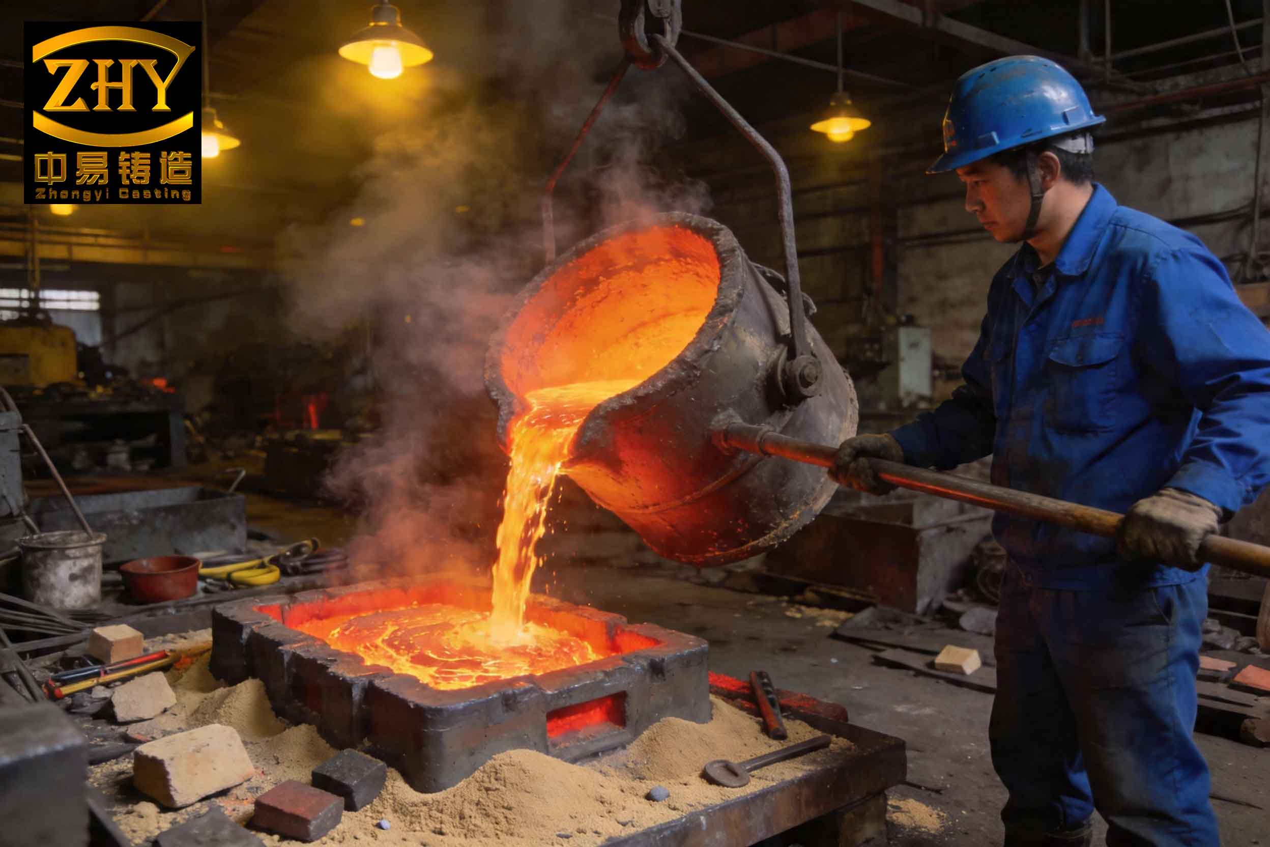
This visual representation clearly shows the typical manifestation of these defects—a rough, porous surface layer laden with non-metallic inclusions. Statistically, the defective layer at the D3 face averages 10 mm in thickness with a density ratio (actual density to theoretical density) as low as 58%. This porosity directly undermines the pressure-bearing capacity and corrosion resistance of the pipe socket, making it a critical focus for process improvement.
The fundamental principle of hot mold centrifugal casting involves pouring molten iron from a moving ladle into a high-speed rotating mold. The centrifugal force distributes the metal against the mold wall, promoting directional solidification. However, this very process facilitates the segregation of impurities. In the socket area, the slower cooling rate allows more time for slag particles, oxides, and other inclusions to migrate radially inward under centrifugal force, accumulating at the inner surface (D3 face) to form a discontinuous, weak layer. The formation mechanism can be conceptually described by a force balance on a slag particle within the rotating molten pool. The net radial force driving the particle inward is a combination of centrifugal force and buoyancy, opposed by viscous drag. For a spherical particle, the terminal radial velocity $$v_r$$ can be approximated by Stokes’ law modified for a rotating frame:
$$ v_r = \frac{2}{9} \frac{(\rho_m – \rho_s) \omega^2 r R^2}{\eta} $$
where $$\rho_m$$ is the molten iron density, $$\rho_s$$ is the slag particle density, $$\omega$$ is the angular velocity of the mold, $$r$$ is the radial position of the particle, $$R$$ is the particle radius, and $$\eta$$ is the dynamic viscosity of the iron melt. This equation highlights that slower cooling (longer solidification time $$t_f$$) allows particles more time to travel, increasing the likelihood of slag inclusions forming a continuous layer. The total distance a particle can travel is $$S = v_r \cdot t_f$$. Therefore, processes that increase $$v_r$$ or decrease $$t_f$$ are beneficial for mitigating slag inclusions.
Analysis of Influencing Factors and Experimental Validation
I conducted a series of controlled experiments to quantify the impact of various process parameters on the severity of slag inclusions and porosity at the D3 face. The response variables were the average slag layer thickness ($$L_{slag}$$) and the average density ratio ($$DR$$), defined as:
$$ DR = \frac{\rho_{actual}}{\rho_{theoretical}} \times 100\% $$
where $$\rho_{theoretical}$$ for ductile iron is approximately 7.1 g/cm³. Samples were taken from three random locations on the D3 face of each test pipe for consistency.
1. Influence of Molten Metal Composition
The chemical composition of the iron melt profoundly affects its oxidation tendency, slag formation potential, and fluidity. My focus was on residual magnesium (Mg) and titanium (Ti) content. Magnesium is highly reactive and promotes the formation of a viscous, tenacious MgO-SiO₂ surface film that can break off and become entrapped as slag inclusions. Titanium forms high-melting-point compounds like TiC, TiN, and TiS, which increase melt viscosity and hinder slag separation.
The relationship between Mg residual and slag inclusion propensity is nonlinear. While a minimum Mg level (≈0.04%) is necessary for effective nodularization, levels exceeding 0.06% dramatically increase oxidation and slag inclusion frequency. The tendency for slag film formation $$(SF)$$ can be empirically correlated as:
$$ SF \propto [Mg]_{res}^{1.5} \cdot \exp\left(\frac{-Q}{RT}\right) $$
where [Mg]_{res} is the weight percentage of residual Mg, Q is an activation energy, R is the gas constant, and T is the melt temperature in Kelvin. Similarly, Ti content above 0.050% significantly elevates melt viscosity $$\eta$$, which can be modeled using an Arrhenius-type relation with a Ti-dependent pre-exponential factor:
$$ \eta = \eta_0 (1 + \alpha [Ti]) \cdot \exp\left(\frac{E_\eta}{RT}\right) $$
where $$\eta_0$$ and $$\alpha$$ are constants, and $$E_\eta$$ is the activation energy for viscous flow. Higher viscosity reduces slag floatation velocity $$v_r$$, worsening slag inclusions. The baseline composition I established for optimal results is summarized in Table 1.
| Element | Electric Furnace Melt | Post-Nodularization Melt | Critical Limit for Slag Inclusions |
|---|---|---|---|
| Carbon (C) | 3.5 – 3.7 | 3.4 – 3.6 | >3.7 (promotes graphite flotation) |
| Silicon (Si) | 0.8 – 1.0 | 2.0 – 2.2 | <2.0 (affects fluidity) |
| Manganese (Mn) | 0.2 – 0.3 | 0.2 – 0.3 | >0.4 (promotes carbides) |
| Phosphorus (P) | 0.070 – 0.080 | < 0.070 | >0.080 (increases shrinkage) |
| Sulfur (S) | 0.020 – 0.030 | < 0.010 | >0.015 (reacts with Mg) |
| Residual Mg | – | 0.050 – 0.070 | >0.075 (severe oxidation) |
| Titanium (Ti) | < 0.050 | < 0.050 | >0.055 (viscosity spike) |
| Carbon Equivalent (CE) | 4.25 – 4.35 | 4.25 – 4.35 | – |
2. Impact of Furnace Slag Removal Practice
Effective removal of primary slag from the furnace is a crucial first step in minimizing the total inclusion load. I investigated the effects of superheating temperature and holding time in a 15-ton electric furnace. The furnace was powered at 2200 kW for heating and 500 kW for holding. The slag removal efficiency ($$E_{slag}$$) was quantified as the mass of slag removed per ton of molten iron. The results, presented in Table 2, demonstrate a clear trend: higher superheat temperature and longer holding time improve slag removal and subsequently reduce D3 face defects.
The kinetics of slag agglomeration and separation can be described by a first-order rate equation. The decrease in slag content $$C_{slag}$$ over holding time $$t$$ is:
$$ \frac{dC_{slag}}{dt} = -k (C_{slag} – C_{slag}^*) $$
where $$k$$ is a rate constant dependent on temperature $$T$$ ($$k = k_0 e^{-E_a/RT}$$), and $$C_{slag}^*$$ is the equilibrium slag content at that temperature. Integrating this gives the improvement in slag layer thickness, which correlates with the final $$L_{slag}$$. The data shows that heating to 1480°C and holding for 10 minutes is optimal, beyond which diminishing returns set in.
| Superheat Temperature (°C) | Holding Time (min) | Slag Removal (kg/ton iron) | Average Slag Layer Thickness, $$L_{slag}$$ (mm) | Average Density Ratio, $$DR$$ (%) |
|---|---|---|---|---|
| 1400 | 0 | 6.7 | 8.42 ± 0.51 | 60.54 ± 3.2 |
| 1400 | 5 | 8.0 | 7.51 ± 0.48 | 65.23 ± 2.8 |
| 1400 | 10 | 14.0 | 7.22 ± 0.45 | 66.52 ± 2.5 |
| 1480 | 10 | 21.3 | 5.35 ± 0.40 | 69.58 ± 2.1 |
3. Critical Role of the Centrifugal Casting Gating System
The design and operation of the gating system—comprising the ladle, trough, and spout—directly control the hydrodynamic conditions during mold filling. Turbulent flow causes oxidation and slag entrainment. I evaluated three key parameters: pour launch position (distance from the socket start), socket filling time, and flow tranquility in the trough. Table 3 consolidates the experimental findings.
Pour Launch Position (X): This is the axial distance from the spout outlet to the beginning of the socket cavity. A position of X=0 mm means metal is poured directly into the socket. This maximizes the metallostatic pressure head $$(P = \rho_m g h)$$ during socket filling, promoting densification and minimizing metal splashing and reoxidation. As X increases, the pressure head decreases, and metal falls onto the rotating mold wall before reaching the socket, causing severe turbulence. The relationship between $$L_{slag}$$ and X is approximately linear in the tested range: $$L_{slag} \approx 5.1 + 0.023X$$ (mm, for X in mm).
Socket Filling Time (t_fill): Controlled by the ladle tilt speed, a shorter fill time (3s) is preferable. It reduces the time the initial metal stream is exposed to air, limiting oxide film formation. However, excessively fast filling can cause turbulence. An optimum exists around 3 seconds.
Flow Tranquility: A calm, non-splashing flow in the trough is paramount. Turbulent flow exponentially increases the surface area of metal exposed to air, leading to massive oxidation. The rate of oxide film generation $$(G_{ox})$$ is proportional to the product of specific surface area $$(A_s)$$ and an oxidation rate constant $$(k_{ox})$$: $$G_{ox} = k_{ox}(T) \cdot A_s$$. Turbulent flow can increase $$A_s$$ by an order of magnitude, drastically amplifying slag inclusions.
| Pour Position, X (mm) | Socket Fill Time, t_fill (s) | Flow Condition in Trough | Average $$L_{slag}$$ (mm) | Average $$DR$$ (%) |
|---|---|---|---|---|
| 0 | 3 | Turbulent | 5.11 ± 0.30 | 78.99 ± 1.8 |
| 50 | 3 | Turbulent | 6.15 ± 0.35 | 66.87 ± 2.0 |
| 100 | 3 | Turbulent | 7.63 ± 0.42 | 60.21 ± 2.5 |
| 0 | 5 | Turbulent | 6.05 ± 0.38 | 75.75 ± 1.9 |
| 50 | 5 | Turbulent | 7.28 ± 0.41 | 65.25 ± 2.1 |
| 100 | 5 | Turbulent | 7.89 ± 0.45 | 59.23 ± 2.6 |
| 0 | 3 | Calm | 4.52 ± 0.28 | 85.22 ± 1.5 |
| 50 | 3 | Calm | 6.13 ± 0.33 | 69.28 ± 1.9 |
| 100 | 3 | Calm | 6.95 ± 0.39 | 65.52 ± 2.0 |
| 0 | 5 | Calm | 4.56 ± 0.29 | 79.22 ± 1.6 |
| 50 | 5 | Calm | 6.21 ± 0.34 | 68.42 ± 1.9 |
| 100 | 5 | Calm | 6.98 ± 0.40 | 62.33 ± 2.1 |
4. Dominant Effect of Solidification Cooling Rate
Perhaps the most powerful lever for controlling slag inclusions and porosity is the solidification cooling rate ($$CR$$) in the socket region. A faster cooling rate shortens the time window $$t_f$$ available for slag particle migration and gas bubble coalescence, effectively freezing the structure before defects can concentrate. The cooling rate is primarily governed by the mold coating thickness ($$\delta_c$$) and the intensity of external spray cooling ($$q_{spray}$$). I measured the temperature-time curve for the solidifying socket using a pyrometer and calculated the average cooling rate between pouring and solidus temperature. The results, in Table 4, are striking.
The relationship between cooling rate and slag layer thickness follows an inverse power law: $$L_{slag} \propto CR^{-n}$$, where $$n$$ is an exponent between 0.7 and 1.0. Simultaneously, the density ratio improves sigmoidally with $$CR$$. The thermal resistance of the coating is $$R_c = \delta_c / k_c$$, where $$k_c$$ is its thermal conductivity. The overall heat transfer coefficient $$U$$ is given by:
$$ \frac{1}{U} = \frac{1}{h_i} + R_c + \frac{1}{h_{spray}} $$
where $$h_i$$ is the interfacial heat transfer coefficient between metal and coating, and $$h_{spray}$$ is the spray cooling coefficient. Increasing $$q_{spray}$$ raises $$h_{spray}$$, and reducing $$\delta_c$$ lowers $$R_c$$, both increasing $$U$$ and consequently $$CR$$. An optimal balance must be struck, as excessively high cooling rates can promote chilling and the formation of carbides in the pipe wall.
| Mold Coating Thickness, $$\delta_c$$ (mm) | Spray Water Intensity, $$q_{spray}$$ (L/min·m²) | Avg. Cooling Rate, $$CR$$ (°C/s) | Average $$L_{slag}$$ (mm) | Average $$DR$$ (%) |
|---|---|---|---|---|
| 1.0 | 30 – 37 | 2.22 ± 0.15 | 6.12 ± 0.37 | 68.23 ± 2.0 |
| 0.9 | 30 – 37 | 2.58 ± 0.17 | 5.25 ± 0.33 | 71.56 ± 1.8 |
| 0.8 | 37 – 45 | 3.25 ± 0.20 | 4.23 ± 0.30 | 75.12 ± 1.6 |
| 0.7 | 37 – 45 | 3.56 ± 0.22 | 3.56 ± 0.25 | 78.12 ± 1.4 |
| 0.6 | 37 – 45 | 4.12 ± 0.25 | 2.96 ± 0.22 | 88.93 ± 1.2 |
5. Mechanical Sources of Slag Inclusions
Beyond metallurgical and thermal factors, physical dislodgement of mold or core coatings constitutes a direct mechanical source of slag inclusions. These are often macroscopic and particularly detrimental. The main sources are:
- Weak Mold Coating: The refractory coating sprayed onto the hot mold inner surface must have sufficient hot strength and adhesion. If the coating binder decomposes prematurely or the application pressure is too low, resulting in low density, the coating can spall off upon contact with the molten metal stream. The probability of spalling $$(P_{spall})$$ increases with the shear stress $$(\tau)$$ imposed by the metal flow: $$P_{spall} \propto \tau / \sigma_b$$, where $$\sigma_b$$ is the coating’s bond strength.
- Trough Lining Detachment: The graphite-based coating on the trough must be thoroughly dried and adhere firmly. A damp coating undergoes explosive steam generation when contacted by hot metal, causing violent fragmentation and introducing large pieces of refractory material into the stream, which inevitably end up as gross slag inclusions in the socket.
- Socket Core Coating Issues: The sand core defining the socket’s internal shape is coated. If this coating is applied too thickly or is inadequately dried, it can crack, peel, or be eroded by the metal flow, contributing to the population of non-metallic inclusions that manifest as slag inclusions on the D3 face.
Addressing these requires rigorous process control over coating composition, application parameters, and drying cycles.
The Integrated Optimal Prevention Strategy
Synthesizing the insights from all the experimental factors, I formulated and validated a comprehensive optimized process protocol. This strategy attacks the problem of slag inclusions and porosity from multiple angles simultaneously, creating a synergistic effect far greater than the sum of individual adjustments.
1. Metal Preparation:
- Maintain strict compositional control as per Table 1, with special vigilance on Mg_res (0.050–0.070%) and Ti (<0.050%).
- Implement vigorous slag removal: Superheat to 1480°C in the furnace and hold for 10 minutes to allow thorough slag agglomeration and skimming.
- Use covered ladles or inert gas shrouding during transfer to minimize reoxidation.
2. Gating System Operation:
- Set the pour launch position to X = 0 mm (direct pour into socket).
- Calibrate ladle tilting to achieve a socket fill time of 3 seconds.
- Design and maintain trough geometry and lining to ensure perfectly calm, laminar metal flow without any splash or waterfall effects. The Froude number ($$Fr = v/\sqrt{gL}$$, where v is flow velocity, g is gravity, L is characteristic length) should be kept well below 1 to prevent turbulence.
3. Solidification Control:
- Apply a consistent, thin mold coating with a thickness of 0.6 mm. This requires precise control of slurry density and spraying parameters.
- Employ intensive external spray cooling on the mold socket section at a rate of 37–45 L/(min·m²). This achieves an average solidification cooling rate ($$CR$$) of approximately 4.12 °C/s, which is the target for suppressing slag inclusions.
- The theoretical solidification time $$t_f$$ for the socket wall can be estimated using Chvorinov’s rule modified for centrifugal casting: $$t_f = B \cdot \left( \frac{V}{A} \right)^2$$, where B is the mold constant (inversely related to $$U$$), V is the volume, and A is the cooling surface area. Our optimization aims to minimize B through high $$U$$.
4. Mechanical Integrity Assurance:
- Use high-strength, thermally stable binders for the mold coating and apply it at the correct pressure (typically 0.5–0.7 MPa) to ensure good adhesion and density.
- Implement a mandatory, verified drying cycle for the trough lining and socket cores before use. Moisture content must be below 0.5%.
The efficacy of this integrated approach is undeniable. After full implementation, the slag inclusions and porosity at the D3 face were brought under exceptional control. The average slag layer thickness was reduced to a range of 0–2.5 mm, and the density ratio consistently exceeded 91%. The socket surface became smooth and dense, meeting the highest standards for pressure integrity and corrosion resistance. The recurrence of slag inclusions was reduced to a statistical rarity.
Conclusion
In conclusion, my thorough investigation into the slag inclusions and porosity defects in hot mold centrifugal ductile iron pipe sockets reveals a multifactorial problem with a systematic solution. The formation of these slag inclusions is governed by a combination of chemical, thermal, hydrodynamic, and mechanical principles. Key causative factors include excessive residual magnesium and titanium, insufficient furnace slag removal, suboptimal gating leading to turbulence and oxidation, slow solidification cooling in the socket, and the mechanical introduction of coating materials. By understanding the underlying physics and chemistry—quantified through parameters like slag flotation velocity, oxidation rate, heat transfer coefficient, and coating bond strength—a targeted prevention strategy was developed. The core of this strategy is the integrated control of metal chemistry, rigorous superheating and slagging, precise gating for direct and tranquil filling, and accelerated solidification via thin coatings and intense spray cooling. This holistic approach has proven highly effective in virtually eliminating the problematic slag inclusions, thereby significantly enhancing the quality, reliability, and performance of large-diameter centrifugal ductile iron pipes. Future work may focus on real-time monitoring of metal cleanliness and advanced simulation of the complex multiphase flow during pouring to further refine the process windows and preempt the conditions that lead to slag inclusions.