
I have spent a considerable part of my professional career observing how additive manufacturing transforms traditional foundries. Among all additive technologies, few have impressed me as much as binder jetting applied to sand molds and cores. This process, widely known as 3d sand printing, is not simply a faster way to make castings. It is a fundamental change in the logic of manufacturing. In this article I will share my understanding of 3d sand printing, discuss its place in the industrial chain, and examine the factors that determine its efficiency and future direction.
The essence of 3d sand printing is digital material deposition. Instead of removing material from a solid block, the process builds components layer by layer. A three-dimensional model is sliced into many two-dimensional cross sections. The printer then deposits a binder onto a thin bed of sand according to those cross sections. Repeating this process creates a consolidated sand mold or core. What impresses me most is that complexity no longer dominates cost. In conventional casting, a complex geometry requires a complex pattern, which requires expensive machining and long lead times. In 3d sand printing, complexity is simply a matter of digital design. A cavity that would be impossible to machine can be printed directly inside a sand core. This has enormous consequences for casting design, product development, and industrialization.
The term 3d sand printing is now widely accepted in the foundry industry. It belongs to the broader family of additive manufacturing, but its material system is distinct. While polymer printing often uses photopolymers or thermoplastic filaments, and metal printing uses fused powder beds, 3d sand printing uses foundry sand combined with a liquid binder. The binder can be furan resin, phenolic resin, or inorganic binders, depending on the metal, the temperature, and the environmental requirements. I have seen machines that print with silica sand, ceramic sand, and even recycled sand. Each material affects the final mold quality, gas evolution, collapsibility, and surface finish. Therefore, material selection is one of the first critical decisions in 3d sand printing.
Additive Manufacturing and the Foundry
Additive manufacturing has evolved over nearly four decades from rapid prototyping into a full industrial production tool. In the beginning, printed parts were used mainly for visual models and form-fit prototypes. Today, however, additive manufacturing is used to produce functional parts, tooling, molds, and even mass-customized medical implants. The foundry industry, which is one of the oldest manufacturing sectors, has embraced additive technologies more slowly than aerospace or medical industries. Yet the potential benefit is enormous. Casting is already an efficient way to make complex metal parts. By adding 3d sand printing, the pattern-making bottleneck disappears.
From my perspective, the true revolution of 3d sand printing lies in the relationship between geometry and tooling. In a traditional foundry, every new casting requires a new pattern. The pattern has to be designed with draft angles, parting lines, shrink allowances, and core prints. It must be machined, inspected, and maintained. If the casting design changes, the pattern often has to be modified or completely rebuilt. This locks the foundry into a rigid development cycle. With 3d sand printing, the mold and core geometry are generated directly from the CAD model. If the design changes, the engineer updates the CAD file and sends it to the printer. There is no physical tool to modify. This accelerates prototyping and enables small series production that would be uneconomical with conventional tooling.
The economic implication is captured by a simple relationship. In conventional manufacturing, the cost per part drops as batch size increases because the fixed tooling cost is spread over more parts. In 3d sand printing, the fixed tooling cost is almost zero. Therefore, the cost per part is relatively stable for small batches and may even be lower than conventional tooling for series up to thousands of parts. I often use the following cost model to explain this to foundry managers:
$$C_{\text{unit}} = \frac{C_{\text{setup}} + C_{\text{material}} + C_{\text{energy}} + C_{\text{labor}} + C_{\text{overhead}} + C_{\text{depreciation}}}{N_{\text{good}}}$$
Here \(C_{\text{unit}}\) is the cost per acceptable casting or core, \(C_{\text{setup}}\) is the setup cost, and \(N_{\text{good}}\) is the number of good parts produced. In conventional casting, \(C_{\text{setup}}\) includes pattern design, machining, and tryout, which can be very large. In 3d sand printing, \(C_{\text{setup}}\) is reduced to the cost of preparing the digital print job. That is why the technology is so attractive for prototype and short-series work.
Technical Principle of 3D Sand Printing
The working principle of 3d sand printing can be compared to inkjet printing. A printhead moves over a powder bed and selectively deposits a liquid binder. In this analogy, the paper is a layer of sand, and the ink is a reactive resin. The printer applies a very thin layer of sand, then the printhead draws the cross section of the part by jetting binder onto the sand. The binder wets the sand grains and, through chemical reaction or drying, bonds them together. After that, the build platform descends by one layer thickness, a new layer of sand is spread, and the printhead draws the next cross section. The process is repeated until the complete mold or core is embedded in a loose sand bed.
I have participated in the operation of industrial 3d sand printing machines, and I am always impressed by the precision with which recoating and jetting are synchronized. The recoating system may use a counter-rotating roller or a doctor blade to level the sand surface. The layer thickness must be perfectly controlled because it determines the vertical resolution and the number of passes required. If the layer thickness is too large, stair-stepping defects appear on the mold surface. If it is too small, the printing time increases and the powder bed may become unstable. The relation between build height, layer thickness, and number of layers is:
$$N_{\text{layers}} = \frac{H_{\text{build}}}{h_{\text{layer}}}$$
In this expression, \(H_{\text{build}}\) is the total height of the printed sand block, \(h_{\text{layer}}\) is the thickness of each sand layer, and \(N_{\text{layers}}\) is the total number of layers. The vertical resolution of most commercial 3d sand printing machines is between 0.2 mm and 0.5 mm. Some high-accuracy systems can achieve layers of 0.2 mm or less. The choice is always a compromise between resolution, productivity, and sand flowability.
The printhead also determines the lateral resolution. A piezoelectric printhead can eject droplets of binder with a volume of only a few picoliters. The drop size affects the minimum feature size, the binder saturation, and the surface roughness. The deposition rate of the printhead can be expressed in terms of the droplet volume, firing frequency, and the number of nozzles:
$$\dot{V}_{\text{binder}} = f_{\text{drop}} \, N_{\text{nozzle}} \, V_{\text{drop}}$$
Here \(f_{\text{drop}}\) is the droplet ejection frequency, \(N_{\text{nozzle}}\) is the number of active nozzles in the printhead, and \(V_{\text{drop}}\) is the average volume of one droplet. The total binder volume required for a given part depends on the binder saturation ratio, the porosity of the sand, and the part volume:
$$V_{\text{binder,total}} = S_{\text{binder}} \, V_{\text{void,sand}}$$
where \(S_{\text{binder}}\) is the saturation ratio and \(V_{\text{void,sand}}\) is the void volume within the sand bed. In practice, the operator uses the machine software to calibrate the saturation so that the sand mold has sufficient strength without excessive binder penetration. Binder penetration is a complex phenomenon that influences edge definition and dimensional accuracy.
The complete process from digital model to final core can be broken into several stages. The first stage is digital preparation. The mold or core is designed in a CAD system, and the designer adds a shrinkage allowance for the metal solidification. Then the file is converted into a printable format and sliced into layers. The second stage is printing. Sand is loaded into the feed hopper, and the machine spreads the first layer. The printhead then prints binder onto the sand. This cycle is repeated. The third stage is curing and depowdering. After printing, the sand block is allowed to cure so that the binder develops full strength. Loose sand is then removed using brushes, vacuum systems, or compressed air. The fourth stage is finishing. The printed cores may require coating, dipping, or light sanding before they are assembled into molds. I have seen all of these steps automated in modern foundry lines.
The digital nature of 3d sand printing means that the process is not limited by tooling access. Internal cooling channels, curved draft-free walls, and complex core packages can be printed as a single piece. Traditional casting would require multiple cores, dowels, and assembly fixtures. In 3d sand printing, one core can replace an assembly of several cores. This reduces the number of parting lines, eliminates misalignment defects, and improves the dimensional consistency of the final casting.
Advantages Compared with Traditional Sand Casting
Traditional sand casting is a mature process, but it has inherent limitations. It requires pattern making, core making, molding, mold assembly, pouring, shake-out, and finishing. Each step adds time and cost. For complex castings, the number of cores and the assembly complexity increase significantly. I have visited foundries where skilled core makers spend hours assembling dozens of cores into a single mold. The risk of core shift, mismatch, and loose sand inclusions is always present. With 3d sand printing, many of these labor-intensive steps are eliminated. The following table summarizes the comparison from my perspective.
| Aspect | Traditional Sand Casting | 3D Sand Printing |
|---|---|---|
| Pattern tooling | Required and expensive | Not required |
| Design change cost | High, tooling may need rework | Very low, only CAD update |
| Complex freedom | Limited by draft, parting line | High, no draft required |
| Core assembly | Multiple cores usually needed | Can be consolidated into one |
| Lead time | Weeks to months for pattern | Days to weeks |
| Dimensional accuracy | Moderate, about 1 mm | Higher, about 0.5 mm or better |
| Repeatability | Depends on pattern wear | Digital and repeatable |
| Worker physical load | High | Low |
| Environmental impact | Dust, noise, waste sand | Much lower, sand can be reclaimed |
The numerical benefits can be expressed with simple relationships. A foundry that adopts 3d sand printing often reports that the production cycle for a complex casting is reduced by about half. If the traditional cycle time is \(T_{\text{traditional}}\), the new cycle time is approximately:
$$T_{\text{printing}} \approx 0.5 \, T_{\text{traditional}}$$
Dimensional error typically decreases. If the traditional linear tolerance is \(E_{\text{traditional}}\), the printed sand mold can achieve:
$$E_{\text{printing}} \approx E_{\text{traditional}} – 0.5\,\text{mm}$$
In some cases, high-accuracy printers hold tolerances below 0.3 mm. The yield improvement is also significant. The casting yield, defined as the ratio of good castings to total poured castings, can increase by 10 to 30 percentage points because of better core accuracy, fewer misfits, and reduced inclusions:
$$Y_{\text{new}} \approx Y_{\text{traditional}} + (0.10\, \text{to}\, 0.30)$$
Productivity in terms of acceptable castings per worker can increase three to five times. All of these numbers are not merely marketing claims; I have observed them in production environments where repetitive manual work was replaced by automated printing and robotic handling.
The environmental benefits are often underrated. Traditional sand casting consumes large volumes of new sand, requires chemical binders, and generates dust and waste. In 3d sand printing, the loose sand can be reclaimed and reused. The binder is applied only where it is needed, so the amount of resin consumption is reduced. When inorganic binders are used, the process becomes nearly emission-free. This is aligned with the green transformation that I see in modern foundry design. A factory equipped with 3d sand printing can be designed as a clean, air-conditioned workshop. There is no need for overhead cranes to move heavy patterns, no need for a dusty shake-out station, and no need for massive pattern storage.
The Industrial Chain of 3D Sand Printing
3d sand printing does not exist in isolation. It relies on a complete industrial chain that includes materials, components, software, equipment, and services. In my analysis, it is helpful to divide the chain into upstream, midstream, and downstream segments. The upstream segment provides raw materials and subcomponents. For 3d sand printing, the key materials are foundry sands and binders. Silica sand is the most common, but ceramic sands such as fused silica and mullite are used for high-performance castings because they have lower thermal expansion and better surface finish. Binders include furan resins, phenolic resins, phenolic-urethane cold-box systems, and inorganic sodium silicate binders. The choice of binder affects curing speed, amine usage, gas generation, and the ability to reclaim sand.
The upstream segment also includes motion components, printheads, precision pumps, and control systems. I have seen the industry gradually shift from imported components to domestic alternatives. This is important for cost and supply security. At the beginning, most industrial 3d sand printers relied on expensive printheads from a small number of international suppliers. Today, several printhead technologies are available, and the competition has lowered prices. However, high-end printheads with high firing frequency and long service life are still a significant part of machine cost. The following table shows the main upstream elements and their functions.
| Upstream Element | Examples | Role in 3D Sand Printing |
|---|---|---|
| Sand materials | Silica sand, cerabeads, chromite sand | Forms the powder bed and final mold skeleton |
| Binders | Furan resin, phenol resin, inorganic | Bonds sand grains after jetting |
| Printheads | Piezoelectric industrial printheads | Deposits binder in controlled droplets |
| Motion system | Linear motors, ball screws, guide rails | Positions printhead and platform accurately |
| Software | Slicing, compensation, job scheduling | Converts CAD into machine instructions |
| Reclaiming system | Sand scrubbers, classifiers | Cleans and reuses loose sand |
The midstream segment consists of machine manufacturers and platform providers. Industrial 3d sand printers come in various build volumes, from small laboratory machines to large dual-chamber production systems. In my experience, the largest machines can print molds of several meters in length. The print speed, resolution, and reliability of these machines determine the economics of the whole process. The equipment market is the largest part of the 3d printing industry value, roughly forty percent of total revenue. This is understandable because a single industrial 3d sand printer is a major capital investment.
The downstream segment includes printing services, digital foundries, and end users in aerospace, automotive, energy, and general engineering. Many foundries do not want to buy and operate their own printer. They prefer to send a CAD file to a service bureau and receive a finished sand core or mold. This service model lowers the barrier to entry. I have seen several successful cases where a service bureau serves dozens of foundries in one region. The foundry avoids the risk of machine ownership, while the service bureau achieves high machine utilization through a large order volume.
At this point, I would like to insert a visual representation of a typical industrial 3d sand printing system. This image shows the type of equipment that I am discussing throughout this article.
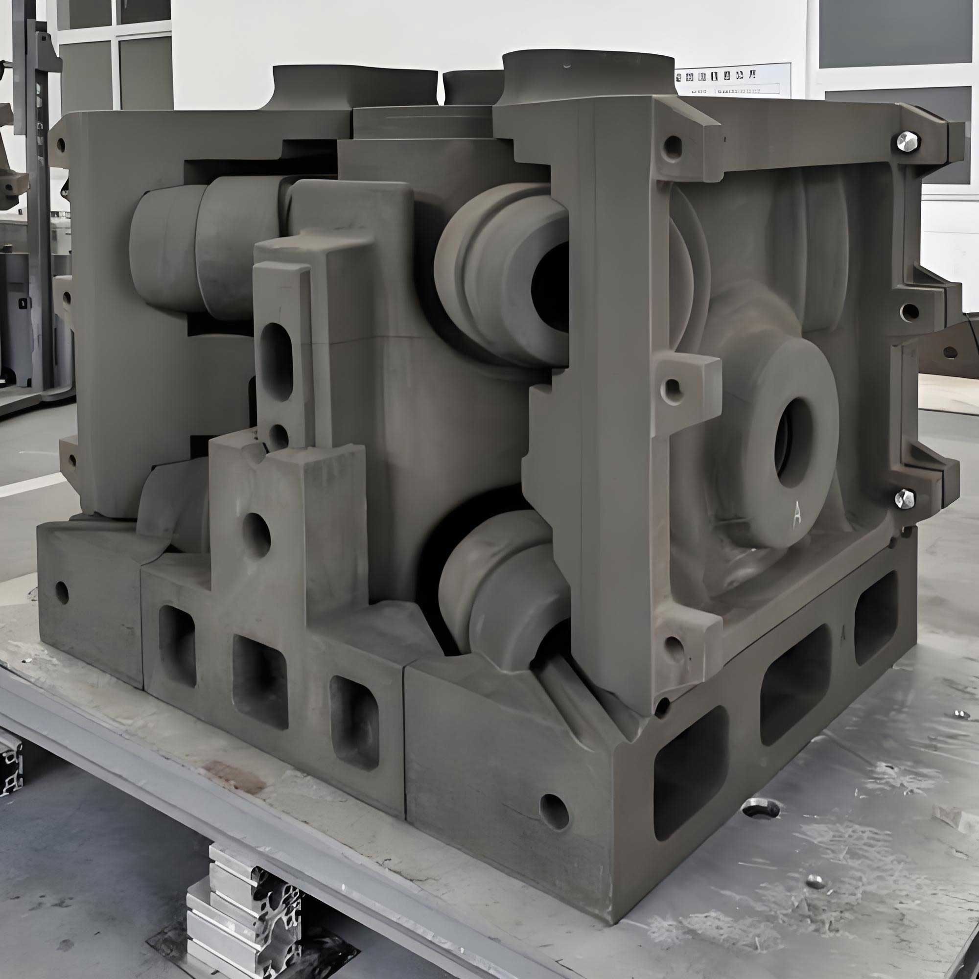
The entire value chain is interconnected. If the upstream binder is not stable, the machine cannot produce consistent cores. If the software does not compensate for shrinkage and binder penetration, the final casting will be out of tolerance. If the downstream user does not understand the design rules of 3d sand printing, the full potential of the machine will not be realized. Therefore, I strongly believe that promoting 3d sand printing requires a whole-chain perspective, not just the purchase of a machine.
Applications of 3D Sand Printing
3d sand printing has moved from laboratory research into mainstream foundry production. One of the most active application areas is the production of sand cores for internal cavities in castings. In conventional casting, a complex water jacket in a cylinder head or a valve body may require dozens of cores. With 3d sand printing, the core can be printed as one piece. This eliminates assembly variation and enables more optimized cooling geometries. I have seen automotive engine components that achieved better cooling performance because the printed core allowed curved conformal cooling channels that impossible to achieve with conventional core assemblies.
Aerospace is another important area. Aerospace castings are often highly complex, low volume, and made from expensive alloys such as nickel-based superalloys or titanium. The cost of a single casting can be very high. Any mistake in tooling is extremely expensive. With 3d sand printing, engineers can validate the casting design without committing to expensive tooling. They can print sand molds directly from the digital model, pour trial castings, inspect the results, and refine the design in a few weeks. This is a powerful way to compress development time and reduce risk.
The energy sector, especially large diesel engines, uses 3d sand printing for large cylinder blocks, cylinder heads, and exhaust manifolds. These components have intricate internal passages for air, oil, and water. The printed cores are dimensionally accurate and can be optimized to reduce pressure drops and improve thermal management. In one project I observed, the number of cores in a cylinder head was reduced from fifteen to three. This dramatically simplified assembly, reduced core shift, and improved the overall dimensional consistency.
The mold and tooling industry also benefits from 3d sand printing. Printed sand molds can be used to produce prototype castings before the final production tooling is available. This is particularly useful when a casting is designed for a new vehicle program and the delivery date is very tight. The ability to produce samples quickly allows downstream machining and assembly trials to begin earlier. In some cases, 3d sand printing is used for low-volume production, where the cost of conventional tooling is not justified. The following table summarizes typical applications.
| Industry | Typical Component | Benefit from 3D Sand Printing |
|---|---|---|
| Automotive | Cylinder head, block, water jacket | Integral core, reduced assembly, better cooling |
| Aerospace | Turbine housing, structural bracket | Rapid iteration, low quantity, expensive alloys |
| Energy and marine | Large diesel engine parts | Shorter lead time, optimized flow passages |
| Oil and gas | Valve body, manifold | Complex curved channels, small series |
| General machinery | Pump casing, gearbox housing | No pattern cost, design flexibility |
| Art and architecture | Sculptures, structural nodes | Geometric freedom, no draft constraints |
One of the most valuable applications is the digital spare part supply chain. Instead of storing heavy castings in warehouses for decades, companies can store the digital model and print the spare part on demand. This reduces inventory costs and eliminates the risk of obsolescence. I believe this will become a major future market for 3d sand printing, particularly for legacy equipment where original patterns have been lost or are too expensive to repair.
Efficiency Challenges in 3D Sand Printing
Despite all of the advantages, 3d sand printing is still slower than high-volume conventional molding lines. A modern automatic molding line can produce hundreds of sand molds per hour. A 3d sand printer, in contrast, may produce only a few hundred liters of printed sand per hour. This low productivity is one of the main obstacles to large-scale adoption. Foundry managers often ask me: how can we increase the output of 3d sand printing? The answer is not simple because productivity depends on many interrelated factors.
The total cycle time per layer can be modeled as the sum of several contributions. For a layer with a scanning length \(L_x\), a platform width \(L_y\), a printhead swath width \(w_{\text{swath}}\), and a scanning velocity \(v_{\text{scan}}\), the printing time is:
$$T_{\text{layer}} = \frac{L_y}{w_{\text{swath}}} \left( \frac{L_x}{v_{\text{scan}}} + t_{\text{index}} \right) + t_{\text{recoat}} + t_{\text{lower}} + t_{\text{additional}}$$
In this equation, \(t_{\text{index}}\) is the time required to step the printhead or platform between passes, \(t_{\text{recoat}}\) is the time to spread a new sand layer, \(t_{\text{lower}}\) is the time to lower the build platform by one layer thickness, and \(t_{\text{additional}}\) includes pause times, printhead maintenance, and any safety delays. The total build time is then:
$$T_{\text{total}} = N_{\text{layers}} \, T_{\text{layer}}$$
This formula shows that efficiency can be improved in four basic ways. First, reduce \(N_{\text{layers}}\) by using a larger layer thickness. Second, reduce \(L_x\) and \(L_y\) by optimizing part placement and batch layout. Third, increase \(v_{\text{scan}}\) and \(w_{\text{swath}}\) by using faster scan systems and wider printheads. Fourth, reduce the non-productive times \(t_{\text{recoat}}\), \(t_{\text{lower}}\), and \(t_{\text{index}}\). Each of these approaches has physical limits. For example, increasing layer thickness degrades surface quality and requires more binder to penetrate, which can cause bleeding. Increasing scan speed may cause incomplete binder penetration or printhead satellite droplets. Therefore, the optimal solution is usually a combination of improvements.
The volumetric productivity of the printer can be expressed as:
$$P_{\text{volume}} = \frac{A_{\text{build}} \, H_{\text{build}}}{T_{\text{total}}}$$
where \(A_{\text{build}}\) is the area of the build platform. In a dual-chamber printer, the two chambers can alternate between printing and recoating, which hides some of the non-productive time. I have seen this architecture in production machines. While one platform is being printed, the other platform is being lowered and recoated. This overlapping mode can increase effective productivity by twenty to thirty percent.
Another important efficiency factor is printhead utilization. A single printhead may have a swath width of only a few centimeters. The machine passes the printhead across the entire platform many times for each layer. If the number of nozzles is larger, the swath width is larger, and fewer passes are required. The number of passes per layer is:
$$N_{\text{pass}} = \frac{L_y}{w_{\text{swath}}}$$
If the platform has a width of 1000 mm and the printhead swath is 20 mm, the machine needs fifty passes. If the swath width can be increased to 40 mm, the number of passes is reduced to twenty-five. This is why printhead selection is so critical. Manufacturers continuously search for wider printheads with more nozzles and higher firing frequency. The deposition rate of a printhead is proportional to the droplet frequency, nozzle count, droplet volume, and the duty cycle:
$$\dot{V}_{\text{printhead}} = \eta_{\text{duty}} \, f_{\text{drop}} \, N_{\text{nozzle}} \, V_{\text{drop}}$$
where \(\eta_{\text{duty}}\) is the fraction of time the printhead is actually jetting binder. In practice, the duty cycle is less than one because the printhead must accelerate, decelerate, and turn around at the end of each pass. The acceleration and deceleration time can be modeled by the basic kinematic equation:
$$v^2 = v_0^2 + 2 a s$$
For a printhead with maximum acceleration \(a_{\max}\) and a move distance \(s\), the shortest point-to-point time is limited by the acceleration. A lighter printhead carriage or a more rigid gantry allows higher acceleration without exciting vibrations. In my work, I have seen significant efficiency gains from optimizing the printhead carriage structure. Reducing moving mass by thirty percent can increase permissible acceleration by almost the same amount, which reduces the turnaround time at the end of each scan.
Improving Printing Efficiency
There are several concrete strategies that I have used or observed for improving the efficiency of 3d sand printing systems. The most obvious is the selection of the printhead. A printhead with a higher native firing frequency allows faster scanning for the same lateral resolution. The width of the printhead must match the desired layer resolution and the required binder volume. Some systems use multiple printheads grouped into an array that covers a wider swath. The array can be staggered to reduce the gap between modules. When designing such an array, I have to consider thermal management, alignment, and maintenance access. If one printhead module fails, the entire array must be removable as a single unit to minimize downtime.
The second strategy is motion system optimization. The printhead should travel only the distance needed to cover the part, not the entire platform. Some machines implement a “follow-print” mode in which the platform moves under a stationary printhead instead of the printhead traveling over the platform. This reduces the moving mass and improves dynamic performance. Another approach is to use a multi-axis gantry with a lightweight carbon fiber beam. The drive system must be optimized for high speed and low vibration. A servo tuning process can reduce the settling time after each acceleration phase. In my experience, optimizing the motion profile can reduce the non-printing time by ten to fifteen percent without compromising accuracy.
The third strategy is to organize the printing process more compactly. For example, the platform can be lowered while the recoater is spreading the next layer, rather than waiting for the platform to stop. This is not possible in all machines, but modern control systems can overlap certain operations. The binder supply system can also be improved. If the binder is delivered at a constant pressure and the printhead is purged frequently, then the risk of nozzle clogging is reduced. Frequent purges consume binder and time. Therefore, an optimized printhead maintenance schedule is essential. I have seen a machine that reduces maintenance pauses by using a vacuum wiper system that cleans the nozzle face in only a few seconds.
The fourth strategy is to move toward multi-head printing. A large build volume can be divided into lanes, with each printhead responsible for a specific lane. The heads can scan simultaneously, reducing the total scanning time by half or more. However, simultaneous scanning creates a challenge in binder management and collision avoidance. The control software must coordinate the paths so that the heads do not interfere. The image of the industrial 3d sand printing setup that I inserted earlier represents the physical platform where such improvements are implemented.
The fifth strategy is to improve the recoating process. Sand spreading is often a bottleneck because the recoater must travel slowly enough to create a uniform layer. If the roller speed is too high, the sand layer becomes wavy or has thin spots. The relation between the final layer quality and the recoater speed is empirical. Some machines use a two-stage recoater: a fast bulk spreading pass followed by a slow leveling pass. Another approach is to use a compacted sand bed with a vibratory hopper, which improves sand density and reduces the need for multiple passes. A denser sand bed also improves the strength of the printed core because there are more contact points between sand grains. The packing density \(\rho_{\text{sand}}\) affects the final binder bridge area and therefore the strength of the mold.
The sixth strategy is to increase the layer thickness selectively. Many parts do not need high resolution in all areas. For example, the interior of a large core can be printed with a coarse layer thickness, while the exterior surface is printed with a thin layer. This is not possible with a conventional baseline process because the platform lowers by a fixed amount each cycle. But some newer machines support variable layer thickness if the sand spreading system can adapt. In my opinion, this is an important future direction. The volume of the part can be divided into a fine exterior shell and a coarser interior. The printer would then use a thinner layer for the first few layers and a thicker layer deeper inside the core. This reduces the total layer count while preserving the surface quality.
Let me summarize the main efficiency improvement strategies in the following table.
| Strategy | Implementation | Expected Impact |
|---|---|---|
| Wider printhead array | Use more nozzles or multiple modules | Fewer passes per layer |
| Higher firing frequency | Select fast printhead and precise drive | Higher scan speed |
| Lightweight gantry | Carbon fiber, optimized structure | Higher acceleration, less turnaround time |
| Dual chamber operation | Alternate printing and lowering/recoating | Hide non-productive time |
| Rapid recoating | Two-stage spreader, optimized roller | Reduced t_recoat |
| Maintenance schedule | Predictive nozzle cleaning, vacuum wiper | Fewer pauses, higher uptime |
| Variable layer thickness | Adaptive slicing for coarse and fine regions | Lower layer count, shorter build time |
In addition to machine-level efficiency, the overall factory efficiency also depends on material handling. In a mature 3d sand printing production line, printed cores must be moved from the printer to a curing station, then to a depowdering station, and then to an inspection point. If these steps are performed manually, the labor cost and cycle time increase. Many smart foundries now use conveyors, robotic grippers, and automatic guided vehicles to integrate the printer with the rest of the casting process. The objective is to reduce the idle time between the printer finishing a job and the next job starting. This is called the “job change time.” In traditional printing, changing the job requires sweeping the powder bed, cleaning the printhead, and loading new machine data. Some of this can be automated. I have seen machines that can prepare the next print job in less than fifteen minutes because the sweeping and cleaning systems are integrated into the machine frame.
Formulas and Key Performance Indicators
To evaluate any 3d sand printing process, I usually define a set of key performance indicators. The first is net productive time, which is the time that the printhead is actively jetting binder. This is related to the ratio of the binder deposition rate to the maximum possible deposition rate. The second is the sand utilization efficiency, which is the ratio of the sand volume in the final core or mold to the total sand volume in the build box:
$$\eta_{\text{sand}} = \frac{V_{\text{core}}}{V_{\text{box}}}$$
This is important because the loose sand that is not bound must be reclaimed. A higher packing density means more sand in the box, but the utilization factor is usually below five percent for very small cores. For large molds, the utilization can be above thirty percent. The energy consumption per printed core can be estimated as:
$$E_{\text{core}} = E_{\text{transport}} + E_{\text{spreading}} + E_{\text{jetting}} + E_{\text{curing}} + E_{\text{reclaim}}$$
Each of these energy terms depends on the machine design and the process parameters. Inorganic binders often require a drying step, which consumes significant energy. The trade-off between binder system and energy consumption is an important consideration. Furan systems cure at room temperature but emit volatile organic compounds. Inorganic systems are cleaner but often require heated air drying. The selection of the binder system is therefore both a technical decision and an environmental decision.
The surface quality of the printed sand core can be characterized by the average roughness \(R_a\). The layer thickness and the sand grain size are the two main parameters that influence this roughness. A simple empirical model for the theoretical step roughness is:
$$R_a \approx \frac{h_{\text{layer}}}{2 \tan \alpha}$$
where \(\alpha\) is the local inclination angle of the surface. For a vertical wall, \(\alpha = 90^\circ\), and the roughness is very low because the layer edge is nearly vertical. For a shallow inclined surface, the stair-step effect is more visible. Therefore, designers should orient the core so that critical surfaces are as vertical as possible. In 3d sand printing, part orientation is a free design variable because there is no need to satisfy the draft angle. This is a significant advantage over conventional casting, where the orientation is constrained by the pattern drawing direction.
Another important performance indicator is the binder penetration depth, which can be controlled by the drop spacing and the amount of binder applied. If the binder penetration is too deep, the edge of the printed core becomes rounded, affecting the dimensional accuracy. If it is too shallow, the inter-layer bond may be weak. The optimum binder amount is often expressed as the saturation ratio, which is the ratio of the actual binder volume to the void volume in the sand:
$$S = \frac{V_{\text{binder}}}{V_{\text{void}}}$$
For a typical furan binder system, the saturation ratio is between 0.2 and 0.6. In my experience, a saturation ratio above 0.7 causes excessive bleeding, while a ratio below 0.15 results in friable cores. The machine software can adjust the saturation by changing the drop spacing in the x and y directions. The drop spacing \(d_{\text{drop}}\) is related to the printhead velocity and droplet frequency:
$$d_{\text{drop}} = \frac{v_{\text{scan}}}{f_{\text{drop}}}$$
If the scan speed is doubled, the drop spacing is doubled unless the firing frequency is increased correspondingly. This is why high-frequency printheads enable both high speed and high resolution.
Future Trends in 3D Sand Printing
Looking forward, I see several clear trends in 3d sand printing. The first is the diversification of equipment. The early industrial printers were all designed to be as large as possible. Today, there are compact machines for job-shop foundries, medium-size machines for general casting, and very large machines for marine and energy components. There are also dual-box machines that allow the operator to unload one build box while the other is printing. This increases machine utilization significantly. In the future, I expect to see more modular machines in which the build box width can be extended by adding segments. This will allow a foundry to scale its 3d sand printing capacity incrementally rather than buying a new machine.
The second trend is the localization of materials and components. Many countries are building domestic supply chains for printheads, binders, and specialized sand. This reduces the delivery time and technical dependency. I have also seen the emergence of local software platforms that support machine monitoring, job scheduling, and quality traceability. The software is becoming a differentiator in the 3d sand printing market. In the future, the machine itself may be a commodity, and the value will shift to software and process knowledge. The machine will be a connected node in a digital foundry network, reporting its productivity, quality, and maintenance needs in real time.
The third trend is the integration of 3d sand printing into smart factories. I have observed production lines where several 3d sand printers are connected by an automated guided vehicle system. Printed cores move through an automatic depowdering station, where robotic brushes clean the cores. Then they are coated automatically and transported to a robotic mold assembly cell. The entire process is monitored by a manufacturing execution system. This level of automation reduces the need for workers in dusty environments and improves the consistency of quality. The concept of a “lights-out foundry” is no longer science fiction. It is being implemented step by step.
The fourth trend is the improvement in binder systems. Environmental regulations are pushing foundries away from solvent-based resin systems. Inorganic binders are receiving more attention because they produce no harmful emission during pouring, and the sand can be reclaimed more easily. The main disadvantage is the need for careful drying and lower humidity resistance. I believe that new hybrid organic-inorganic binders will solve these problems. The development of a dual-cure binder system, where the first cure occurs during printing and the second cure occurs during the core assembly process, could reduce the time between printing and pouring significantly. This would increase the productivity of the whole foundry, not just the printer.
The fifth trend is the use of simulation and artificial intelligence to optimize the printing process. A machine learning model can predict the final strength and dimensional accuracy of a printed core based on the process parameters, the sand type, and the binder recipe. Instead of doing trial-and-error experiments, the engineer can use the model to find the best parameters. This is particularly useful for new materials. I have worked with a process optimization model that used a simple multiple regression equation:
$$\sigma_{\text{core}} = \beta_0 + \beta_1 S + \beta_2 \rho_{\text{sand}} + \beta_3 h_{\text{layer}} + \beta_4 T_{\text{cure}}$$
where \(\sigma_{\text{core}}\) is the core strength, \(S\) is the binder saturation, \(\rho_{\text{sand}}\) is the bed density, \(h_{\text{layer}}\) is the layer thickness, and \(T_{\text{cure}}\) is the curing temperature. The coefficients \(\beta_i\) must be calibrated from experiments, but once they are known, the model can guide parameter selection. In the future, such models will be built into the machine software, allowing the operator to simply enter the desired core strength and the software will calculate the optimal printing parameters.
The sixth trend is standardization. The 3d sand printing industry is still young and lacks comprehensive standards. Different machine manufacturers use different test methods for core strength, surface roughness, and dimensional accuracy. This makes it difficult for foundries to compare systems and for customers to specify requirements. I believe that national and international standards will be developed for raw material quality, process parameters, calibration methods, and safety requirements. Standards will not stifle innovation; they will build trust and accelerate market growth. The following table lists the areas where I expect standardization to be most valuable.
| Standard Area | Purpose | Typical Measurement |
|---|---|---|
| Sand materials | Consistent grain size, shape, thermal properties | AFS grain fineness, angularity, acid demand |
| Binder behavior | Stable curing and strength development | Viscosity, solids content, reactivity |
| Printed core strength | Uniform mechanical performance | Bending strength, tensile strength |
| Dimensional accuracy | Comparable tolerances between machines | Coordinate measurement of test piece |
| Surface finish | Predictable casting surface quality | Surface roughness Ra |
| Machine safety | Protect operators and environment | Emission levels, electrical safety |
Economic Impact and Business Models
The economic impact of 3d sand printing extends beyond the foundry floor. It changes the supply chain for spare parts. Instead of maintaining a large warehouse of castings for equipment that may never need replacement, a company can store the digital files and print the parts only when an order is received. The cost of digital inventory is much lower than the cost of physical inventory. The delivery time is longer than a warehouse delivery but often much shorter than a pattern-based casting process. In many maintenance applications, this trade-off is acceptable because the plant can schedule maintenance in advance.
The total cost of ownership for a 3d sand printing system includes purchase price, installation, tooling, materials, labor, energy, maintenance, and downtime. In my experience, the purchase price is only one part of the total lifetime cost. The largest operating cost is usually the binder, followed by labor and energy. The sand is not a major cost if the sand is reclaimed. The cost per printed core can be expressed by the following equation:
$$C_{\text{core}} = \frac{C_{\text{machine}} / L_{\text{life}} + C_{\text{maintenance}} + C_{\text{material}} + C_{\text{energy}} + C_{\text{labor}}}{N_{\text{core}}}$$
where \(L_{\text{life}}\) is the machine service life in years or hours, and \(N_{\text{core}}\) is the number of cores produced in the same period. The denominator \(N_{\text{core}}\) makes it clear that the utilization rate is crucial. A machine that runs 24 hours a day has a much lower cost per core than a machine that runs only eight hours a day. Therefore, many foundries are moving toward multi-shift operation and remote monitoring. Some companies place the machine at a central service hub and sell printed cores to multiple clients, which increases utilization and reduces the cost for all users.
The business model of 3d sand printing is also evolving. In the past, a machine manufacturer sold machines and provided maintenance. Today, some manufacturers offer “print as a service” contracts with a guaranteed number of printed liters per month. This reduces the capital risk for foundries. It also forces the machine manufacturer to improve reliability and productivity, because the revenue depends on the output of the machine. I expect this business model to grow, especially for small and medium foundries that want the advantages of 3d sand printing without a large capital investment.
Another important economic dimension is the cost of design changes. In a traditional foundry, a minor design change may require a new pattern and a long delay. In 3d sand printing, the cost of a design change is simply the cost of updating the CAD model and running another print job. The lead time for a design iteration can be reduced from six weeks to one week. This accelerates the whole product development process. In industries where speed to market is critical, this advantage can be far more valuable than the direct printing cost. I often use the concept of “time value of design iterations” to explain this. If a faster design cycle allows a company to enter the market one month earlier, the additional revenue may be much larger than the cost of the printed prototype.
Integration with Robotic and Digital Technologies
3d sand printing does not operate in isolation. It is most powerful when integrated with other digital manufacturing technologies. For example, a robotic arm can apply a refractory coating to a printed core immediately after depowdering. The coating is essential for achieving a good casting surface finish. The robot can follow the complex surface of the core precisely, which is difficult to do by hand. I have seen a cell where the 3d sand printer, the depowdering station, and the coating robot are connected by a conveyor. The entire process is coordinated by a programmable logic controller. The cell can run for many hours without human intervention.
The digital thread also includes inspection. Printed sand cores can be scanned by a 3D structured-light scanner and compared to the original CAD model. The dimensional deviation can be visualized as a color map. This is extremely useful for qualifying the process. The inspection data can be stored with the digital model to create a complete quality record. In the future, artificial intelligence will analyze this data and automatically adjust the printing parameters to compensate for drift. For example, if the core thickness is consistently 0.2 mm too large, the software can modify the CAD model by subtracting 0.2 mm from the affected surfaces. This closed-loop compensation will make 3d sand printing even more precise.
Material Considerations and Quality
The quality of a 3d printed sand mold depends on the interaction between sand and binder. The grain shape is important. Rounded grains pack more densely and use less binder, but they may have lower mechanical interlocking. Angular grains provide better strength at the same binder level but create higher porosity and more surface roughness. The grain size distribution affects the permeability of the mold. A higher permeability allows the gas generated during casting to escape more easily, reducing the risk of gas defects. The relationship between permeability and average grain size is often modeled as:
$$K \propto d_{\text{grain}}^2$$
where \(K\) is the permeability and \(d_{\text{grain}}\) is the mean sand grain diameter. However, the presence of fines can reduce permeability significantly. In 3d sand printing, the sand is not compacted by ramming or blowing, so the bed density is lower than in conventional no-bake molds. This can affect thermal conductivity and permeability. I have found that using a coarser sand for large molds and a finer sand for surface-critical cores is a good practice. Some foundries use mixed sand to balance strength and surface finish.
The binder system also plays a major role in casting quality. Furan binders are popular because of their fast cure and excellent strength. However, they contain nitrogen and sulfur, which can cause defects in steel castings. Phenolic urethane binders cure quickly with amine gas and are suitable for many metals. Inorganic binders are the most environmentally friendly but have lower humidity resistance. The following table compares the binder families that I commonly see in 3d sand printing.
| Binder Type | Curing Mechanism | Advantages | Limitations |
|---|---|---|---|
| Furan resin | Acid-catalyzed condensation | High strength, low cost | Nitrogen and sulfur potential |
| Phenolic urethane | Amine gas curing | Fast cure, low temperature | Amine odor, VOC emissions |
| Phenolic acid | Heat or acid curing | Good for steel | Requires careful humidity control |
| Inorganic silicate | Evaporative drying | No VOC, clean casting | Humidity resistance lower |
| Hybrid organic/inorganic | Dual-cure | Balanced properties | Still in development |
Quality control in 3d sand printing is not only about the finished core. In my process audits, I check the sand bed density, the binder saturation, the printhead health, and the environmental conditions. A deviation in any of these parameters can cause defects that appear only after casting. For example, if the air humidity is too high, the sand bed absorbs water, which can delay the binder cure and reduce core strength. If the printhead nozzles are partially clogged, the saturation will be uneven and the core may have weak spots. Machine software should monitor the droplet ejection and correct for clogged nozzles automatically. I have seen systems that use a camera to inspect each jet and activate a purge cycle when a nozzle is weak. This kind of built-in quality assurance is essential for industrial production.
Research Directions and Open Problems
Although 3d sand printing is already a commercial technology, I see many open problems that deserve research. The first is multi-material printing. Current machines print with one type of sand and one binder. In the future, it may be possible to print a mold with a high-strength surface layer and a permeable core region. This would require the ability to switch between different sands or binders during the build process. Multi-material 3d sand printing would allow graded properties in the mold, such as high thermal conductivity near the casting surface and low thermal conductivity elsewhere. This is a complex but exciting direction.
The second research area is the real-time monitoring of the powder bed. If the machine can measure the density and moisture of the sand before printing, it can adjust the binder saturation on the fly. Optical coherence tomography, thermal imaging, and acoustic sensors are possible methods. I believe that the first machine with an automatic layer-quality control system will appear soon. This will reduce scrap and make the process more robust.
The third research area is the simulation of the printing process itself. A model that can predict binder flow through the porous sand bed, the curing reaction, and the stress development in the core would be very valuable. The scale of the model is challenging because the pore size is on the order of 100 micrometers, while the core is on the order of 1 meter. Multi-scale simulation methods are needed to bridge this gap. Such a model could optimize the printing parameters without wasting material on trial prints. The governing equation for the binder flow in the porous sand bed is based on Darcy’s law:
$$q = -\frac{K}{\mu} \nabla p$$
where \(q\) is the Darcy flux, \(K\) is the permeability, \(\mu\) is the binder viscosity, and \(\nabla p\) is the pressure gradient. The saturation front moves according to the capillary pressure and the binder viscosity. If this model is accurate, the machine software could predict the optimum drop spacing for each layer. In my view, this is the next frontier for 3d sand printing research.
The fourth research area is the mechanical strength of printed sand. The binder bridges between sand grains are tiny and brittle. The macroscopic strength depends on the number of contacts per unit volume, the strength of each bond, and the distribution of stress. The Weibull distribution is often used to describe the variability of brittle strength:
$$P_f(\sigma) = 1 – \exp\left[-\left(\frac{\sigma}{\sigma_0}\right)^m\right]$$
where \(P_f\) is the probability of failure, \(\sigma_0\) is the characteristic strength, and \(m\) is the Weibull modulus. A higher Weibull modulus means less variability and more reliable cores. By optimizing the printing process, I have seen the Weibull modulus increase from about 8 to more than 15. This is a significant improvement in process reliability.
Workforce and Organizational Change
The adoption of 3d sand printing changes the skills needed in a foundry. There may be less demand for pattern makers and core makers, but there is more demand for CAD designers, process engineers, and automation technicians. The foundry worker does not disappear; the nature of work changes. In my experience, the most successful companies invest in retraining their existing workforce. A traditional core maker understands the fundamentals of sand, binder, and casting defects. That knowledge is very valuable for designing print parameters. The individual should be trained to work with digital models and machine interfaces. The result is a workforce that combines the experience of the old foundry with the tools of the digital age.
Organizational change is also necessary. If a foundry treats 3d sand printing as just another machine, it will not get the full benefit. The design department needs to develop new design rules for additive molds. The quality department needs to accept digital inspection methods. The management needs to change its cost accounting to reflect the value of speed and flexibility. I have seen foundries fail because they tried to implement 3d sand printing with the same workflows and mental models as traditional casting. The technology is disruptive, and it requires a radical rethinking of the entire production process.
The role of simulation and digital twin will become more central. A digital twin of the foundry can simulate the entire process from printing to pouring to cooling. The twin can be used to test production schedules, optimize the use of machines, and train operators. In the future, the 3d sand printing machine will be part of an integrated digital twin that also includes the melting furnace, the pouring line, and the heat treatment process. This will allow the factory to be operated proactively rather than reactively. When an order comes in, the system will automatically design the mold, simulate the casting, schedule the print job, and issue the manufacturing order. This is the true smart factory vision.
The Role of Government and Industry Policy
Government support has played an important role in the development of 3d sand printing. In my country, national action plans have set targets for the growth of additive manufacturing. These plans encourage the development of new materials, equipment, and applications. They also promote industry-academia collaboration. The result is a more vibrant ecosystem of startups, established manufacturers, and research institutes. However, I have also seen policies that focus too much on purchasing hardware and not enough on software, training, and standardization. A balanced policy should support the entire industrial chain, including basic research, engineering services, and the development of industry standards. In this way, 3d sand printing will become a sustainable manufacturing technology, not a temporary novelty.
The international comparison is interesting. Some countries are ahead in printhead technology and advanced materials, while others are ahead in application engineering and cost reduction. In the future, I expect more global cooperation and also more regional competition. The countries that embrace digital manufacturing and train their workforce will be the leaders in 3d sand printing. The countries that protect old production methods will fall behind. The transition may be uncomfortable, but it is inevitable.
How to Evaluate a 3D Sand Printing Solution
For a foundry manager who is considering 3d sand printing, I would recommend a structured evaluation. First, define the target applications. Are they complex internal cores, large molds, or small prototype castings? The required build box and precision will follow from the target applications. Second, measure the current costs and lead times for those applications. This provides a baseline. Third, calculate the total cost of ownership of the printer, including material cost, maintenance, labor, and downtime. Fourth, do a benchmark test with the actual foundry sand and binder system. The test piece should include thin walls, sharp corners, and internal channels. Fifth, evaluate the software workflow. Does the software automatically generate the shell of the mold? Does it calculate shrink compensation? Does it support nesting multiple cores in one build box? Sixth, consider the service network of the equipment manufacturer. A 3d sand printing machine is not a simple machine; it requires process support. A good manufacturer helps with binder selection, print parameter optimization, and troubleshooting.
I have developed a simple scoring table for evaluating 3d sand printing suppliers. The table considers performance, cost, service, and risk. It can be adapted to the specific needs of a foundry. An example is shown below.
| Evaluation Criterion | Weight | Supplier A Score | Supplier B Score |
|---|---|---|---|
| Print speed | 20% | 8 | 7 |
| Dimensional accuracy | 20% | 9 | 8 |
| Material cost | 15% | 6 | 8 |
| Software usability | 15% | 8 | 7 |
| Service and support | 15% | 9 | 6 |
| Installation and downtime | 10% | 7 | 9 |
| Total weighted score | 100% | 7.85 | 7.35 |
This type of structured comparison helps the decision maker avoid being influenced by only the purchase price. In my experience, the cheapest machine is often not the most economical over a five-year period because of material consumption and downtime. The machine that is slightly more expensive but more reliable and better supported will produce more cores and have a lower total cost.
Training and Knowledge Transfer
Training is the most underestimated factor in the successful implementation of 3d sand printing. Operators must learn how to prepare the job file, calibrate the printhead, monitor the binder supply, and troubleshoot common defects. Maintenance personnel must learn how to replace the recoater, clean the printhead, and calibrate the platform. Designers must learn how to design for binder jetting. They need to know the minimum wall thickness, the minimum core feature size, and the tolerances. I have seen many issues arise not from machine failure, but from operator error. Therefore, I always recommend a comprehensive training plan as part of the machine purchase. The training should include not only the machine operation but also the casting process, because the quality of the final casting is the ultimate target.
Knowledge transfer is not a one-time event. As the technology evolves, the foundry must keep learning. It is important to participate in user groups, industry conferences, and technical workshops. The 3d sand printing community is still small, and many practitioners are willing to share their experience. I myself have learned from other foundries just as much as from my own experiments. The best companies create a culture of continuous improvement, where every failed print is an opportunity to learn. The data from each print job should be stored and analyzed. Over time, this creates a knowledge base that is a competitive advantage.
Practical Advice for Implementing 3D Sand Printing
If I were to give practical advice to a foundry starting with 3d sand printing, I would say: start small, but think big. A compact machine can be used to validate the process and build internal knowledge. Once the foundry has a stable workflow, it can scale up. It is also wise to start with a few castings that are very difficult to produce with conventional tooling. This creates a visible success and helps convince the rest of the organization. Do not start with simple parts that could be made more cheaply by conventional casting. The goal is not to replace the cheapest process, but to enable things that were impossible before.
Another piece of advice is to involve the casting designer early. The designer should know whether the final core will be printed as a single piece or assembled from multiple printed pieces. This affects the design of internal cores and the placement of shrink allow. The designer must also understand the minimum feature size. In 3d sand printing, very sharp corners can be printed, but very thin ceramic-like features may be fragile. The minimum wall thickness for a sand core is usually around 3 to 5 mm, depending on the sand grain size and the binder system. The table below shows approximate design rules that I use in practice.
| Design Parameter | Typical Value | Remarks |
|---|---|---|
| Minimum feature size | 0.5 to 1 mm | Depends on sand grain size |
| Minimum wall thickness | 3 to 5 mm | Needed for handling strength |
| Layer thickness | 0.2 to 0.5 mm | Resolution and speed trade-off |
| Minimum draft | 0 degrees | No pattern removal needed |
| Core print clearance | 0.2 to 0.5 mm | Avoid crushing during mold close |
| Maximum overhang | Unlimited with support | Powder bed supports the geometry |
The design rules are different from conventional casting, and this is exactly why the investment in training is necessary. A designer who knows the possibilities of 3d sand printing can create a casting with fewer cores, better channelling, and improved structural performance. The design becomes a selling point for the foundry.
Conclusion
In this article, I have shared my perspective on 3d sand printing from the foundry floor to the digital factory. I have discussed the fundamental principles of additive manufacturing and explained why 3d sand printing is such a disruptive technology for casting. The ability to produce complex sand molds and cores directly from a digital model eliminates the traditional pattern-making bottleneck, shortens lead time, improves accuracy, and enables design freedom that is impossible with conventional tooling. The environmental benefits of a cleaner, quieter, and more ergonomic foundry are also significant.
I have also examined the industrial chain, showing that 3d sand printing depends on the coordinated development of materials, components, software, equipment, and services. The upstream supply of sand and binder is critical; the midstream equipment and platform offering defines productivity; and the downstream applications create value. The entire industry is still maturing, and standardization will play a key role in its healthy growth.
Efficiency remains one of the biggest challenges. In my view, the future productivity of 3d sand printing will be driven by wider multi-head arrays, lighter motion systems, faster recoating, smarter job scheduling, and adaptive process control. The equations and tables presented here give a quantitative view of the factors that determine print speed and cost. By optimizing these factors, I believe the throughput of 3d sand printing can be raised to the level where it becomes competitive with conventional mold lines for medium-volume production as well as prototype work.
The future of 3d sand printing is not only about faster machines. It is about the convergence of additive manufacturing, robotics, simulation, and artificial intelligence. The foundry of the future will be a digital, green, and highly flexible factory. I expect to see more integrated production cells, more automated material handling, and more intelligent process control. In such a factory, the worker will be a supervisor of machines, not a performer of heavy labor. The core value of 3d sand printing will be its ability to respond quickly to a changing world. The digital model is the new tooling, and the printer is the new mold shop. That is why I am convinced that 3d sand printing will be not only an important manufacturing technology but also a driver of industrial transformation.