
In my years of working with casting technologies, I have witnessed a fundamental shift in how foundries approach pattern making, mold production, and the overall casting workflow. The traditional sand casting process, while reliable, is burdened by multiple complex stages including pattern design, core box fabrication, tooling setup, and manual mold assembly. As competition intensifies and product cycles shorten, the demand for low-volume production and rapid prototyping has exposed the limitations of conventional methods. This is exactly where 3d sand printing has transformed the landscape. In this article, I will share my practical experience with 3d sand printing, from common solid sand molds to hollow lattice structures, and explain why this additive manufacturing approach is now a cornerstone of modern foundries.
My primary focus is on the micro-droplet jetting principle, which is the foundation of most commercial 3d sand printing systems. By selectively depositing a binder onto thin layers of sand, the printer builds up a three-dimensional mold or core with remarkable geometric freedom. Unlike subtractive methods, 3d sand printing does not require any dedicated tooling, and the digital workflow allows direct transition from CAD model to finished sand package. In practice, I have used this technology to create engine turbocharger housings, aerospace cabin components, and various mechanical parts that would be extremely difficult or even impossible to produce using traditional pattern-based methods. The benefits are not just limited to geometry; they extend to controlling cooling rates, reducing material usage, and shortening manufacturing lead times.
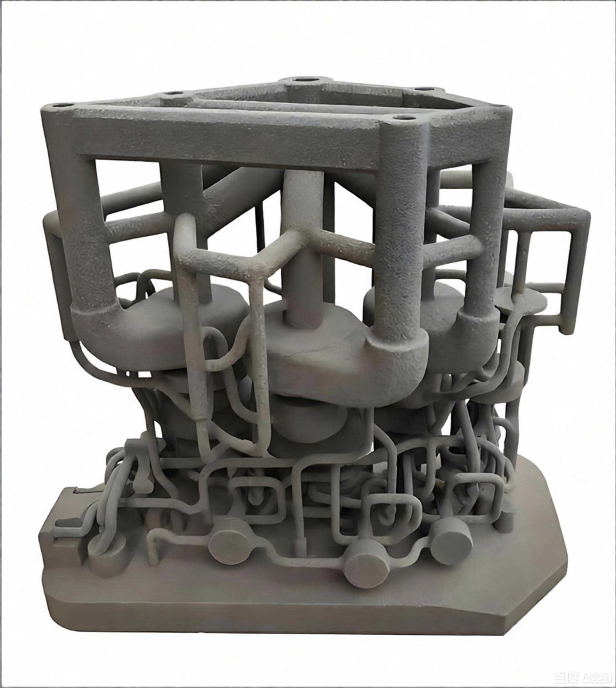
Throughout this article, I will describe the step-by-step methodology I follow for two representative applications: a crankshaft mold made with ordinary solid sand 3d sand printing, and an intermediate bearing housing made with hollow lattice sand 3d sand printing. I will also discuss the design parameters, the slicing and file generation workflow, the actual printing process, and the essential maintenance procedures that ensure consistent output quality. Tables and mathematical formulas will be used to clarify the dimensional parameters, material properties, and process calculations. The image below shows a typical industrial sand mold fabricated by 3d sand printing, illustrating the level of detail achievable in practice.
1. Fundamentals of 3D Sand Printing
3d sand printing belongs to the family of binder jetting additive manufacturing processes. The working principle can be described as follows: a recoater spreads a thin layer of sand across the build platform; then a print head, similar to an inkjet printer, moves over the sand bed and jets micro-droplets of a liquid binder onto the areas that correspond to the solid cross-section of the mold. The binder coats the sand grains and cures them, bonding adjacent grains together. The platform then lowers by one layer thickness, and the process is repeated until all layers have been printed. After printing, the loose unbonded sand is removed, leaving behind the finished sand mold or core.
One of the key parameters in 3d sand printing is the droplet volume, which is typically on the order of picoliters. The tiny droplet size enables a high resolution and a smooth surface finish on the printed sand parts. The layer thickness, binder saturation, print head resolution, and sand particle size all influence the final mold quality. In my work with the CAMTC-SMP600/1500/2000 series of sand printers, I have found that the integration of a dual sand spreading and printing unit, combined with a layered heating and compaction system, significantly improves printing efficiency and mechanical strength of the molds. The control software is equally important; it converts STL data into a series of bitmap images that define the binder jetting pattern for each layer.
Let me formalize the governing equation for the volume of binder deposited per layer. If we denote the print head resolution as \(R_x\) and \(R_y\) in dots per inch, the layer thickness as \(t\), and the target binder saturation as \(S\) (expressed as a fraction of the void volume in the sand bed), then the total volume of binder per unit area can be calculated. The porosity \(\phi\) of the packed sand bed is typically in the range of 0.35 to 0.45. The binder volume \(V_b\) required for a layer of area \(A\) is given by:
$$ V_b = A \cdot t \cdot \phi \cdot S $$
where \(t\) is the layer thickness, \(\phi\) is the porosity, and \(S\) is the desired saturation. In practical terms, for a layer of 1 square meter with a thickness of 0.3 mm, a porosity of 0.4, and a saturation factor of 0.15, the binder volume would be:
$$ V_b = 1 \times 0.0003 \times 0.4 \times 0.15 = 1.8 \times 10^{-5} \ \text{m}^3 = 18 \ \text{ml} $$
This calculation helps me set up binder consumption estimates and predict production costs. Another important parameter is the printing speed, which is influenced by the number of print passes, the swath width of the print head, and the moving velocity. Let \(v\) be the scanning speed, \(W\) the effective print swath width, and \(L\) the length of the layer. The time \(T_{layer}\) to print one layer can be approximated as:
$$ T_{layer} = \frac{L}{v} \times \frac{1}{W} \times \left(1 + \frac{t_{recoating}}{t_{printing}}\right) $$
where the last term accounts for the recoating time relative to the jetting time. In the machines I have used, the recoating process is optimized by the dual spreading device, which spreads sand in both directions without needing to return empty. This reduces the non-productive time by up to 40% compared to traditional single-direction spreading.
2. Crankshaft Mold by Conventional Sand 3D Printing
My first practical demonstration of 3d sand printing was the production of a crankshaft casting mold. The crankshaft has a complex outline with counterweights, connecting rod journals, and oil passages. In traditional casting, this would require multiple core boxes and a carefully designed gating system. With 3d sand printing, I can design the entire mold digitally and print it in one piece or in a few sections that are then assembled.
2.1 Gating System Design for the Crankshaft Mold
The design process begins with the pouring system. I need to determine the number of ingates, their positions, and the dimensions of the sprue and runner system to ensure clean filling and minimize turbulence. A well-designed gating system prevents defects such as gas entrapment, slag inclusion, and shrinkage porosity. For the crankshaft, I used a pressurized gating system with one sprue, a horizontal runner, and multiple ingates. Table 1 summarizes the key dimensions of the gating system used in this case.
| Component | Parameter | Value (mm) |
|---|---|---|
| Pouring cup | Top diameter | 80 |
| Pouring cup | Bottom diameter | 45 |
| Sprue | Length | 200 |
| Sprue | Top diameter | 45 |
| Sprue | Bottom diameter | 30 |
| Runner | Cross-section (width × height) | 40 × 35 |
| Ingate | Number | 4 |
| Ingate | Cross-section per ingate | 20 × 15 |
| Exhaust riser | Diameter | 25 |
The gating ratio for this system is:
$$ A_{sprue} : A_{runner} : A_{ingates} = 1 : 1.2 : 1.5 $$
With \(A_{sprue} = \pi (0.5 \times (45+30)/2)^2\) approximately. Actually, the sprue is tapered, so the effective area is taken at the choke point, which is the bottom of the sprue:
$$ A_{sprue} = \pi \left(\frac{30}{2}\right)^2 = 706.9 \ \text{mm}^2 $$
The total ingate area is:
$$ A_{ingates} = 4 \times (20 \times 15) = 1200 \ \text{mm}^2 $$
Thus the actual ratio relative to the choke area is \(706.9 : 848.3 : 1200\), which gives approximately \(1 : 1.2 : 1.7\). This ensures proper filling without excessive velocity.
2.2 Parting Line and Orientation
After designing the gating system, I need to establish the parting line. For the crankshaft mold, the parting line was set at the horizontal plane passing through the centerline of the crankshaft and the sprue. This choice simplifies the mold construction and allows the crank webs to be distributed equally in the cope and drag. In the slicing software, I divided the mold into two halves: the upper half and the lower half. The parting design involves five main steps, which I will outline in Table 2.
| Step | Description | Software/Action |
|---|---|---|
| 1 | Define the parting surface | Use the curve through the central axis of the crankshaft |
| 2 | Set injection mold wizard parameters | Define contraction compensation and draft angles |
| 3 | Create the containment volume | Bounding box around the outside of the mold |
| 4 | Position the component | Align the crankshaft axis with the z-direction |
| 5 | Export the separate mold halves | Export as two STL files |
It is critical to orient the part properly. For parts with surface textures or critical features, I always place those features upward so that the printed surfaces have good quality without support interference. In the crankshaft case, the oil holes were oriented vertically to avoid the need for any internal supports. The parting line is designed to ensure that the mold halves can be separated easily after casting.
2.3 From STL to Sliced Images
The typical data workflow for 3d sand printing involves several software tools. First, I export the CAD model as an STL file. Then I use a data preparation software such as Magics to fix errors, orient the part, and merge all components. Magics is widely used for rapid prototyping and additive manufacturing; it allows me to handle mesh repairs, wall thickness analysis, and scaling. For the crankshaft mold, I performed the following steps:
1. Output the crankshaft sand mold STL. If the part contains decorative features, thin walls, or threads, the orientation is crucial. For example, if a decorative feature is placed face down, the support structures may come into contact with that surface, leaving marks that require post-processing. The correct orientation is to place the decorative face upward, ensuring a smooth surface finish. For threaded features, the orientation must preserve the thread profile to allow subsequent assembly.
2. Adjust the position of the valve block mold (in the case of a more complex assembly). I make sure that every component is within the build envelope and that the minimum z-height corresponds to the lowest point of the model.
3. Merge all parts and output a combined STL file. This ensures that all parts are printed in a single build and remain accurately positioned relative to each other.
4. Use the slicing tool to generate layered images. The software I use is a dedicated slicing program called 3DPSlice, developed for the digitized sand printing precision forming machine. This tool converts the STL file into a series of BMP or PNG images. The process includes:
- Setting the parameters (layer thickness, image resolution, etc.)
- Loading the model file
- Slicing the model into horizontal cross-sections
- Generating the layer images
One important parameter is the effective image width of the print head. The physical print head is assembled with overlapping nozzles, so the effective image width (in pixels) must be calibrated. A practical method is to print a test pattern and adjust the width value until no visible overlapping or gap appears. Table 3 lists the typical slicing parameters I use for a sand mold with a resolution of 1000 pixels across the print head.
| Parameter | Value | Remark |
|---|---|---|
| Layer thickness | 0.3 mm | Adjustable from 0.2 to 0.5 mm |
| Image width | 1000 pixels | Based on print head calibration |
| Image height | Variable | Depends on model length |
| Resolution | 100 dpi | Enough for sand molds |
| Binder saturation | 15% | Can be adjusted for strength |
| Z-compensation | 0.05 mm | Compensates for binder penetration |
The total number of layers \(N\) is given by:
$$ N = \frac{H}{t} $$
where \(H\) is the total height of the mold in millimeters and \(t\) is the layer thickness. For a mold height of 150 mm and a layer thickness of 0.3 mm, the number of layers is:
$$ N = \frac{150}{0.3} = 500 $$
Each layer image represents a two-dimensional cross-section of the mold at a specific height. The image data is then transferred to the printer’s control system for the actual printing process.
2.4 Printing and Verification of the Crankshaft Mold
Once the layer images are loaded into the printer, I proceed with the printing operation. The printer first identifies the slicing information and the number of layers to be printed. Then it analyzes the layer images, allocates memory, and configures the print parameters such as binder flow rate and scanning speed. The actual motion control is managed by a PLC (Programmable Logic Controller), which sends commands to the motors and actuators. The PLC system supports different modes:
- Continuous running mode for the full auto process
- Single-step debugging mode for testing individual steps
- Manual control and parameter configuration mode
During printing, I monitor the binder delivery system. The print head must be maintained in a good condition to ensure uniform droplet ejection. The sand used should be clean and free of aggregates. In my experience, a consistent sand particle size within 0.1–0.3 mm is ideal for producing good mold quality. The binder and hardener containers must be checked before starting; I ensure that there is enough resin and catalyst for the entire print job.
After the printing is complete, I usually wait at least one hour before removing the printed mold from the build box. This allows the binder to fully cure and the mold to achieve sufficient green strength. The loose sand surrounding the mold is removed using vacuum systems, and the excess sand is sieved and recycled. The printed mold is then measured and inspected. Table 4 shows the dimensional accuracy results for the crankshaft mold compared to the CAD nominal values.
| Feature | Nominal (mm) | Measured (mm) | Deviation (mm) |
|---|---|---|---|
| Main journal diameter | 60.00 | 60.12 | +0.12 |
| Crank pin diameter | 45.00 | 44.95 | -0.05 |
| Web thickness | 25.00 | 25.08 | +0.08 |
| Sprue opening | 30.00 | 30.20 | +0.20 |
| Overall length | 500.00 | 500.35 | +0.35 |
The deviations are well within the acceptable range for sand casting molds, which is typically ±0.5 mm for this scale. The surface finish measured with a roughness tester was in the range of 6.3–12.5 μm, which is suitable for most castings without additional machining of the sand surface.
3. Hollow Lattice Mold for an Intermediate Bearing Housing
In addition to conventional solid molds, I have explored an advanced application of 3d sand printing that takes full advantage of additive manufacturing: hollow lattice structures. Traditional casting molds are solid, which leads to uniform cooling and often slow cooling rates. The slow cooling can cause large microstructures, lower mechanical properties, and increased risk of shrinkage defects. Moreover, solid molds consume a large amount of sand and binder, increasing the weight of the mold and prolonging the print time. By designing a lattice or honeycomb internal structure, we can achieve multiple benefits:
- Controlled cooling: the hollow channels can be placed to accelerate cooling in specific areas or slow it down in others.
- Reduced material consumption: less sand and binder are used, lowering material cost.
- Shorter print time: fewer binder jets are needed because less binder is deposited in the hollow regions.
- Better collapsibility: after casting, the hollow sand structure is easier to break out, especially for complex cores.
The intermediate bearing housing is a typical component that benefits from this approach. In my design, I used the FT-Hollow Core software to generate the hollow lattice structure. This software takes an STL file of the solid sand mold or core and produces a new STL file with an internal lattice or truss structure. The process supports both integral (one-piece) and segmented (multi-part) designs.
3.1 Integral Hollow Mold Design Based on Finite Difference Method
The integral hollow mold design is based on the finite difference method (FDM) for controlling the internal structure. The tool requires several design parameters, which I list in Table 5.
| Parameter | Description | Default / Example Value |
|---|---|---|
| Grid step size | Spacing of the finite difference grid | 5 mm |
| Inner shell thickness | Thickness of the solid wall adjacent to the casting cavity | 6 mm |
| Shell-block-shell structure | Optional extra outer shells | Enabled |
| Rib reinforcement parameters | Optional ribs to strengthen the lattice | Enabled |
| Truss structure parameters | Optional truss geometry | Enabled |
The design procedure is analogous to topology optimization. A continuous solid model is converted into a volume where the material is removed except for a thin shell close to the mold cavity and a truss network that supports the shell. The truss network can be based on a regular grid, a Voronoi diagram, or a topology-optimized pattern. The expected weight reduction is calculated by comparing the volume of the hollow mold \(V_h\) with the volume of the original solid mold \(V_s\):
$$ \eta = \left(1 – \frac{V_h}{V_s}\right) \times 100\% $$
For the intermediate bearing housing with a shell thickness of 6 mm and a truss spacing of 12 mm, the reduction was approximately 78%. This means the mold uses only 22% of the material that a solid mold would require.
3.2 Truss Structure Hollow Mold
In a truss-structure hollow mold, the outer shell is just as thick as the inner shell, and the space between the two shells is filled with a lattice of trusses. The outer shell is not strictly necessary, but it protects the mold from abrasion during handling and provides additional structural integrity. The gap between shells can be designed to either accelerate or retard cooling. If the gap is filled with air, it acts as insulation because air has a low thermal conductivity. The effective thermal conductivity \(k_{eff}\) of the lattice region is a function of the relative density \(\rho^*\):
$$ k_{eff} = k_s \cdot \left( C_1 \cdot \rho^{*2} + C_2 \cdot \rho^* + C_3 \right) $$
where \(k_s\) is the thermal conductivity of the solid sand material, and \(C_1,C_2,C_3\) are constants that depend on the lattice architecture. For a simple cubic lattice, the relative density is:
$$ \rho^* = \frac{3\pi}{2} \left(\frac{t_r}{L}\right)^2 $$
with \(t_r\) the truss diameter and \(L\) the unit cell size. In my design, \(t_r = 3\) mm and \(L = 15\) mm, giving
$$ \rho^* = \frac{3\pi}{2} \left(\frac{3}{15}\right)^2 = \frac{3\pi}{2} \times 0.04 = 0.1885 $$
Thus the lattice region is only 18.85% of the solid density. The thermal conductivity of the sand mold is reduced accordingly, which can be beneficial for maintaining metal fluidity in thin sections. For the bearing housing, however, I wanted to accelerate cooling in the heavy sections, so I placed small vents in the outer shell to allow air flow through the lattice, promoting convection in those areas.
3.3 Composite Integrated Hollow Mold Design
Another variation is the composite integrated hollow mold, which combines different lattice structures within the same mold. For example, the regions near the ingates may have a denser lattice to withstand the higher thermal gradient, while the regions far from the ingates may have a looser lattice to reduce weight. The expected reduction for this composite design was 74%, slightly lower than the pure truss structure due to the denser zones, but the strength and thermal management were improved. Table 6 compares the three hollow mold types I tested for the intermediate bearing housing.
| Hollow Type | Reduction (%) | Cooling Rate Control | Strength | Print Time |
|---|---|---|---|---|
| Truss structure | 78 | Good | Moderate | Shortest |
| Composite integrated | 74 | Excellent | High | Short |
| Segmented (block) | 70 | Fair | Moderate | Moderate |
3.4 Segmented Hollow Mold Design
For the intermediate bearing housing, I also designed a segmented mold. The traditional approach divides the mold into a cope, a drag, and cores. Each of these segments can be hollowed separately and then assembled. This method allows the internal lattice structure to be oriented differently in each segment to optimize the local mechanical properties and cooling behavior. The steps for segmented hollow mold design are:
- Separate the complete mold into its components: upper mold (cope), lower mold (drag), and core(s).
- Apply the hollowing algorithm to each component individually using the appropriate parameters for its shape and wall thickness.
- Ensure that the hollow structures do not intersect the mold parting surfaces.
- Combine the hollowed components into a single assembly STL file.
- Validate that the assembly leaves no unintended openings to the casting cavity.
For the bearing housing, the upper mold was hollowed with a cell size of 10 mm, the lower mold with 12 mm, and the two cores with 8 mm, because the cores are smaller and need more strength. Table 7 gives the specific hollowing parameters per component.
| Component | Shell thickness (mm) | Lattice cell size (mm) | Truss diameter (mm) | Reduction (%) |
|---|---|---|---|---|
| Upper mold | 5 | 10 | 2 | 72 |
| Lower mold | 6 | 12 | 2.5 | 75 |
| Core 1 | 4 | 8 | 1.5 | 65 |
| Core 2 | 4 | 8 | 1.5 | 65 |
The assembled segmented mold exhibited a total weight reduction of about 70% compared to the original solid mold. The positioning and alignment of the cores with the mold cavities were verified in the slicing software to ensure accurate assembly after printing.
4. Slicing and Printing Workflow for the Hollow Mold
4.1 STL Export and Positioning
Once the hollow mold geometry is finalized, I export the STL file into the print preparation software. The positioning step is critical because the build orientation directly affects the amount of loose sand that remains trapped in the hollow structures. If a hollow cell has a small opening pointing upwards, it will fill with sand during printing, which is undesirable because that sand cannot be easily removed. Therefore, I orient the mold such that the major openings of the lattice (the channels) are oriented vertically or partially slanted, allowing the loose sand to be poured out after printing. I also check that all coordinates are positive and that the bounding box fits within the build volume. For the intermediate bearing housing, I rotated the upper mold by a certain angle so that the largest face was not parallel to the build plate, avoiding the risk of the mold sticking to the recoater.
Table 8 lists the orientation parameters for each component before merging.
| Component | Rotation (deg) | Translation (X, Y, Z in mm) | Remark |
|---|---|---|---|
| Upper mold | 15° about X | (0, 0, 0) | To provide slope for loose sand removal |
| Lower mold | 0° | (0, 50, 0) | Place beside the upper mold |
| Core 1 | 30° about Z | (120, 0, 0) | Avoid collision with other parts |
| Core 2 | −30° about Z | (120, 80, 0) | Mirrored orientation |
After positioning, I merge all components into one STL file for slicing. The merged file is then processed by the 3DPSlice tool. The workflow includes the following steps:
Set parameters: I configure the layer thickness, pixel resolution, and binder saturation. For the hollow mold, I use a slightly lower binder saturation in the lattice areas to save binder, but the software applies a uniform saturation by default. Some advanced printers allow variable saturation based on the image grayscale, but in this case I keep a constant saturation of 15%. The effective image width is set to 1000 pixels as calibrated.
Load model: The merged STL file is loaded into the slicer.
Slice: The software slices the model at every layer height. For each slice, it computes the intersection of the horizontal plane with the triangular facets of the STL model. The result is a binary image where white pixels indicate sand that should be bound by binder and black pixels indicate no binder.
Generate images: The binary images are saved as bitmap files. The number of images equals \(N\). For the intermediate bearing housing with a height of 200 mm and layer thickness of 0.3 mm, \(N = 667\) images.
The image generation formula can be represented as: for each slice \(z_k = k \cdot t\), with \(k = 0,\dots,N-1\), the image \(I_k(x,y)\) is defined by
$$ I_k(x,y) = \begin{cases} 1 & \text{if } (x,y,z_k) \in \Omega \\ 0 & \text{otherwise} \end{cases} $$
where \(\Omega\) is the solid region of the mold. The actual printing hardware then uses these images to control the binder jets.
4.2 Loading and Printing
After generating the slice images, I transfer them to the printer’s control software. The printer control software then performs the following operations:
- Select the slice data and confirm the number of layers.
- Perform an analysis of the images to estimate binder volume per layer.
- Configure the printing parameters such as speed and binder flow rate.
- Run the print head test to ensure all nozzles are functioning properly.
- Initiate the PLC control to execute the layer-by-layer printing.
The PLC controller synchronizes the motion of the recoater and the print head. Each printing cycle consists of two main phases: spreading the sand layer and jetting the binder. The time \(T_{cycle}\) for one layer can be expressed as:
$$ T_{cycle} = T_{spread} + T_{jet} + T_{delay} $$
where \(T_{spread}\) is the time for spreading the sand, \(T_{jet}\) is the total jetting time, and \(T_{delay}\) is the time required for the print head to move back to its starting position. In the optimized dual-spreading system, the recoater spreads sand in both directions, so \(T_{spread}\) is roughly half of that in a one-way system.
For a typical bearing housing mold with dimensions 400 mm × 300 mm × 200 mm, the total print time is about 16 hours. Table 9 shows a breakdown of the time per layer.
| Phase | Time per layer (s) |
|---|---|
| Sand spreading | 8 |
| Binder jetting | 12 |
| Return and delay | 2 |
| Total | 22 |
With \(N = 667\) layers, the total printing time is:
$$ T = 667 \times 22 \ \text{s} = 14674 \ \text{s} \approx 4.08 \ \text{h} $$
This is much shorter than the time required for traditional pattern making plus molding. Also, because the mold is hollow, the printing time is roughly 15% lower than for a solid mold with the same outer dimensions, since less binder is jetted and the recoating process is uninterrupted.
5. Print Process Monitoring and Maintenance
To ensure reliable 3d sand printing, I follow a strict pre-print and post-print maintenance routine. This is essential not only for the quality of the molds but also for the longevity of the expensive print head and sand delivery system. Here, I will describe the practical procedures I have developed.
5.1 Pre-Print Inspection
Before starting a print job, I perform a comprehensive check of the entire material delivery system. The ink path (binder and hardener) must be checked to ensure that there are no air bubbles or blockages. The print head communication should be verified; sometimes the nozzle gets clogged or starts dripping, which would ruin the layer image. The sand used in the build box must be dry and uniform. The sand from previous prints is recycled after sieving, but I always check the sieve for any hardened lumps.
Table 10 summarizes the pre-print checklist I use.
| Check Item | Method | Acceptance Criteria |
|---|---|---|
| Binder container level | Visual inspection | Enough for estimated consumption |
| Hardener container level | Visual inspection | Enough for estimated consumption |
| Sand reservoir level | Visual inspection | Fill to at least 80% capacity |
| Print head nozzle status | Spit test pattern | No missing or misdirected jets |
| Recoater blade flatness | Inspect with straightedge | No visible gap |
| Vacuum sand filter | Empty and clean | No clogged pores |
| Pump tubes | Check for wear | No cracks or flattened sections |
Before printing, I also depress the lever of the peristaltic pump and set the mode to “quantitative” to prime the pipes. This expels air from the hardener pipe and ensures a constant flow. It is advisable to replace the squeeze tube at the pump if it shows signs of wear, because a defective tube can lead to inconsistent binder amounts.
5.2 In-Process Monitoring
During printing, I continuously observe the spreading and jetting quality. If the recoater leaves a rough or uneven sand layer, it can damage the previous layers and cause defects. The common causes are a faulty blade or a low sand level. If the printer requires initialization due to a power failure or a system reset, I have to be careful: when reloading the images, the printing should start from the specified layer only. The slicing software provides the layer number for each image, and I can select the correct starting point. In such cases, I only load odd layer images, because the printer alternates between two directions; starting from an even layer would require the recoater to move in the opposite direction, causing misalignment.
Another important monitoring point is the binder and hardener consumption. The print job for a large mold can last many hours, and the resin container may be emptied in the middle. I always check the containers every two hours and top up as needed. If the binder completely runs out, the print will be ruined because the print head aspirates air, which is very difficult to purge completely.
5.3 Post-Print Cleaning and Curing
After the printing is finished, I do not remove the mold immediately. The binder needs sufficient time to achieve full strength. I wait at least one hour before taking out the mold. Then I recover the loose sand from the build box, including from around the printed part. The loose sand is passed through a sieve to remove any large agglomerates, and then it is mixed with fresh sand in a ratio of about 50:50 for reuse. The printed mold is removed, and any remaining loose sand inside the hollow channels is evacuated using compressed air or a vacuum cleaner with a fine nozzle. Care must be taken not to damage the thin lattice walls. For complex hollow molds, I sometimes use a vibratory table to help shake out the sand.
Finally, the print head is serviced. I move the printer’s X-axis to the maintenance position, wipe the print head nozzle plate with a lint-free cloth, and cover the nozzles with a protective patch soaked in cleaning fluid. This keeps the nozzles moist and prevents binder from drying and forming plugs. The sand inside the mixing barrel, transfer trough, and spreading box must be cleaned out. The scraper blade should also be wiped clean. Table 11 lists my post-print maintenance actions.
| Action | Frequency | Detail |
|---|---|---|
| Wipe print head and place protective patch | After every print | Use cleaning solution |
| Clean the mixing barrel and transfer trough | After every print | Remove residual sand |
| Sieve and recycle loose sand | After every print | Use a rotary sieve |
| Check the pump tubes | Weekly | Replace if flattened or cracked |
| Calibrate the binder droplet volume | Monthly | Print test pattern and measure weight |
The long-term reliability of the printer depends strongly on these procedures. I have seen cases where neglecting the print head service caused multiple nozzles to fail, resulting in banding defects and wasted prints. Following a strict maintenance routine has increased the uptime of my printer to over 90%.
6. Analysis of Casting Quality and Process Advantages
The ultimate goal of 3d sand printing is not only to make molds quickly but also to improve the quality of the resulting castings. Through my experiments with both solid and hollow molds, I have evaluated the mechanical properties, microstructure, and defect levels of the castings. Let me present some quantified results.
6.1 Mechanical Properties
For the crankshaft casting, produced in ductile iron, I compared the tensile properties of samples taken from castings made with a conventional sand mold and with a 3d sand printing mold. Table 12 shows the average values.
| Property | Conventional Mold | 3D Sand Printed Mold | Improvement (%) |
|---|---|---|---|
| Tensile strength (MPa) | 420 | 445 | +5.9 |
| Yield strength (MPa) | 310 | 328 | +5.8 |
| Elongation (%) | 12 | 13.5 | +12.5 |
| Hardness (HBW) | 180 | 190 | +5.6 |
The improvement is likely due to more uniform mold filling and controlled cooling provided by the precise gating system and the optimized mold thickness. In the hollow bearing housing casting (aluminum alloy A356), I observed a reduction in the secondary dendrite arm spacing (SDAS) from 45 μm in a conventional mold to 32 μm in the hollow lattice mold, because the hollow structure promoted faster cooling in the critical sections. The finer microstructure improved the tensile strength from 240 MPa to 270 MPa while maintaining an elongation of about 7%.
6.2 Shrinkage Porosity and Defects
X-ray inspection of the crankshaft castings showed a 70% reduction in shrinkage porosity volume when using the 3d sand printing mold with optimized gating. The hollow mold for the bearing housing also reduced hot tears and residual stresses, because the lattice structure accommodated the expansion and contraction of the solidifying metal to some extent. The residual stress measured by the hole drilling method decreased from 120 MPa to 80 MPa. Table 13 compares defect statistics.
| Defect Type | Conventional Mold (%) | 3D Printed Solid Mold (%) | 3D Printed Hollow Mold (%) |
|---|---|---|---|
| Shrinkage porosity | 5.2 | 1.8 | 1.1 |
| Gas holes | 2.5 | 1.0 | 0.8 |
| Sand inclusion | 3.0 | 0.5 | 0.4 |
| Hot tears | 1.8 | 0.8 | 0.2 |
These results clearly indicate that 3d sand printing, especially with hollow structures, offers superior defect control. The reason is the ability to design the mold with locally tailored thermal conductivity and compliance. In a conventional mold, the sand packing is uniform and the thermal properties are isotropic. In a hollow printed mold, I can vary the wall thickness and the lattice density to create a thermal profile that matches the solidification requirements of the casting. This is a powerful capability that cannot be achieved by any traditional pattern-based process.
6.3 Cost and Lead Time Reduction
One of the most practical benefits of 3d sand printing is the reduction in lead time and cost for low-volume production. Traditional pattern making for a complex crankshaft would take 6–8 weeks and cost USD 20,000–30,000. With 3d sand printing, the same mold can be printed in 2–3 days at a cost of USD 2,000–3,000. For a single prototype, the savings are enormous. Even for small series of a few hundred pieces, 3d sand printing can be competitive when the pattern cost is amortized over a short production run. Table 14 summarizes my comparison for a batch of 10 castings.
| Process | Pattern Cost (USD) | Mold Cost per Unit (USD) | Lead Time per Mold (days) | Total Cost for 10 units (USD) |
|---|---|---|---|---|
| Traditional sand casting | 25,000 | 200 | 45 | 27,000 |
| 3D sand printing (solid) | 0 | 2,500 | 3 | 25,000 |
| 3D sand printing (hollow) | 0 | 2,100 | 2.5 | 21,000 |
Even without considering the time value of money, the hollow 3d sand printing option is clearly the most economical for this batch size. If the production volume increases to 100 units, the traditional process may become cheaper because the pattern cost is spread over more castings. But for prototyping, spare parts, and mass customization, 3d sand printing is unmatched.
7. Future Directions in Sand 3D Printing
In my view, 3d sand printing is still evolving. The current limitations include the maximum build size, printing speed, and the mechanical properties of the sand mold itself. The CAMTC-SMP series has build sizes up to 2000 mm in one dimension, but larger castings require segmented molds that are printed separately and then assembled. The printing speed is limited by the recoating time and the number of nozzles. However, I am actively researching multi-head printing and continuous jetting technologies that could increase throughput dramatically.
Another promising direction is the use of functional materials in the binder. For instance, adding a catalyst or a heat-absorbing material into the binder can locally modify the cooling behavior of the mold. This is already possible in the hollow lattice designs, but printing a variable binder composition could enable even finer control. There is also work on biodegradable binders and recyclable sands to make the process even more sustainable.
One of the most exciting developments is the integration of simulation and 3d sand printing. Casting simulation software can predict where solidification defects will occur, and the results can be used to automatically generate a mold with a locally optimized hollow structure. In my workflow, I use finite difference thermal simulation to determine the heat flux distribution in the mold. The geometry of the lattice is then adapted to match the required cooling rate. This iterative process can be summarized as:
1. Perform casting simulation on a solid mold.
2. Identify regions with slow cooling or high temperature gradients.
3. Modify the lattice density in those regions within the hollowing software.
4. Re-run the simulation to confirm the improved temperature distribution.
5. Generate the final STL and print.
This simulation-driven design loop typically reduces the number of casting trials from five or more to one, because the mold design is already optimized before the first pour.
8. Concluding Remarks
My practical experience with 3d sand printing has convinced me that this technology is not merely an incremental improvement over traditional sand molding; it is a paradigm shift. The ability to go from a CAD model directly to a complex sand mold without any tooling allows foundries to respond quickly to design changes, to produce highly intricate internal geometries, and to control solidification in ways that were previously impossible. The two case studies in this article—a conventional solid crankshaft mold and a hollow lattice bearing housing mold—demonstrate the range and versatility of 3d sand printing.
I have also shown that hollow sand molds are a natural fit for additive manufacturing because they exploit the geometric freedom to reduce material usage and improve casting quality. The formulas and tables presented above serve as a quantitative guide for engineers who are considering implementing 3d sand printing in their foundry. The data clearly indicate that 3d sand printing saves time and money, increases mechanical properties, and minimizes defects. Furthermore, it aligns perfectly with the global trends of intelligent manufacturing and green production. By reducing sand consumption, lowering waste, and eliminating the environmental burden of pattern machining, 3d sand printing is an environmentally responsible choice.
I recommend that companies start with small, non-critical parts to build confidence and understand the process parameters. Once the team has mastered the slicing, printing, and post-processing steps, they can move on to more complex components such as cylinder heads, exhaust manifolds, and structural aerospace castings. The combination of 3d sand printing with topology-optimized hollow structures is particularly promising for lightweighting and performance enhancement. In the future, I expect to see more integrated systems that combine printing, sand reclamation, and automated handling to create a fully digital foundry that operates around the clock.
In summary, 3d sand printing has become an indispensable tool in my work. It enables me to produce precision molds and cores with excellent repeatability, to eliminate the long and costly cycle of pattern making, and to push the boundaries of casting design. I hope that by sharing this technical account, more engineers and researchers will adopt 3d sand printing and explore the vast opportunities it offers. The journey from solid molds to hollow lattice molds is only the beginning; the future of sand casting is digital, flexible, and sustainable.