
In this article, I present a comprehensive analysis of the application principles, process flows, and key performance indicators of current 3D sand printers for sand casting, along with a detailed framework for machine selection. My research indicates that 3D sand printing technology offers significant advantages over traditional resin sand casting methods. When enterprises select 3D sand printing equipment, they must carefully consider their product characteristics. The application of 3D sand printing in casting is now relatively mature.
1. Introduction to 3D Sand Printing
3D sand printing, also known as Patternless Casting Manufacturing, represents a transformative approach that integrates rapid prototyping technology into the traditional resin sand casting process. In my experience working with this technology, I have observed that the current mainstream 3D sand printing technology is based on the 3DP process, which utilizes micro-droplet jetting. This method offers high efficiency, relatively low cost, and is particularly well-suited for printing large-format sand molds. Throughout my work, I have found that 3D sand printing exhibits inherent advantages in sample development, complex part forming, and multi-variety small-batch applications. Given that this is an emerging technology, the development of 3D sand printers has progressed remarkably in recent years both domestically and internationally. The selection of appropriate 3D sand printers and the integration of 3D printing processes with traditional resin sand casting processes represent significant areas of focus requiring careful consideration.
2. Working Principle of 3D Sand Printing
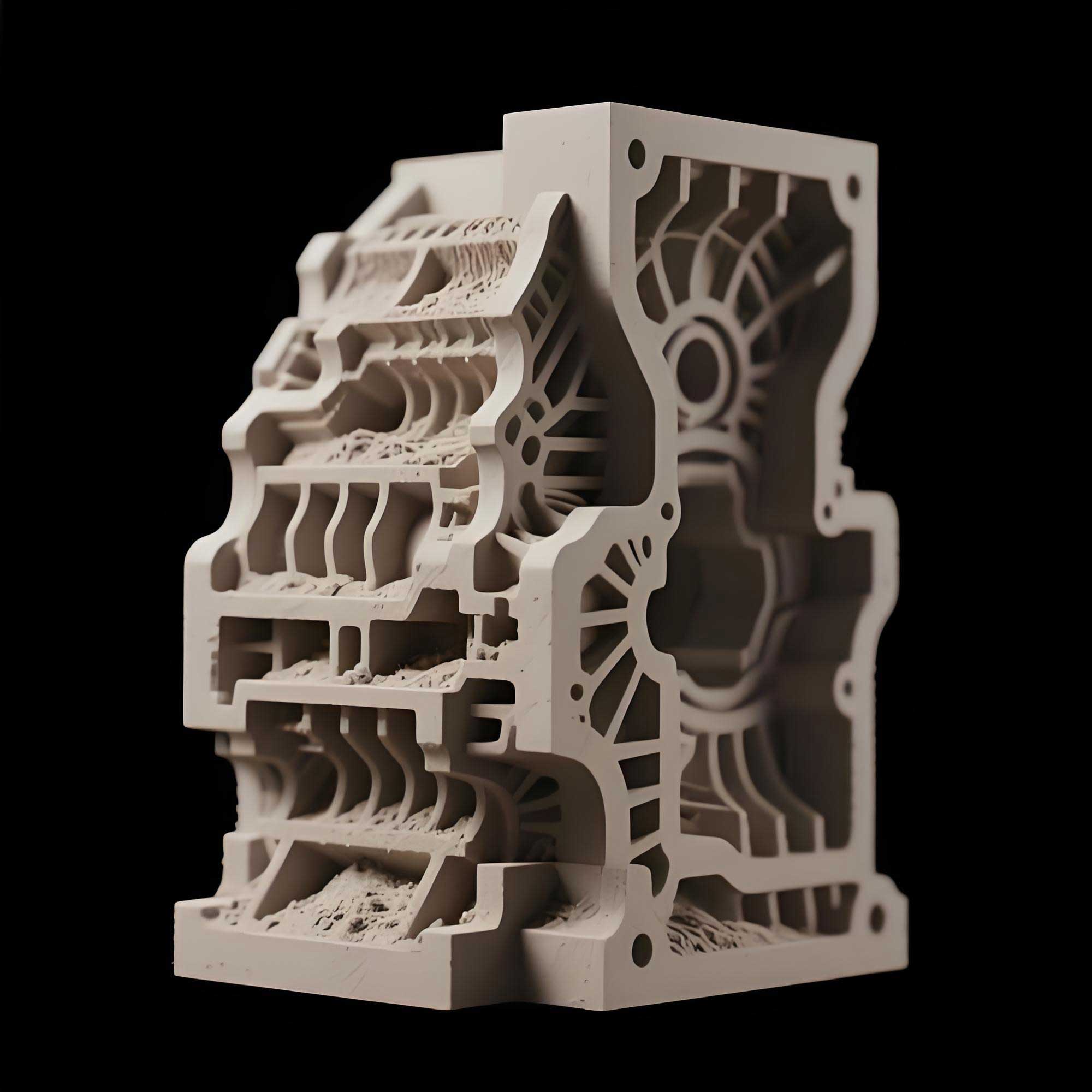
The fundamental principle of 3D sand printing for casting involves the application of rapid prototyping technology to the traditional resin sand casting process. I will explain the workflow in detail: first, a casting mold CAD model is derived from the part CAD model. The casting mold CAD model is then processed to generate an STL file, which is subsequently sliced into cross-sectional layers. These layered profiles generate the control information necessary for printing. During the molding process, the catalyst is uniformly mixed with virgin sand. The printhead then precisely jets the binder according to the cross-sectional profile of each layer. The binder undergoes a cross-linking reaction with the catalyst, causing the sand to solidify layer by layer, building up the mold form. The sand that is activated by both the binder and catalyst becomes consolidated, and once one layer solidifies, the next layer is bonded on top. After all layers are bound, a spatial entity is obtained. In areas where the binder has not been jetted, the sand remains loose, which facilitates easy removal. By cleaning out the uncured loose sand from the interior, a casting mold with a specific wall thickness is obtained. After applying or dipping a coating onto the surface of this mold, it is ready for metal pouring. The underlying principle is clearly illustrated in my process descriptions and is fundamental to understanding how this technology operates.
3. Detailed Process Flow
The complete 3D sand printing process, which I will outline step-by-step, begins with three-dimensional CAD design to obtain the part drawing. From there, the casting drawing is designed, followed by the casting mold model. The geometry is then converted to the STL graphics format. The next step involves layered slicing to derive the print layers. Following this, the sand mold is printed. I then describe the post-processing steps: cleaning loose sand from the mold surface, applying coatings, oven drying, closing the molds, pouring metal, cleaning the casting, and finally inspecting the casting. The entire process flow can be represented as follows:
CAD 3D design → Casting design → Mold model design → STL conversion → Layer slicing → Sand mold printing → Sand cleaning → Coating → Drying → Mold closing → Pouring → Casting cleaning → Casting inspection
4. Comparative Analysis: 3D Sand Printing vs. Traditional Molded Processes
In my analysis, I systematically compared 3D sand printing technology with traditional molded processes. Table 1 summarizes the key differences that I have identified through practical application of both technologies.
| Aspect | 3D Sand Printing (PCM) | Traditional Molded Process |
|---|---|---|
| Production Process | No mold required; direct printing of the mold | Requires pattern/mold fabrication |
| Development Cycle & Cost | Short product development cycle, approximately 3-5 days, lower total production cost | Longer cycle due to pattern making; higher cost for small batches |
| Worker Skill Requirements | High automation; operators require standard skills; only one week of training is needed | Requires skilled pattern makers and molders |
| Work Environment | Low emission of harmful substances; environmentally friendly; aligns with green foundry policies | Higher emissions from pattern making and molding; more environmental concerns |
| Process & Manufacturing Flexibility | Core and mold can be printed as a single integrated unit, reducing assembly errors; no draft angle needed; castings are closer to design intent; reduced casting weight and machining allowance; no constraints on demolding structure; can produce molds of arbitrary shape; high flexibility; easy design modifications with few reproduction constraints | Requires draft angles; limited by demolding constraints; less geometric flexibility |
5. Main Performance Characteristics of 3D Sand Printers
5.1 Composition of a 3D Sand Printer System
In my work with these systems, I have found that a typical 3D sand printer consists of several key components. I will classify them as follows: the main machine, auxiliary material preparation equipment, graphic slicing software, sand mold cleaning devices, and post-processing equipment. The main printer host includes the machine frame, sand feeding mechanism, sand spreading device, X and Y-axis scanning mechanisms, Z-axis lifting system, build box, box conveying device, print control system, motion control system, and electrical cabinet. Auxiliary material preparation equipment consists of mixing and feeding devices for new sand, reclaimed sand, mixed new and reclaimed sand, catalyst, and additives, along with the conveying systems. The graphic slicing software includes STL file repair, size compensation, and slice layering modules. Sand cleaning equipment includes devices for cleaning the mold, robots, dust collection, and loose sand collection systems. Post-processing supporting equipment includes coating spray or dip machines, drying ovens, and similar tools.
5.2 Key Performance Indicators
To enable users to make informed decisions, I have identified the following critical performance indicators that should be evaluated when comparing 3D sand printers:
| Indicator | Description | Typical Units / Values |
|---|---|---|
| Maximum Print Size | The maximum length, width, and height dimensions of the sand mold that can be printed within the build box. | Millimeters (mm) |
| Printhead Type & Specification | Categorized by the volume of jetted droplets and the number of nozzles. Common nozzle counts include 256, 512, 1024. Internationally, 512 is common; domestically, 1024 is more prevalent. The Dimatix brand (a Fujifilm company) is the mainstream choice among major manufacturers. | Nozzle count (e.g., 256, 512, 1024) |
| Layer Thickness | The thickness of each slice produced by the slicing software. Thicker layers increase efficiency but result in more visible layer lines. Thinner layers produce better surface finish but lower efficiency. | Micrometers (μm) or millimeters (mm) |
| Dimensional Accuracy | The deviation between the printed sand mold geometry and the theoretical 3D model value. This is influenced by mechanical motion accuracy, sand grain size, and binder diffusion. | Millimeters (mm) or ± value |
| Print Speed | The average time required to complete each layer (including sand feeding, spreading, printing, and related auxiliary actions). | Seconds per layer (s/layer) |
| Build Rate | The volume of sand mold produced per hour of continuous operation. | Liters per hour (L/h) |
| Print Resolution | The number of dots that can be printed per square inch in both X and Y directions. | Dots per inch (dpi) |
| Tensile Strength | The tensile strength of a standard ‘8’ shape test specimen printed using the process. | Megapascals (MPa) |
| Gas Evolution | The amount of gas generated when the sand mold burns at a specific temperature. | Milliliters per gram (mL/g) |
| Permeability | The efficiency with which gas passes through the sand mold after pouring. | Permeability units |
The build rate can be expressed by the following formula that I have validated through practical testing and application:
$$\text{Build Rate} = \frac{\text{Max Layer Volume}}{\text{Time per Layer}}$$
Alternatively, in units of liters per hour:
$$\text{Build Rate (L/h)} = \text{Layer Volume (L)} \times \frac{3600}{\text{Time per Layer (s)}}$$
6. Framework for Machine Selection Analysis
In my professional assessment, users should carefully evaluate several factors when selecting a 3D sand printer, integrating their specific business context with the technical capabilities of the equipment. I have structured the selection criteria as follows.
6.1 Evaluating Efficiency Metrics
It is critical to recognize that a 3D sand printer serves as both a production tool and a capital asset investment. The decision-making process must involve a thorough evaluation and comparison of the key performance indicators of printers from different manufacturers. Special attention should be focused on print speed, as it directly dictates efficiency and production output, which in turn helps to amortize manufacturing costs. Higher production volume translates to increased profitability. Therefore, print speed, build rate, and operational stability are the most critical selection parameters.
6.2 Evaluating Economic Indicators
From a cost perspective, I will now detail the economic considerations. The design of the printer should ideally accommodate consumables of varying quality levels to reduce usage costs and provide flexibility in material selection.
- Consumables Compatibility: The printer should support the use of domestically produced sands and be compatible with different grades of sand. It is preferable to source sand locally to minimize transportation costs. I distinguish between two main types of sand used in printing:
- Natural silica sand: generally sufficient for medium and low-end casting quality requirements.
- Synthetic sand (e.g., ceramic sand, cerabeads): recommended for high-end, complex products.
- Consumables Saving Features: Printers that are designed to minimize waste effectively create value for the user. I recommend evaluating whether the printer and its system include the following features:
- Automatic collection and in-line recycling of excess sand from the spreading process (saving catalyst).
- Reclamation and reuse of used sand.
- Minimal founding layer thickness for the initial printing setup (reducing preparatory material usage).
- Localized printing capabilities for smaller parts on a larger machine.
- Maintenance Costs: The most significant ongoing maintenance cost is the printhead. The industry predominantly uses low-nitrogen furan resin as the printing binder, which presents compatibility challenges with printheads under current technology, impacting printhead lifespan. Some have used phenolic resin, but its stability is lower, and its properties can be even more detrimental to printheads than furan resin. Inorganic binders represent the strategic direction for the industry due to their environmental friendliness, low corrosiveness, and excellent casting performance. Some leading domestic 3D printing enterprises have already overcome technical challenges in this area, and inorganic binder solutions are expected to reach the market soon. While integrating multiple printheads can increase the jetting width and improve efficiency, this also raises the overall cost associated with printhead maintenance and replacement. Simply increasing the number of printheads is not always the best solution. Consequently, manufacturers must improve their design to balance high print efficiency with lower maintenance costs, offering users a win-win scenario.
6.3 Evaluating Operational Convenience
Regarding the operational aspects of the printer, I have identified several key features that enhance user experience and reduce operational complexity:
- High Automation: The higher the degree of automation, the lower the skill barrier for operators. Ideally, ordinary workers should be able to operate the machine after minimal training, which also reduces labor costs.
- Fast Selection and Switching of Print Parameters: Different cast metals require different sand types and mold strengths, which affect the dosages of catalyst and binder. Casting quality requirements influence the grade of sand used, and print speed, layer thickness, and resolution. These parameters form complex combinations. An intuitive interface that allows for quick selection, storage, and switching between optimal process parameter sets is highly beneficial, reducing the need for specialist intervention and minimizing downtime and material waste. Users should consider printers that offer simple and fast parameter switching.
6.4 Evaluating Special Functional Requirements
Users with unique product requirements may require features beyond standard offerings. For example, enterprises in the research sector might not require high-throughput production printers. I recommend that these users communicate openly with manufacturers about their needs, which might include functions such as localized printing (running a small job on a large machine) or localized enhanced printing (increasing printing strength for small, delicate structures).
6.5 Aligning Selection with Production Scale
In my experience, users should align the size and type of printer with their specific production scale:
- High-Volume Production: For companies dealing with large-scale components, where print demand is high and the goal is to replace traditional foundry methods with 3D printing as part of an intelligent production line, adopting a smart workshop model is advisable.
- R&D and Small-Batch: For enterprises focused on R&D of complex samples, or for multi-variety, small-batch production, a single, flexible 3D printer integrated with traditional casting processes is more suitable.
6.6 Evaluating Manufacturer Brand and Comprehensive Strength
Since 3D sand printers are relatively new and non-standardized equipment, the industry lacks uniform standards. Although the technology has been developing within the country for over two decades, significant design differences exist among manufacturers, and technology updates are frequent. Maintenance and repairs often depend heavily on the original manufacturer. Therefore, I strongly advise selecting printers from manufacturers with significant size, strong R&D capabilities, proprietary technology patents, brand recognition, and the resilience to withstand long-term business cycles. This ensures long-term viability for after-sales service and support.
7. Specifying the Printer Size (Build Volume)
To determine the optimal printer specification, users must first audit and evaluate their product portfolio. The user should identify the representative characteristics of their product range and calculate the corresponding casting mold dimensions. By analyzing the statistical distribution of these mold sizes, the user can identify the required printer specification, which is the maximum length, width, and height of the sand mold that the build box can accommodate. The chosen specification must cover the vast majority of the dimensions of the enterprise’s own products.
For example, if a user’s products have mold dimensional requirements that statistically fall within the ranges shown below, the printer specification must be chosen to encompass these limits.
| Product Group | Prevalent Mold Width Range (mm) | Prevalent Mold Length Range (mm) | Prevalent Mold Height Range (mm) | Required Print Volume (W x L x H in mm) |
|---|---|---|---|---|
| Small Brackets | 200-300 | 200-400 | 100-200 | 300 x 400 x 200 |
| Pump Housings | 400-500 | 400-600 | 200-400 | 500 x 600 x 400 |
| Engine Blocks | 600-800 | 800-1000 | 400-600 | 800 x 1000 x 600 |
Based on this analysis, a user whose portfolio includes all three product groups would require a printer with a minimum build volume of 800 mm x 1000 mm x 600 mm.
8. Estimating Sand Mold Production Capacity
To calculate the potential production output of a selected 3D sand printer, I use a systematic approach. The first step is to calculate the time required to print one full build box (one job). This is given by the following formula:
$$\text{Print Time per Job (hours)} = \frac{\text{Total Print Height (mm)}}{\text{Layer Thickness (mm)}} \times \frac{\text{Time per Layer (seconds)}}{3600}$$
Next, calculate how many jobs or boxes can be printed per day:
$$\text{Number of Jobs per Day} = \frac{\text{Operating Hours per Day}}{\text{Print Time per Job (hours)}}$$
This calculation is followed by determining the total volume of the build box:
$$\text{Build Box Volume (L)} = \frac{\text{Box Width (mm)} \times \text{Box Length (mm)} \times \text{Box Height (mm)}}{1000000}$$
After this, I consider the yield of usable sand molds within a single build box. The user must estimate this based on the actual geometry of their parts. The sand mold yield ratio is defined as the volume of the useful sand mold relative to the total volume of the build box. This ratio is then used to calculate the effective sand mold volume per box:
$$\text{Effective Sand Mold Volume per Job (L)} = \text{Build Box Volume (L)} \times \text{Sand Mold Yield Ratio (\%)}$$
If the weight of the sand mold is required, this volume can be multiplied by the density of the sand. Finally, the total daily sand mold production can be calculated:
$$\text{Daily Sand Mold Production (L)} = \text{Number of Jobs per Day} \times \text{Effective Sand Mold Volume per Job (L)}$$
To estimate the daily production of castings, the user must also factor in the ratio of sand mold volume to casting weight. This ratio is often expressed as a sand-to-metal ratio. I use the following formula to determine this:
$$\text{Daily Casting Production (kg)} = \frac{\text{Daily Sand Mold Production (L)}}{\text{Sand-to-Metal Ratio (L/kg)}}$$
or alternatively, if the sand-to-metal ratio is provided on a weight basis, the calculation is adjusted accordingly.
9. Concluding Remarks
Based on my extensive analysis, I have arrived at the following conclusions:
- Superior Value in Specific Applications: I have found that 3D sand printing offers significant application value in new product development, single-piece or small-batch production, and complex high-end casting products. It effectively shortens development cycles and minimizes the investment in various R&D-related costs. The advantages are clear and highly evident.
- Informed Equipment Selection is Crucial: Enterprise users of 3D sand printing technology must carefully select the appropriate machine model and brand (manufacturer) based on the specific characteristics of their own products. A one-size-fits-all approach is ineffective, and the evaluation framework I have outlined provides a structured guide for this decision.
- Mature Technology: The process and application of 3D sand printing for casting are already mature. Both domestic and international examples show numerous success stories in prototypes, new product R&D, and across various mechanical manufacturing sectors. The viability of the process is not in question. The technology is a robust, reliable, and strategically important tool for modern foundries.