
In this work, I present a comprehensive research on casting process design methods based on sand 3D printing technology. The traditional foundry industry is facing increasing pressure to reduce pollution, energy consumption and cost while improving quality and flexibility. Sand 3D printing, also known as binder jetting or selective laser sintering in sand mold applications, offers a revolutionary route for designing and fabricating sand molds directly from CAD models without any pattern or core box. This unique capability frees the casting designer from many long‑standing constraints such as draft angles, parting line limitations, and the need for expensive tooling. My objective is to establish a set of design principles that fully exploit the geometric freedom of sand 3D printing, and to validate these principles through a detailed case study of a bronze tripod casting.
1. Introduction
Casting is one of the most important manufacturing processes for producing metal components. However, conventional sand casting relies heavily on patterns, core boxes, and molding equipment, which are expensive and time‑consuming to produce, especially for single or small‑batch production. In recent years, the globalization of markets and stricter environmental regulations have forced foundries to adopt more efficient, clean and flexible technologies. Additive manufacturing, particularly sand 3D printing, has emerged as a promising solution because it can directly create sand molds and cores layer by layer without physical tooling. The two main technical routes are three‑dimensional printing (3DP) and selective laser sintering (SLS) of sand. The 3DP method uses an array of printheads to selectively deposit a binder onto a bed of sand pre‑mixed with a catalyst, while the SLS method uses a laser to melt the binder coating on resin‑coated sand. Both methods allow the fabrication of complex internal channels, undercuts, and free‑form surfaces that are impossible or very difficult to achieve by conventional molding.
Although many studies have focused on the hardware and process parameters of sand 3D printing, there is still a lack of systematic design methodology that translates the capabilities of this technology into practical casting process design. Therefore, my research aims to fill this gap by analyzing the characteristics of sand 3D printing, deriving a set of design principles, and demonstrating them on an art casting – a bronze tripod. I used SolidWorks for 3D modeling and ProCAST for numerical simulation of filling and solidification. The optimized process was then determined by comparing several designs and evaluating predicted defects.
2. Overview of Sand Mold 3D Printing
Sand mold 3D printing is an additive manufacturing process that builds sand molds directly from a three‑dimensional CAD model. The workflow begins with creating the mold geometry as an STL file, which is then sliced into thin layers. The printer spreads a thin layer of sand (typically silica sand mixed with a curing agent or a binder) and selectively bonds the sand by jetting a liquid binder or by scanning a laser over the predefined cross‑sectional areas. After each layer is completed, the build platform descends and a new layer is spread. This process repeats until the entire mold volume is formed. The unbound sand acts as support, which eliminates the need for separate supports and enables the creation of truly free‑from geometries. After the printing is finished, the operator must remove the loose sand from the internal cavities and clean the mold surface. A typical sand mold print layer thickness ranges from 0.2 mm to 0.5 mm, and the resolution can reach about 0.1 mm per 100 mm.
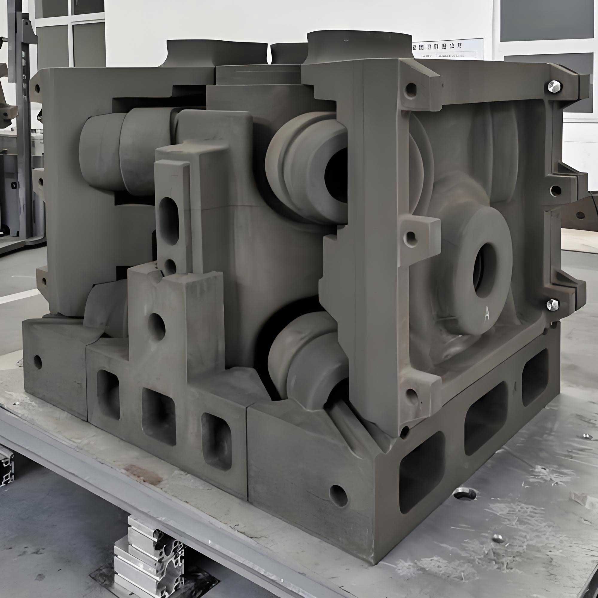
The main advantage of sand 3D printing compared with conventional molding is that it eliminates the need for patterns and core boxes. This dramatically shortens the lead time for new product development, often by 50–80%. It also reduces the cost for small batches and one‑off castings. The technology enables the construction of molds with curved sprues, complex gating, and spherical risers because draft is no longer necessary. Moreover, it allows the integration of cores and mold bodies into a single piece, which reduces assembly errors. However, the strength of printed sand molds is generally lower than that of mold‑made resin sand molds, and the surface finish may be coarser. In my study, I used a furan resin binder system and 70/140 mesh silica sand, whose properties are adequate for bronze casting.
3. Design Principles Based on Sand 3D Printing
In conventional sand casting, the mold design is strongly constrained by the need to withdraw the pattern from the mold. This forces drafts, straight sprues, planar parting lines, and a limited choice of riser shapes. Sand 3D printing removes most of these constraints, but the designer must consciously exploit this freedom. Below I summarize the principles that have guided my work.
3.1 Gating System Design
Sprue design. In conventional horizontal casting, straight sprues are required to allow pattern withdrawal. A straight sprue allows the molten metal to accelerate under gravity, causing turbulent flow and aspiration of air. With sand 3D printing, a curved or serpentine sprue can be easily produced even in a horizontally parted mold. A curved sprue reduces the pressure head and creates a more controlled flow. Figure below shows the difference between straight and curved sprues.
To quantify the effect, I performed a simulation comparing a straight sprue and a curved sprue of the same total height. The inlet velocity at the bottom was 1.6 m/s for the straight sprue, while for the curved sprue it was only 1.2 m/s. The pressure at the sprue well was 1.14 MPa for the straight design and 1.03 MPa for the curved design. This clearly demonstrates that curved sprues reduce impact and splashing, thereby minimizing sand erosion and gas entrapment.
Runner and ingate positioning. In conventional two‑part molding, the runners and ingates must be placed on the parting plane so that the pattern can be removed. In sand 3D printing, the ingates can be placed anywhere on the mold cavity. This is particularly beneficial for tall castings where a middle or stepped gating system can be designed without the need for a third molding box or complex core. For example, a step‑gating system can have the lower ingates near the bottom of the cavity and the upper ingates at a higher level, all within the same two‑part mold. This improves the temperature distribution and helps achieve directional solidification. The design freedom also allows the ingates to be located away from critical aesthetic surfaces or machined areas, thus avoiding defects in those regions.
Gating ratio. The cross‑sectional area ratios of the sprue, runner, and ingate determine whether the gating system is pressurized or non‑pressurized. For bronze alloys, open systems with a ratio of \(A_{sprue}:A_{runner}:A_{ingate}\) around 1:2:3 are recommended. In my design for the bronze tripod, I adopted an open system with \(A_{sprue}:A_{runner}:A_{ingate} = 1:1.9:2.7\). The total sprue area was 12.56 cm² (one 40 mm diameter sprue), the runner area was 24 cm² (four runners each 6 cm²), and the total ingate area was 34 cm² (seven ingates). This ratio gave a smooth filling behavior without excessive pressure.
| Component | Number | Area (cm²) | Cross-section (mm) |
|---|---|---|---|
| Sprue | 1 | 12.56 | Ø 40 |
| Runner | 4 | 6 each (24 total) | 30 × 20 |
| Upper ingates | 4 | 4 each (16 total) | 20 × 20 |
| Lower ingates | 3 | 6 each (18 total) | 30 × 20 |
3.2 Riser Design
The most important requirement for a riser is that it must remain liquid longer than the casting region it feeds. The cooling rate of a riser is inversely proportional to the ratio of its surface area to its volume. Therefore, for a given volume, the riser should have the smallest possible surface area. The sphere is the shape that minimizes surface area for a given volume. In conventional sand molding, spherical risers are extremely difficult to form because of pattern withdrawal. In sand 3D printing, this limitation is removed. The volume of a sphere is:
\[
V = \frac{4}{3}\pi R^3
\]
and its surface area is:
\[
A = 4\pi R^2
\]
For a given volume \(V\), we can calculate the surface area of the spherical riser as:
\[
A_{sphere} = (36\pi)^{1/3} V^{2/3}
\]
For comparison, the surface areas of a hemispherical‑top cylinder riser and a plain cylindrical riser are calculated in Table 1 for equal volumes. It is evident that the sphere has the minimum surface area and therefore the best insulating performance. In my bronze tripod design, I therefore adopted a spherical blind riser placed above the thick ear region of the casting.
| Riser type | Surface area | Ratio to sphere |
|---|---|---|
| Sphere | \((36\pi)^{1/3}V^{2/3}\) | 1.00 |
| Hemispherical‑top cylinder | \(2V/a + 5\pi a^2/3\) | >1 |
| Cylinder | \(2V/r + 2\pi r^2\) | >1 |
Additionally, a spherical riser can be connected to the casting through a small cylindrical neck. This neck can be designed with a reduced diameter to facilitate easy removal after solidification. In sand 3D printing, the neck can be shaped with a slope or a narrow groove to create a stress raiser that enables clean breaking.
3.3 Mold Structure Design
Core and mold integration. In conventional casting, internal cavities are formed by separate cores that must be manufactured in core boxes and then installed into the mold. This process requires core boxes, core making equipment, and handling operations, which add time and cost and often introduce dimensional errors. Sand 3D printing allows the core to be printed as an integral part of the mold. For example, a hollow cylinder can be produced with the core already connected to the mold body through thin supports that will later be removed. This reduces the number of parts and eliminates assembly tolerances. For complex sand cores that traditionally require assembly of multiple core pieces, sand 3D printing can produce the entire core as one piece, avoiding joints that could cause fins or shifts.
Wall thickness. Conventional molds are contained in a flask or a box, so the thickness of the mold wall is often determined by the flask size, leading to unnecessary material usage. Sand 3D printing allows wall thickness to be designed precisely based on the mechanical strength required to withstand the metallostatic pressure and the thermal loads. The functional wall is the layer of sand that separates the cavity from the outside or from a hollow support structure. Any material beyond the required thickness is unproductive. I have derived simplified formulas for estimating the minimum wall thickness for horizontal and vertical walls under static loading. For a horizontal wall subjected to a uniform pressure \(p\), the bending stress must not exceed the allowable strength:
\[
\sigma = \frac{3 p L^2}{4 T^2} \le \sigma_{allow}
\]
which can be rearranged to give the minimum thickness \(T\) as:
\[
T \ge \sqrt{\frac{3 p L^2}{4 \sigma_{allow}}}
\]
where \(L\) is the width of the wall and \(\sigma_{allow}\) is the allowable stress of the printed sand. A similar relationship exists for vertical walls, where the pressure varies linearly with height. By using these formulas and verifying them through finite element analysis, I was able to design the mold wall thickness for the bronze tripod to be just 30 mm, except at locations where a thicker section was needed for strength.
Mold wall structure. Beyond the minimum thickness, the mold wall can be designed with local features to control heat transfer. For example, a hot spot on a casting can be eliminated by locally reducing the mold thickness or creating a hollow pocket behind the hot spot, which increases the cooling rate. Conversely, a thick wall may be desired to act as a pad for feeding. Sand 3D printing allows the incorporation of internal channels for air cooling or for the placement of insulating materials. In my work on a thin‑plate steel casting, I demonstrated that adding a rectangular cavity inside the mold behind the hot spot shifted the solidification pattern and eliminated shrinkage defects. The simulation results showed that with the cavity, the defect disappeared and the temperature distribution became more uniform.
3.4 Parting Surface
In conventional molding, the parting line is usually a planar surface because the pattern must be withdrawn along a straight path. Sand 3D printing permits non‑planar parting surfaces, because the mold is printed in separate pieces that can be joined along any three‑dimensional surface. This gives the designer the freedom to orient the casting in the mold such that critical features are placed in a favorable position. For example, a thin and large flat plate is difficult to fill with conventional horizontal parting because the metal has to travel a long distance before reaching the extremities. By using an inclined parting surface, the cavity can be tilted so that the metal flows downward into the plate, reducing the travel distance and preventing cold shuts. In the bronze tripod design, I used a slightly inclined top surface to orient the three legs downward, ensuring complete filling of the thin legs.
3.5 Placement of Mold Blocks in the Printer Sand Bed
When printing several sand blocks in one build job, their placement in the printer’s build box affects the printing time and the surface quality of the parts. The printing time is proportional to the height of the stack because the printer spreads each layer over the entire build area. Therefore, the blocks should be arranged so that the maximum height is minimized. They should also be packed as densely as possible to use the available volume efficiently. Typically, there is no need to avoid contact between blocks because they can be separated after printing. However, one should consider that printed parts shrink or distort very little, but the unbound sand between blocks facilitates separation.
Surface quality of printed sand depends on the orientation of the surface with respect to the printing layers. A curved surface that is vertically oriented will exhibit a staircase effect because each layer has a step-like profile. To minimize this effect, curved surfaces should be oriented horizontally in the build bed, so that the curvature is formed by the lateral resolution of the printer rather than by the layer steps. Conversely, a flat inclined surface should be oriented vertically, so that the surface lies parallel to the printing direction. In this way, the surface appears smoother. In the design of the bronze tripod mold, I oriented the cylindrical surfaces horizontally in the build box, while the inclined surfaces were placed vertically.
4. Case Study: Bronze Tripod
4.1 Casting Analysis
The selected part is a bronze tripod, a classic art casting. The technical requirements are:
- Material: C90300 tin bronze according to ASTM B584-2014.
- The surface must be free from cold shuts, cracks, shrink holes, penetration defects.
- Misruns, fins and shifts must be corrected to a smooth transition.
- All castings must be cleaned; gates and risers should be removed flush with the surface.
The tripod is 410 mm high, with a maximum outside diameter of 309 mm and a weight of 33 kg. The wall thickness ranges from 5 mm to 34 mm. The casting has three hollow legs and two ring-shaped ears. The intricate patterns on the surface represent a challenge for conventional molding because the pattern would need very complex core boxes. The bottom of the legs is relatively thick, and the connection between the body and the legs is a hot spot. The design of a suitable feeding system is therefore critical.
4.2 Material Properties
C90300 tin bronze has good castability, corrosion resistance and attractive coloring properties. Since the ProCAST database does not include this alloy directly, I entered the chemical composition (Cu bal., Sn 7.5–9%, Zn 3–5%, Ni 1%, Pb 0.3%, Fe 0.2%) and used the Scheil model to compute the thermophysical properties. The computed properties are listed in Table 2.
| Property | Value |
|---|---|
| Thermal conductivity | 71.8 W/(m·K) |
| Density | 8.2 × 10³ kg/m³ |
| Liquidus temperature | 1003 °C |
| Solidus temperature | 633 °C |
| Latent heat | 365.9 kJ/kg |
| Linear expansion coefficient | 1.2 × 10⁻⁵ K⁻¹ |
These values were used to define the metal in the simulation. The casting was poured at 1150 °C, which is about 150 °C above the liquidus, to improve the fluidity of the thin sections.
4.3 Molding Materials
The selection of sand and binder is crucial for the strength and permeability of the printed mold. I selected 70/140 mesh silica sand (according to GB/T 9442), furan resin binder, and p-toluene sulfonic acid as catalyst. The sand/resin/catalyst ratio was adjusted to achieve a tensile strength of about 1.0 MPa, which is sufficient for handling and pouring. The surface of the mold cavities was coated with an alcohol‑based alumina‑silicate refractory coating to prevent metal penetration and provide a smooth surface on the casting. The coating parameters are given in Table 3.
| Property | Value |
|---|---|
| Refractoriness | ≥1770 °C |
| Fineness | 320 mesh |
| Al₂O₃ content | 91.84% |
| SiO₂ | 3.11% |
| TiO₂ | 2.67% |
| Fe₂O₃ | 0.59% |
| CaO | 0.70% |
| MgO | 0.50% |
| Ignition loss | 0.32% |
4.4 Initial Process Design
Because the tripod has thin walls and a relatively complex shape, the casting must be poured with a well-designed gating system. I decided to use an open gating system to ensure laminar filling. The first design was a middle injection system, where the metal enters at the middle of the cavity. However, simulation showed that the flow through the ingates could entrap air at the connection between the ingate and the casting. Therefore, I developed a second design, a stepped open gating system, which introduces metal both at the lower part and at the upper part of the cavity. This design avoids air entrapment and promotes good thermal gradients.
In the stepped system, the sprue is located at the center of the three legs. Four runners distribute the metal to seven ingates: four upper ingates (20 mm × 20 mm) and three lower ingates (30 mm × 20 mm). The total gating ratio is \(A_{sprue}:A_{runner}:A_{ingate} = 1:1.9:2.7\). The sprue diameter is 40 mm. The pouring time was determined using the empirical formula:
\[
\tau = S_1 \sqrt{m}
\]
where \(m\) is the total mass of metal in the mold and \(S_1\) is a coefficient depending on wall thickness. For a wall thickness of 5–10 mm, \(S_1 = 2.2\). With a metal mass of 42 kg, the theoretical pouring time was 16.3 s; however, the required minimum rising speed of the metal level in the mold must be greater than 3.0 cm/s. From the average rising speed:
\[
v_L = \frac{C}{\tau}
\]
where \(C\) is the cavity height (48.6 cm). For \(\tau = 16.3\) s, \(v_L = 2.98\) cm/s, which is slightly below the recommended value. Therefore, I reduced the pouring time to 12 s. The resulting average rising speed is 4.05 cm/s, which is acceptable.
The height of the sprue and the pouring cup were checked by the pressure angle condition:
\[
H_M \ge L \tan \alpha
\]
where \(L = 154\) mm is the horizontal distance from the sprue axis to the farthest point of the cavity, and \(\alpha\) is the pressure angle (less than 20°). The calculated value is satisfied because the actual height of the sprue above the ingates is about 200 mm.
4.5 Simulation of Filling and Solidification
I imported the CAD model into ProCAST and generated a finite element mesh. The total number of volume elements for the stepped gating system was about 3.34 million. The mold material was defined as furan resin sand with initial temperature 25 °C. The casting material was C90300 bronze with an initial temperature of 1150 °C. The heat transfer coefficient between the metal and the sand mold was set to 500 W/(m²·K), and the mold outer surface was exposed to air at 25 °C with a heat transfer coefficient of 10 W/(m²·K). The gravity vector was oriented downward along the pouring direction.
The filling simulation showed that the metal flowed smoothly through the curved sprue and runners, filling the lower part of the cavity first and then rising progressively. The maximum velocity inside the cavity stayed below 0.5 m/s, which is considered safe for sand molds. No cold shut or mistun was predicted. The solidification simulation predicted that the solidification sequence proceeds from the bottom legs upward to the top of the casting. However, the thick ear regions remained liquid for a long time, and the simulation predicted shrinkage porosity in the ears because they were isolated from the feed metal. The Niyama criterion clearly indicated shrinkage defects in the ear area.
4.6 Optimization with Riser Designs
To eliminate the shrinkage in the ears, I compared four alternatives:
- Enlarging the vent holes above the ears to accelerate cooling.
- Adding an open riser above each ear.
- Adding a cylindrical blind riser with a hemispherical top.
- Adding a spherical blind riser with a small neck.
Each variant was simulated. The open riser helped some but created a hot spot at the junction between the riser and the casting because the open riser cooled too quickly at its top. The cylindrical blind riser performed better, but the spherical blind riser gave the best results because its surface area for a given volume is minimal. The final design uses a spherical blind riser with a neck diameter of 22 mm. This riser solidifies after the casting ear, providing excellent feeding. The simulation of the optimized design showed no shrinkage porosity in the casting, and the riser neck could be easily removed by machining or hammering.
4.7 Final Optimized Process
After iterative simulation, the optimum casting process parameters were determined as follows:
| Parameter | Value |
|---|---|
| Net casting weight | 33 kg |
| Gross casting weight (with gating) | 44 kg |
| Total metal weight poured | 50 kg |
| Process yield | 75% |
| Molding method | Sand 3D printing |
| Sand and binder | 70/140 mesh silica sand, furan resin, p-toluene sulfonic acid |
| Coating | Alcohol-based alumina-silicate refractory coating |
| Gating ratio (sprue:runner:ingate) | 1 : 1.9 : 2.7 |
| Pouring temperature | 1150 °C |
| Melting/furnace temperature | 1200 °C |
| Pouring time | 12 s |
| Cooling time before shakeout | 1050 s |
| Total solidification time | ~890 s |
4.8 Mold Block Design for the Bronze Tripod
Since the tripod has no undercuts that would prevent pattern withdrawal in conventional molding, the entire mold can be printed in several blocks for easier handling and coating. I compared three block configurations.
Scheme 1: The mold is split into three pieces: an upper piece (including the core for the inside of the body), and two lower half-pieces. However, the hollow legs are then difficult to coat because the core is integral.
Scheme 2: The lower part is divided into three segments, and the leg cores are printed separately as loose pieces. This allows coating of all surfaces but introduces an assembly step.
Scheme 3: The entire mold is split into five blocks: one upper block (containing the pouring cup, sprue, and the upper part of the cavity), three lower blocks (each containing one leg), and the core for the body interior. This configuration enables coating and easy handling while keeping the number of parts to a minimum. The core is printed with the body block as an integral unit, except for the three leg cores, which are separate to permit coating. In the final design, I used the third scheme. The blocks are joined using a tapered circular tenon-mortise arrangement with a 10° taper, which significantly increases the lateral strength of the assembled mold. The assembly is held together by a simple metal band.
The mold blocks are printed separately on the same build job. Their spatial arrangement in the printer sand bed was optimized to reduce the total height. The blocks were stood on their ends so that the curved surfaces were horizontal, thereby minimizing the staircase effect on the exterior. The loose sand between the blocks was removed after printing, and the blocks were then coated and assembled.
4.9 Melting and Post-Processing
The C90300 alloy was melted in a 0.5-ton medium frequency induction furnace. Copper and nickel were charged first, melted, and superheated to about 1200 °C. Phosphorus copper was then added for deoxidation, followed by zinc, tin and lead. An oxidizing flux was used to reduce gas content. The melt was poured at 1150 °C. After pouring, the mold was allowed to cool for about 20 minutes before shakeout. The casting was cleaned by abrasive blasting, and the gates and risers were cut off. The surface was ground and polished, then colored using an artistic finishing process.
5. Conclusion
In this work, I have presented a systematic methodology for casting process design based on sand 3D printing. The main conclusions are:
- Sand 3D printing allows the use of curved sprues, which reduce metal velocity and pressure at the sprue well, leading to smoother filling and fewer defects such as air aspiration and sand erosion.
- Runners and ingates can be placed at any location on the mold cavity, enabling middle or stepped gating without a third part. This improves the thermal distribution and feeding efficiency.
- Spherical risers are the optimal shape for feeding because they have the minimum surface area per unit volume. The technology eliminates the draft restriction, making spherical risers practical.
- The mold wall thickness and structure can be functionally optimized. Unnecessary material can be removed to reduce cost and improve cooling, while local wall thinning can eliminate hot spots.
- Complex cores can be printed as a single unit, either integrated with the mold or as separate pieces, reducing assembly time and errors.
- Non-planar parting surfaces permit inclined placement of the casting, which is beneficial for filling large flat plates or long thin sections.
- When multiple sand blocks are printed in one build, they should be arranged compactly and oriented to minimize height and staircase effect.
The bronze tripod case study demonstrated the entire design flow. Starting from two initial gating schemes, I used ProCAST to identify potential defects and then optimized the process by adding a spherical blind riser. The final process achieved a defect-free casting with a process yield of 75%. Compared with the traditional approach of welding six separate castings together, the sand 3D printing approach enabled integral casting of the whole tripod, with improved dimensional accuracy and surface quality. This methodology can be generalized to other art castings and to complex engineering castings, providing a powerful design tool for the foundry industry.