
As a casting engineer focused on the development of complex components, I have been deeply involved in the production practice of narrow channel impellers using 3D sand printing technology. This article presents my direct experience in designing, simulating, and manufacturing a narrow channel impeller with 3D sand printing, emphasizing the advantages of this approach over conventional molding methods. The work covers the technical requirements of the impeller casting, the development of two different casting process plans, the 3D printed sand mold design, numerical simulation of mold filling, and the final validation through actual pouring. Throughout the entire process, 3d sand printing played a central role, enabling rapid tooling-free fabrication of complex sand cores and molds, which greatly enhanced dimensional accuracy and production efficiency. My aim is to share the practical knowledge gained from this project and to demonstrate how 3d sand printing can solve the difficult problems encountered in casting narrow flow channel impellers.
Technical Requirements of the Impeller Casting
The impeller under development was designed to meet high-performance fluid dynamic requirements, combining strength and toughness with an optimized geometry. The casting material was HT250 gray cast iron, with a gross weight of 16 kg. The maximum outer diameter was 339 mm, and the total height was 96 mm. The most challenging features were the thin blade sections, with a minimum wall thickness of only 2 mm, and the cover plates having a wall thickness of 5 mm. The outlet width of the flow channel was specified as (6 ± 0.2) mm. According to the acceptance criteria, the dimensional tolerance of the flow-passing surfaces was required to be not worse than CT9 grade. Moreover, the casting was not allowed to have defects such as cold shuts, sand burning, cracks, porosity, slag inclusions, or shrinkage cavities. These strict requirements made the casting process extremely difficult, especially because the narrow channel impeller has an outlet width typically ranging from 4 to 8 mm while the impeller diameter exceeds 300 mm. This configuration creates a large surface area with weak sand core structures, leading to potential problems like low core strength, poor collapsibility, and difficult gas evacuation. Therefore, conventional casting methods often result in core deformation or fracture, causing core shift, sand inclusion, and gas defects.
Before designing the casting process, I performed a detailed wall thickness analysis of the casting. The analysis revealed that the thin blades and cover plates are highly susceptible to misruns and gas entrapment. This analysis guided my decision to explore two distinct casting process plans, which I labeled Plan A and Plan B. The key difference between the two plans was the orientation and gating system design, both of which were optimized with the help of numerical simulation to ensure sound castings.
Development of Casting Process Plans
Plan A: Stepped Gating with Horizontal Orientation
Plan A followed a conventional design principle for such impellers. I adopted a stepped gating system with bottom injection to ensure quiet and smooth filling of the molten metal. An additional top sprue was designed to facilitate the filling of the thin cover plate. Overflow and feeding risers were placed at appropriate locations to allow gas escape and compensate for solidification shrinkage. Moreover, to avoid cracking and misrun at the junctions between blades and cover plates, I added venting fins at these critical areas. The casting process drawing for Plan A is shown in the conceptual layout below.
The numerical simulation of the mold filling process for Plan A was carried out to predict the distribution of air pressure inside the mold cavity after the last region was filled, which helps identify the risk zones for air entrapment. The simulation results indicated that there were several areas with a high probability of gas entrapment, especially near the thin blade regions and the top cover plate. This was a warning sign that Plan A might suffer from porosity or incomplete filling.
Plan B: Vertical Pouring with Central Gating
After evaluating the drawbacks of Plan A, I decided to develop an alternative Plan B with a completely different approach. Plan B emphasized overall gas evacuation and used a vertical casting orientation. In this plan, the impeller cover plates were placed vertically, and the molten metal was injected from the middle between the two cover plates. A closed gating system was designed to ensure rapid and stable filling, especially for the thin blade sections. An overflow riser was placed at the top of the casting to promote gas escape and feeding. This design not only improved the filling pattern but also solved the core strength problem by printing the entire blade core in one piece, eliminating the need for multiple core assembly steps.
I simulated the mold filling of Plan B as well. The simulation showed a much more stable filling front, with no significant air entrapment zones. The vertical orientation allowed the gas to rise naturally to the top risers, and the central gating ensured that the thin blades were filled quickly before the metal lost too much superheat. This gave me confidence that Plan B would produce a sound casting.
3D Printed Sand Mold Design
Both plans required the fabrication of complex sand molds and cores. For this purpose, I used 3D sand printing technology. The sand used was 100/140 mesh silica sand with a SiO₂ content above 98%. The binder system was furan resin with a hardener, which is compatible with the 3D printing process. The printer used was an S2000 type sand mold 3D printer, with a maximum build size of 2000 mm × 1000 mm × 800 mm. The key properties of the printed sand mold are listed in Table 1.
| Property | Value | Test Method |
|---|---|---|
| Tensile strength (MPa) | 1.4 – 1.9 | Three-point bending / tensile test |
| Gas evolution (mL/g) | < 12 | Gas evolution test |
| Permeability (AFS) | ≥ 200 | Permeability test |
| Ignition loss (%) | ≤ 1.5 | Calcination |
Table 1: Mechanical and thermal properties of 3D printed sand mold
The sand mold design for Plan A had a two-part structure (upper and lower) with a ring-shaped positioning boss and a fire-resistant groove. Core vent holes were provided in the inner circular hole area. The high precision of 3D sand printing allowed tight fit of the mold halves, ensuring accurate alignment and stability during closing. I also designed handling holes and hand grips on each sand block to facilitate the processes of cleaning, coating, transportation, and mold assembly.
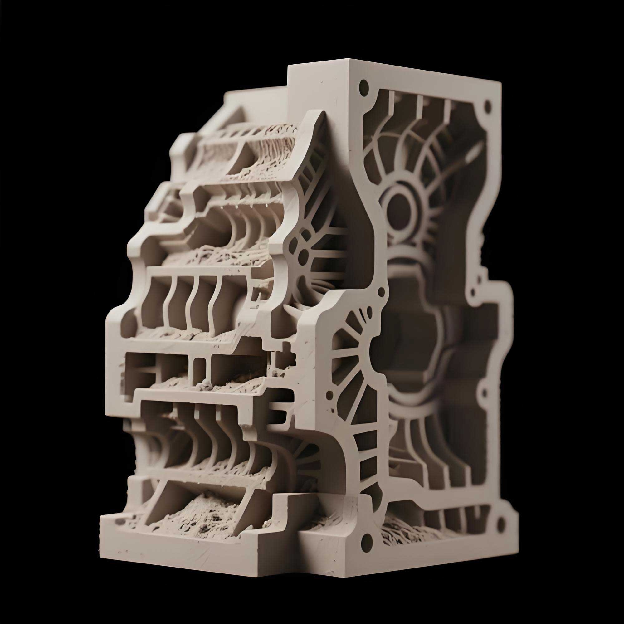
The sand mold for Plan B was designed with a “flat-printing, vertical-pouring” configuration, as illustrated in the schematic above. The outer sand molds represented the two cover plate side walls, and the middle core represented the blade channel. A central vent hole was opened at the core center, connected to the side walls, and a top vent was directly open to the atmosphere. By printing the entire blade core as one monolithic structure, I achieved an excellent dimensional accuracy of the flow channel, with tolerances within ±0.2 mm. After printing, the mold halves were sealed with sealing paste around the parting line and fixed with a dedicated clamping fixture to prevent any movement during pouring.
For the internal surface coating, I used a flow coating method to achieve a smooth surface finish. The flow channel is the most important functional surface of the impeller, so the coating thickness was carefully controlled. A Baume hydrometer and a comb-type wet film thickness gauge were used to maintain the coating thickness between 0.15 mm and 0.25 mm. A water-based composite coating was applied to reduce the risk of sand burning. After coating, the molds were dried in an oven at 100–130 °C for 2–3 hours. This process ensured that the final casting surface quality met the required specification.
Numerical Simulation of Mold Filling
Numerical simulation was an essential tool in comparing the two casting process plans. I used commercial casting simulation software to analyze the mold filling behavior, solidification, and defect risk. The governing equations for the mold filling process were based on the Navier-Stokes equations for incompressible viscous flow. For a Newtonian fluid with constant density, the continuity and momentum equations are given by:
$$ \nabla \cdot \mathbf{u} = 0 \tag{1} $$
$$ \rho \left( \frac{\partial \mathbf{u}}{\partial t} + (\mathbf{u} \cdot \nabla) \mathbf{u} \right) = -\nabla p + \mu \nabla^2 \mathbf{u} + \rho \mathbf{g} \tag{2} $$
where \(\mathbf{u}\) is the velocity vector, \(p\) is the pressure, \(\rho\) is the density of molten iron, \(\mu\) is the dynamic viscosity, and \(\mathbf{g}\) is the gravitational acceleration. The volume-of-fluid (VOF) method was employed to track the free surface of the molten metal. The heat transfer during filling and solidification was modeled using the energy equation:
$$ \rho c_p \left( \frac{\partial T}{\partial t} + \mathbf{u} \cdot \nabla T \right) = \nabla \cdot (k \nabla T) + Q \tag{3} $$
where \(T\) is the temperature, \(c_p\) is the specific heat, \(k\) is the thermal conductivity, and \(Q\) represents the latent heat release during solidification. The solidification model also accounted for the fraction of solid phase using the lever rule or Scheil equation.
Table 2 summarizes the initial conditions and material properties used in the simulation for HT250 gray iron.
| Parameter | Value |
|---|---|
| Liquidus temperature (°C) | 1180 |
| Solidus temperature (°C) | 1120 |
| Latent heat (kJ/kg) | 210 |
| Thermal conductivity (W/m·K) | 40 (at 20°C), 28 (at 1200°C) |
| Specific heat (J/kg·K) | 500 (solid), 800 (liquid) |
| Density (kg/m³) | 6850 (liquid), 7150 (solid) |
| Viscosity (Pa·s) | 0.005 |
| Pouring temperature (°C) | 1430 ± 10 |
| Mold initial temperature (°C) | 25 |
Table 2: Material properties and simulation parameters
The simulation results for Plan A predicted several high-risk areas for air entrapment. Figure 1 (shown earlier) illustrates the air pressure distribution at the final stage of filling. The pressure peaks corresponded to locations where gas could not escape easily, leading to potential blowholes. In contrast, Plan B showed a smooth progression of the liquid front, with no significant air pressure build-up. The vertical orientation allowed gas to rise upward and exit through the top vents. The simulation also indicated that the thin blades, with a minimum thickness of 2 mm, would be completely filled under the conditions of Plan B, while Plan A showed a high risk of cold shut. These findings convinced me to choose Plan B for actual production.
Production Verification and Results
For the production trial, I fabricated the molds for both plans using 3D sand printing. Plan A required a conventional sand core assembly, while Plan B used the monolithic printed core. The molds were coated and dried as described earlier. Before pouring, the molds were secured appropriately: Plan A used weight plates on top, and Plan B used a clamping fixture tightened on both sides. The pouring temperature was held at 1430 °C ± 10 °C, with a pouring time of approximately 8 seconds. This was achieved by controlling the gating system and the pouring cup size. The pouring time was estimated from the formula based on the filling rate and casting mass:
$$ t = \sqrt{2 \cdot \frac{G}{k \cdot A}} \tag{4} $$
where \(G\) is the pouring mass (including gating system) in kg, \(A\) is the effective cross-sectional area of the choke in cm², and \(k\) is a fluidity coefficient for gray iron, taken as 0.8. For our casting with a total metal mass of about 20 kg and a choke area of 2.8 cm², the calculated pouring time was about 7.8 seconds, which matched the actual pouring time well.
After solidification and cooling, the sand molds were shaken out. The casting from Plan A was found to have severe defects, including gas holes, core shift, and sand inclusion, making it unacceptable. The casting from Plan B, on the other hand, exhibited a clean surface without any visible sand burning, gas porosity, or misrun. Figure 2 shows the casting after shakeout and before cut-off of the gating system. The excellent surface quality of the Plan B casting confirmed the effectiveness of the vertical pouring orientation and the monolithic printed core.
After cutting off the risers and gating system, the casting was ground and blasted. The dimensional inspection showed that the casting met the CT9 tolerance grade. The flow channel surface roughness was measured with a surface roughness tester, yielding an average Ra of approximately 18–22 μm. This is quite good for as-cast gray iron surfaces and satisfied the customer’s acceptance criteria. Figure 3 displays the casting after grinding and blasting, with minor flash remaining.
Comparison of Plan A and Plan B
The production trial clearly demonstrated the advantages of Plan B over Plan A. A summary of the comparison is provided in Table 3.
| Aspect | Plan A (Horizontal) | Plan B (Vertical) |
|---|---|---|
| Core structure | Assembled from multiple cores | Monolithic 3D printed core |
| Gas evacuation | Poor – risk of air entrapment | Excellent – natural upward venting |
| Filling pattern | Turbulent, potential cold shuts | Stable, complete filling of thin blades |
| Casting defects | Porosity, core shift, sand inclusion | None observed |
| Dimensional accuracy | Lower – accumulated core errors | High – within ±0.2 mm |
| Surface roughness Ra (μm) | Not measurable due to defects | 18–22 |
| Process yield | Low | High |
Table 3: Comparison of the two casting process plans
From this comparison, I concluded that for narrow channel impellers, the vertical pouring layout combined with 3D sand printing is the most reliable and efficient method. The ability to print the entire blade core in one piece avoids the core assembly errors and weak joints that plague conventional manufacturing. Moreover, the vertical orientation naturally solves the gas evacuation problem because density differences drive gas upward through the risers. This greatly reduces the risk of porosity and misrun.
Cost and Time Efficiency
Another important benefit of 3D sand printing is the significant reduction in cost and lead time. In a conventional sand casting process, the development of this impeller would require a metal pattern and core boxes. For the two-casting production run, the pattern cost was estimated at about 20,000 RMB, with a pattern production cycle of 22 days. Additionally, molding, core making, and core assembly would require 3–5 days. In contrast, using 3D sand printing, the cost for sand molds and cores was only about 3,000 RMB, and the entire process from design to casting delivery took just 7 days. Table 4 shows a detailed cost and time comparison.
| Item | Conventional Sand Casting | 3D Sand Printing |
|---|---|---|
| Tooling cost (RMB) | 20,000 | 0 |
| Tooling production time (days) | 22 | 0 (direct printing) |
| Molding/core making time (days) | 3–5 | 1–2 (printing and assembly) |
| Total cost for 2 castings (RMB) | ~25,000 | ~3,500 |
| Total lead time (days) | 25–27 | 7 |
Table 4: Cost and lead time comparison
The cost advantage becomes even more pronounced for prototype and small-batch production. Since no tooling is required, design changes can be made quickly and inexpensively. This aligns perfectly with the modern trend of accelerated product development cycles. Engineers can now optimize the impeller geometry without worrying about tooling constraints, and manufacturers can respond to customer demands with greater flexibility and adaptability.
Improvements and Further Developments
Encouraged by the success of the first trial, I applied the same principles to several other narrow channel impeller models with different dimensions. All of these castings were produced using 3D sand printing and the vertical pouring process. The results were consistently good, with no casting defects and high dimensional accuracy. To further improve productivity, I redesigned the casting process to accommodate two impellers per mold (1 mold with 2 cavities). This modification increased the utilization of the 3D printing build volume and reduced the per-piece cost. The improved layout is shown in Figure 4. With this arrangement, the filling time was slightly adjusted to maintain a similar pouring rate per cavity.
In addition, I explored the effect of various sand grain sizes and binder contents on the surface quality of the printed cores. The 100/140 mesh silica sand produced a fine surface finish, which directly contributed to the low roughness of the cast flow channel. I also experimented with different coating formulations to further reduce the Ra value. Water-based zirconia coatings gave the best results, achieving Ra values below 15 μm in some trials. However, for the current application, the standard composite coating was sufficient.
Conclusions
Through this production practice, I have demonstrated the following key conclusions:
- The combination of 3d sand printing and a monolithic blade core significantly improves the casting quality and dimensional accuracy of narrow channel impellers. The flow channel dimensions can be controlled within ±0.2 mm, which is difficult to achieve with conventional core assembly.
- The vertical pouring process solves the core strength and gas evacuation problems that are common in thin-blade impellers. It allows reliable casting of blades with a minimum wall thickness of 2 mm and outlet widths of 4–8 mm, enabling excellent filling and sound microstructures.
- 3d sand printing drastically reduces the cost and lead time for prototype and small-batch production. The elimination of tooling costs, combined with faster mold fabrication, makes it an economically superior method for complex castings. In this project, the cost was reduced by more than 80% and the lead time by over 70% compared to conventional tooling.
- The flexibility of 3d sand printing facilitates rapid design iterations and process optimization. The ability to modify the gating system and core layout without producing new tooling is a game-changer for casting development.
In the future, I plan to further optimize the 3D printing parameters to enhance the mechanical strength of the sand molds, enabling larger and heavier castings. In addition, I will investigate the use of recycled sand in the 3D printing process to reduce material waste and environmental impact. The successful application described in this paper serves as a clear evidence that 3d sand printing is not only a prototyping technology but a reliable production method for high-quality complex castings.
To summarize, the production of narrow channel impellers using 3D printed sand molds and vertical pouring has proven to be robust, cost-effective, and technically superior. This approach opens new possibilities for the casting industry, especially for components with internal geometries that are impossible or uneconomical to produce by conventional means. As more manufacturers adopt this technology, I believe that 3d sand printing will become an indispensable tool in the foundry of the future.