
1. Introduction
In the context of global industrial upgrading, 3d printing sand casting has emerged as a transformative technology that reshapes the traditional foundry landscape. Also known as additive manufacturing, this process builds physical objects layer by layer from digital models, in stark contrast to conventional subtractive manufacturing. The unique value of 3d printing sand casting lies in its ability to produce complex geometries, customized components, and lightweight structures without the need for expensive tooling. As an engineer involved in the development and application of industrial 3D printing systems, I have witnessed how this technology is moving from the introductory phase into a period of rapid growth. Government policies, such as the action plan issued by multiple ministries in China in December 2017, have provided clear targets and requirements for the industry. Today, the 3D printing ecosystem is relatively complete, spanning raw materials, equipment, software, and downstream applications.
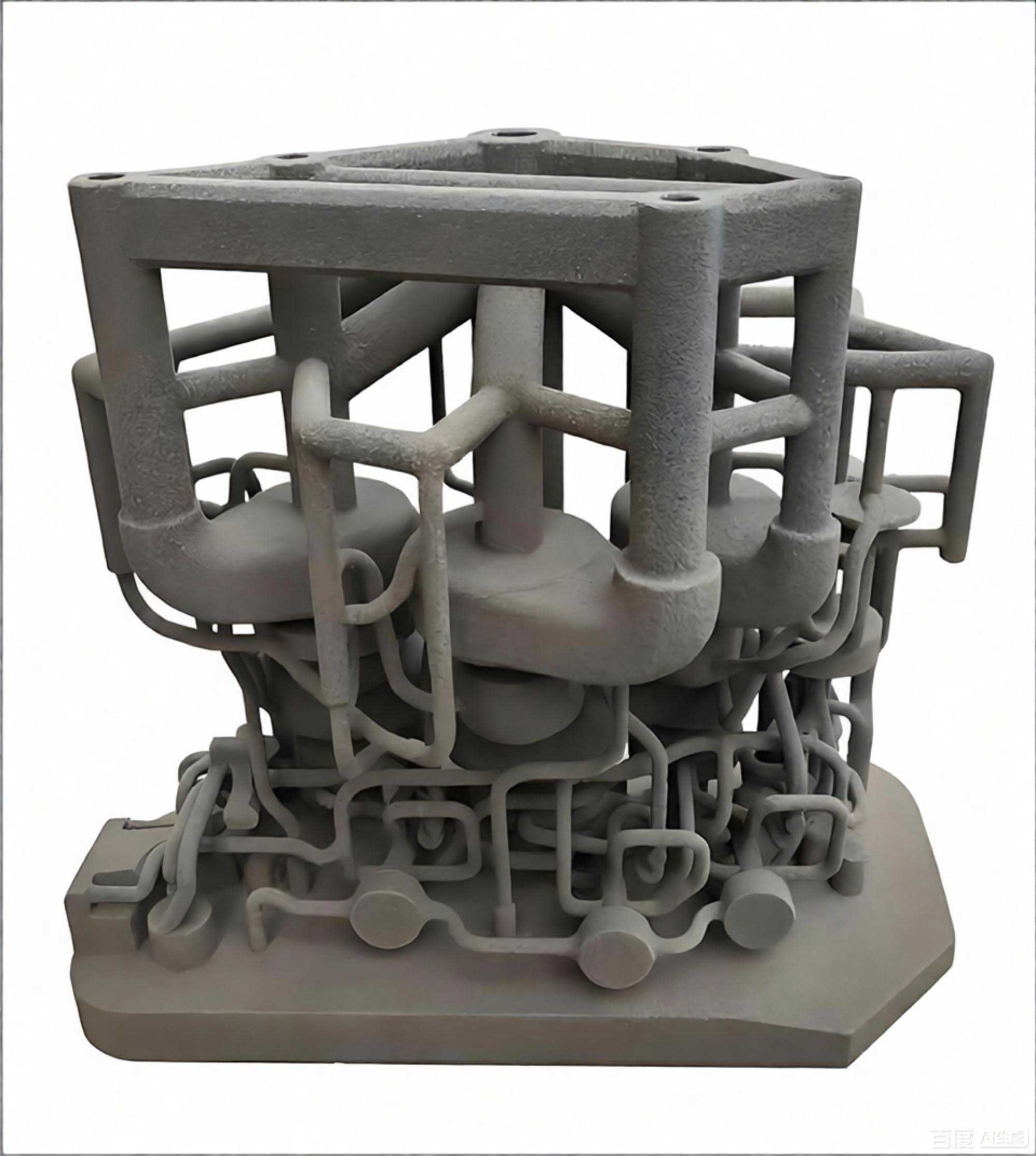
The term 3d printing sand casting specifically refers to the use of binder jetting to produce sand molds and cores for metal casting. In this process, a printhead selectively deposits a liquid binder onto a thin layer of sand, similar to how an inkjet printer works. The powder bed acts as the paper, and the binder acts as the ink. After each layer is printed, the build platform lowers by one layer thickness, a new layer of sand is spread, and the process repeats until the complete sand core or mold is formed. This method eliminates the need for traditional pattern making, core boxes, and many manual operations. It drastically shortens the production cycle and improves dimensional accuracy. For example, in a typical application, the production period can be shortened by 50%, and dimensional tolerances improve from ±1 mm to ±0.5 mm. Productivity increases three to five times, and the yield rate improves by 20% to 30%. These quantitative benefits make 3d printing sand casting an indispensable tool for modern foundries.
2. Fundamental Principles and Technical Description
The core of 3d printing sand casting relies on the Three-Dimensional Printing (3DP) technology. The process can be described step by step as follows:
- The digital model of the sand core or mold is sliced into a series of 2D cross-sectional images.
- The build platform is lowered by one layer thickness, typically between 0.2 mm and 0.5 mm.
- A recoater spreads a uniform layer of sand, such as silica sand or cerabeads, over the build area.
- The printhead moves across the bed and selectively deposits binder droplets onto the sand according to the slice image.
- The binder reacts with the sand and hardens, bonding the particles together.
- Steps 2 through 5 are repeated until the entire component is formed.
- The unbound sand is removed, revealing the finished sand core or mold.
One key advantage of this process is the absence of thermal stress, which allows the fabrication of large and intricate sand structures without warping or cracking. The layer-by-layer approach enables the creation of undercuts, internal channels, and complex cooling passages that are difficult or impossible to achieve with traditional core-making methods. For a typical casting sand core, the total build time can be modeled as:
$$T_{\text{total}} = N_{\text{layer}} \left( t_{\text{coating}} + t_{\text{printing}} \right)$$
where \(N_{\text{layer}} = \frac{H}{h}\) is the number of layers, \(H\) is the total height of the printed object, \(h\) is the layer thickness, \(t_{\text{coating}}\) is the time required for spreading one layer of sand, and \(t_{\text{printing}}\) is the time to print one layer. In practice, \(t_{\text{printing}}\) depends on the number of printheads, the number of nozzles, the binder drop frequency, and the scanning speed. For a single printhead with width \(W_{\text{head}}\) and scanning speed \(v\), the printing time for one layer can be approximated by:
$$t_{\text{printing}} = \frac{A_{\text{layer}}}{W_{\text{head}} \cdot v} \cdot \frac{1}{n_{\text{passes}}}$$
where \(A_{\text{layer}}\) is the area of the layer, and \(n_{\text{passes}}\) is the number of simultaneous passes if multiple heads are used. Increasing the number of printheads or the scanning speed directly reduces \(t_{\text{printing}}\), thereby increasing the overall throughput. This mathematical framework is essential when analyzing efficiency improvements in 3d printing sand casting.
Furthermore, the binder saturation level plays a critical role in determining the strength and surface finish of the printed sand mold. The binder-to-sand ratio \(R_{\text{binder}}\) can be defined as:
$$R_{\text{binder}} = \frac{V_{\text{binder}}}{V_{\text{sand}}} \times 100\%$$
Typical values range from 2% to 8% depending on the sand type and the required strength. A higher ratio improves strength but increases cost and may reduce permeability, which is undesirable for casting applications. Thus, optimizing the binder amount is a key consideration in 3d printing sand casting.
3. Advantages over Traditional Casting
The transition from traditional sand casting to 3d printing sand casting offers numerous advantages that fundamentally change the way foundries operate. Traditionally, producing a sand mold requires multiple steps: pattern fabrication, core making, molding, core assembly, and closing. Each step involves significant manual labor, lead time, and tooling costs. For complex components, these tasks become extremely challenging. In contrast, 3d printing sand casting directly prints the sand mold or core, bypassing pattern making and core box manufacturing. This simplifies the entire supply chain.
| Parameter | Traditional Sand Casting | 3D Printing Sand Casting |
|---|---|---|
| Tooling required | Yes (patterns, core boxes) | No tooling |
| Dimensional accuracy | ±1 mm | ±0.3 mm or better |
| Production cycle | Long (weeks) | Short (days) |
| Design flexibility | Limited by tooling | Virtually unlimited |
| Labor intensity | High | Low |
| Environmental impact | Dust, resin emissions, waste | Clean, no pattern waste |
| Batch size | Economical for large batches | Economical for small to medium batches |
From my experience, one of the most remarkable achievements of 3d printing sand casting is the realization of a “five-zero” foundry: zero crane requirements, zero patterns, zero heavy manual labor, zero waste sand and dust emissions, and zero temperature gradients (due to air conditioning). This concept has transformed the dirty, hot, and labor-intensive workshop into a clean, climate-controlled factory. The following table summarizes the performance improvements commonly observed after adopting 3d printing sand casting:
| Metric | Improvement |
|---|---|
| Production cycle reduction | Up to 50% |
| Dimensional accuracy | From ±1 mm to ±0.5 mm (or ±0.3 mm for high-precision) |
| Productivity increase | 3 to 5 times |
| Yield rate improvement | 20% to 30% |
| Labor cost reduction | Substantial |
These improvements are not marginal; they represent a paradigm shift in the foundry sector. The ability to print extremely complex internal channels and cooling circuits directly into the sand core enables the production of castings with superior mechanical properties and reduced weight, which is particularly valuable in aerospace and automotive industries.
4. Industry Chain of 3D Printing Sand Casting
The 3d printing sand casting industry has evolved into a complete value chain over nearly four decades. This chain can be divided into three main segments: upstream, midstream, and downstream. A comprehensive understanding of this chain is crucial for identifying bottlenecks and opportunities.
4.1 Upstream: Materials and Components
The upstream sector includes raw materials such as sand (silica sand, cerabeads, chromite sand), binders (furan resin, phenolic resin), and additives. The performance of these materials directly influences the quality of the final sand mold. For instance, the particle size distribution and shape affect the surface finish and permeability. The binder type and catalyst system determine the curing speed and strength. Additionally, upstream components include printheads, motion systems, control electronics, and software. High-end components like industrial printheads are still primarily imported, which increases procurement cost and lead time. However, domestic alternatives are gradually emerging, reducing dependency and improving supply chain resilience. The following table presents the upstream categories and their typical suppliers:
| Category | Examples | Domestic / Imported |
|---|---|---|
| Silica sand | Fine round sand, sub-angular sand | Domestic |
| Ceramic sand | Cerabeads | Imported/Domestic |
| Binder | Furan resin, phenolic resin | Domestic/Imported |
| Printhead | Piezo inkjet heads | Mostly imported |
| Motion system | Servo motors, linear guides | Imported/Domestic |
| Software | SLICER, process control | Domestic/Imported |
Because the quality of the upstream components affects the reliability and precision of 3d printing sand casting equipment, several foundry groups have integrated backward to develop their own printheads and control software. This vertical integration is a strategic move to secure the supply chain and reduce costs. In fact, some Chinese manufacturers have successfully produced commercial machines using self-developed printhead modules, which marks a major milestone.
4.2 Midstream: Equipment Manufacturers
The midstream segment consists of companies that design and manufacture 3D printers for sand molds. These machines range from small desktop-sized units to massive industrial systems with build volumes exceeding 2200 mm in one dimension. Industrial-grade equipment accounts for the largest share of the market revenue, approximately 40% of the total 3D printing industry output in China. Several domestic manufacturers have emerged, offering a variety of models with different build sizes, numbers of printheads, and automation levels. For example, a leading manufacturer provides both dual-box and single-box configurations, as well as multiple options for printhead arrays. The following table lists representative industrial sand printer models (names and exact specifications are generic for illustrative purposes):
| Model | Build Envelope (mm) | Box Type | Layer Thickness (mm) | Throughput (L/h) |
|---|---|---|---|---|
| Model A | 2500 × 1250 × 700 | Dual | 0.3 | 15 |
| Model B | 2200 × 1200 × 700 | Dual | 0.3 | 14 |
| Model C | 2500 × 1250 × 800 | Single | 0.4 | 12 |
| Model D. | 1800 × 1000 × 800 | Single | 0.3 | 9 |
| Model E | 800 × 500 × 500 | Single | 0.2 | 3 |
These devices typically feature a powder spreader, a printhead carriage, a build platform, a binder supply system, and a cleaning/recycling system. The trend in equipment development is toward modular design, which allows users to scale up from single machines to fully automated production cells. In modern digital foundries, multiple printers are integrated with robotic handling, automated sand cleaning stations, and high-bay warehouses, creating a seamless flow from digital model to finished sand core.
4.3 Downstream: Applications and Services
The downstream sector covers all applications that utilize 3d printing sand casting services. These applications range from aerospace components and automotive engine parts to machinery and medical devices. The main value propositions are rapid prototyping, low-volume production, and complex geometry realization. For prototyping, 3d printing sand casting reduces the time to obtain castings from months to days, enabling faster design iterations. For production, it offers an economical solution for small batches because no tooling cost is incurred. The table below shows the distribution of downstream applications in terms of sales share:
| Industry | Approx. Share (%) | Typical Examples |
|---|---|---|
| Mechanical manufacturing | 20 | Pump impellers, valve bodies, hydraulic manifolds |
| Consumer electronics | 15 | Light-alloy frames, heat sinks |
| Automotive | 20 | Cylinder heads, turbine housings, brake components |
| Aerospace | 15 | Brackets, casings, combustion chambers |
| Medical | 10 | Surgical instruments, implants |
| Others | 20 | Art, architecture, education |
In particular, the integration of 3d printing sand casting with traditional casting processes accelerates the development and production of key parts in diesel engines and aircraft engines. The printed sand cores allow for optimized internal cooling passages that enhance engine efficiency. Another important application is the combination of 3D printed sand molds with traditional mold-making techniques to produce injection molds or die-casting dies with conformal cooling channels. This hybrid approach significantly improves cooling efficiency, reduces product defects, shortens manufacturing cycles, and lowers costs.
5. Efficiency Improvement in Sand 3D Printers
Despite the many advantages, one of the main challenges facing the adoption of 3d printing sand casting in large-scale production is the relatively low working efficiency of current sand printers. The build rate, defined as the volume of printed sand per unit time, is typically limited by the binder jetting speed, the powder spreading time, and the number of printheads. To increase the throughput, several strategies can be employed. In this section, I will share my technical insights into improving the efficiency of sand 3D printers.
5.1 Printhead Selection and Configuration
Choosing the right printhead is the most direct way to enhance printing speed. Printheads with higher native resolution or a larger number of nozzles can deposit more binder per pass. The theoretical printing speed is proportional to the total number of active nozzles and the firing frequency. For a given layer area, we can express the maximum printing throughput as:
$$V_{\text{max}} = \frac{N_{\text{nozzles}} \cdot f_{\text{drop}} \cdot V_{\text{drop}}}{R_{\text{binder}}} \times h$$
where \(N_{\text{nozzles}}\) is the total number of nozzles, \(f_{\text{drop}}\) is the droplet ejection frequency, \(V_{\text{drop}}\) is the volume of a single droplet, \(R_{\text{binder}}\) is the binder saturation ratio, and \(h\) is the layer thickness. To increase \(V_{\text{max}}\), one can increase \(N_{\text{nozzles}}\) by using multiple printheads arranged in a staggered array. Doubling the number of printheads can nearly double the printing speed, provided that the motion system can handle the additional mass and the binder supply can deliver sufficient flow. However, there is a practical limit because the printhead array requires more frequent maintenance and cleaning. In many industrial designs, a set of two to six printheads is used, balancing cost and performance.
5.2 Optimization of Moving Components
The motion system of a sand printer typically consists of a gantry that moves the printhead assembly across the build area. The scanning speed and acceleration directly affect the layer printing time. Lighter materials such as carbon-fiber-reinforced composites or aluminum alloys can reduce inertia, allowing higher accelerations without losing precision. The desired acceleration \(a\) and maximum speed \(v_{\text{max}}\) determine the time required for one scan across the build bed. Assuming a constant acceleration and deceleration profile, the time for a single scan of distance \(L\) can be approximated by:
$$t_{\text{scan}} = \frac{L}{v_{\text{max}}} + \frac{v_{\text{max}}}{a}$$
where \(a\) is the acceleration. If the printhead array covers a width \(W_{\text{array}}\), the number of scans needed for a layer is \(N_{\text{scans}} = \frac{W_{\text{layer}}}{W_{\text{array}}}\). The total printing time per layer is then \(t_{\text{printing}} = N_{\text{scans}} \cdot t_{\text{scan}}\) (neglecting the turning time). By increasing the acceleration \(a\) and the scan speed \(v_{\text{max}}\), the printing time decreases. However, too high acceleration can cause droplet placement errors due to gantry vibration. Therefore, optimization of the frame stiffness and vibration damping is critical.
5.3 Compact Printing Cycle
Another approach is to reduce the non-printing time within each cycle, such as the time for lowering the platform, spreading sand, and returning the recoater to home. These actions can be overlapped with printing operations in sophisticated machine designs. For example, in a dual-box system, while one build box is printing, the other can be unpacked and cleaned. This parallel operation significantly increases the overall efficiency of the whole production line. The cycle time per box can be expressed as:
$$T_{\text{cycle}} = T_{\text{print}} + T_{\text{setup}}$$
where \(T_{\text{setup}}\) includes sand filling, box indexing, and post-processing. By having two boxes, the effective setup time per part is reduced to almost zero if the setup of the second box occurs during the printing of the first. The equation becomes \(T_{\text{cycle, parallel}} = \max(T_{\text{print,1}}, T_{\text{setup,2}})\), which effectively hides setup delays. This is one of the most effective ways to increase the productivity of 3d printing sand casting cells.
5.4 Layer Thickness Optimization
Increasing the layer thickness \(h\) reduces the number of layers, thus reducing the total printing and coating time. However, a thicker layer can compromise the surface finish and dimensional accuracy, especially for fine details. The relationship between layer thickness and resolution is well known. For sand casting molds, the acceptable surface roughness is often lower than that of machining, but a thicker layer may produce a stair-stepping effect. The maximum allowable layer thickness depends on the binder penetration depth and the sand particle size. Typically, a layer thickness of 0.3 to 0.4 mm is used. A careful cost-benefit analysis can help select the appropriate layer thickness for a given part. The time saving is expressed by:
$$\Delta T = T \left(1 – \frac{h_1}{h_2}\right)$$
where \(h_1\) and \(h_2\) are the original and increased layer thicknesses, respectively. If productivity is the priority and the part has no tight tolerance, increasing the layer from 0.3 mm to 0.4 mm can reduce the build time by 25%.
5.5 Binder Delivery and Jetting Reliability
Efficient binder delivery ensures that the printheads can operate continuously without downtime due to clogging or supply fluctuations. A well-designed binder recirculation system with degassing and filtration prevents nozzle failure. The reliability of jetting is measured by the mean time between clogs (MTBC). Longer MTBC improves the effective utilization of the printer. The overall equipment effectiveness (OEE) can be calculated as:
$$\text{OEE} = \frac{T_{\text{available}} – T_{\text{downtime}}}{T_{\text{available}}} \times 100\%$$
where \(T_{\text{available}}\) is the planned production time and \(T_{\text{downtime}}\) includes all stoppages. In continuous operation, high OEE values (above 85%) are required for a cost-effective production line. Weekly cleaning and preventive maintenance schedules play a crucial role in maintaining OEE.
6. Case Studies and Practical Applications
The real-world impact of 3d printing sand casting can be observed in several digital intelligent factories that have been built in China. These factories integrate multiple sand 3D printers with central sand blasting systems, gantry robotics, and automated storage. The entire process from digital model to finished sand core is digitalized, reducing lead times by more than half. In one typical application, a diesel engine cylinder head with complex internal cooling channels was produced with a wall thickness of only 4 mm and a dimension tolerance of ±0.3 mm. The traditional method would have required a complex core assembly of 15 separate cores, taking several weeks. With 3d printing sand casting, the entire core was printed as one piece in 48 hours, eliminating assembly errors and reducing the delivery time by 40%.
Another compelling case is the manufacture of a titanium alloy impeller for aerospace applications. The investment casting process was used, where a 3D printed sand mold was used to create a wax pattern? Actually, more commonly, the sand mold itself is used for aluminum or iron castings. For aerospace, a printed sand mold can be directly used for titanium castings due to its high refractory capability. The design freedom allowed the engineer to integrate a conformal cooling channel around the crystallizer, resulting in a faster solidification and a 20% improvement in mechanical properties. The cost of the mold was reduced by 70% because no machine tooling was needed. These examples illustrate why 3d printing sand casting is considered a disruptive innovation.
Moreover, the combination of 3D printing with traditional mold-making is used to improve injection molds. A printed sand insert can be used as a prototype mold cavity for small batch production of plastic parts, with lead times shortened from six weeks to one week. The table below compares the traditional and hybrid approaches:
| Criteria | Traditional Mold | 3DP Mold Insert |
|---|---|---|
| Lead time to first part | 6-8 weeks | 1-2 weeks |
| Tooling cost | $20,000 – $100,000 | $2,000 – $10,000 |
| Cooling channels | Straight drilled | Conformal |
| Cycle time | Baseline | -30% |
| Maintenance | Complex | Simple |
Such examples demonstrate the versatility and economic viability of 3d printing sand casting beyond merely producing molds for metal casting.
7. Future Trends and Outlook
Based on my observations and analysis, the future of 3d printing sand casting will evolve along several important directions. First, equipment diversification will continue. Different application scenarios require different machine capabilities. We will see more compact desktop sand printers for research and education, as well as ultra-large printers for producing entire engine blocks. Second, the localization of key components will accelerate. Import substitution of printheads, servo control systems, and industrial software will reduce expenditures and shorten delivery times. I have already seen successful cases where domestic printhead modules replace imported ones, resulting in 40% lower equipment costs. Third, the demand for industrialization is robust. As more foundries pursue green and intelligent manufacturing, the adoption of 3d printing sand casting will become mainstream rather than exceptional. The construction of digitalized factories with multiple 3D printers is increasing across various regions.
Fourth, cost reduction and efficiency enhancement are continuous goals. The total cost of ownership (TCO) for a sand 3D printer can be modeled as:
$$\text{TCO} = C_{\text{equipment}} + C_{\text{maintenance}} + C_{\text{material}} + C_{\text{energy}}$$
where \(C_{\text{equipment}}\) is the purchase price amortized over the useful life, \(C_{\text{maintenance}}\) includes spare parts and service, \(C_{\text{material}}\) is the cost of sand, binder, and any additives, and \(C_{\text{energy}}\) is the electricity and compressed air consumption. Through optimized machine design and material recycling, both capital expenditures and operating expenses can be reduced. For example, closed-loop sand recycling systems can reclaim more than 95% of unbound sand, significantly lowering material waste. Meanwhile, improvements in printhead life can reduce the consumables cost per printed part.
Fifth, the establishment of systematic standards is crucial. The 3d printing sand casting industry is still young, and there is a lack of unified standards for raw materials, process parameters, and equipment qualification. Standards will help ensure consistent quality, promote interoperability between different manufacturers, and facilitate the certification of printed molds for safety-critical applications. The following table lists the standard landscape that is likely to be developed:
| Standard Category | Examples | Status |
|---|---|---|
| Material | Sand particle size distribution, binder viscosity, storage stability | In development |
| Process | Layer thickness, printing speed, binder saturation | In development |
| Equipment | Build volume accuracy, repeatability, safety requirements | Draft |
| Application | Acceptance criteria for sand cores/molds, testing methods | Draft |
| Service | Data formats, workflow, contract conditions | Emerging |
In addition to these technical trends, the business model is shifting from selling machines to providing integrated solutions, including software, materials, service, and even castings. This “pay-per-part” approach lowers the entry barrier for small foundries. Moreover, cloud-based platforms enable online quoting and remote monitoring, connecting customers with service providers seamlessly. All these factors will accelerate the adoption of 3d printing sand casting and solidify its position in the foundry industry.
8. Conclusion
In summary, 3d printing sand casting represents a fundamental change in how we manufacture metal components. It empowers foundries to produce intricate parts with high precision, short lead times, and reduced environmental impact. The technology has matured to a point where industrial machines are reliable and cost-effective for many production scenarios. The complete value chain—from raw materials to equipment and downstream applications—is evolving rapidly. As an engineer, I believe that the continued development of printhead technology, motion systems, and process control will further improve the efficiency and economics of 3d printing sand casting. The integration of robotics and artificial intelligence will lead to fully autonomous digital foundries, where the shop floor is clean, safe, and efficient. With the support of national policies and the collective effort of the industry, 3d printing sand casting is destined to play a vital role in the future of manufacturing.
Through the analysis presented in this article, I have tried to provide a comprehensive overview of the technology, its applications, and the promising strategies for enhancing productivity. The journey from a novel prototyping tool to a globally adopted production method is still ongoing, but the trajectory is clear. Embracing 3d printing sand casting is not just an option; it is a necessity for foundries that wish to remain competitive in the era of Industry 4.0. I am eager to see the next wave of innovations, from high-speed binder jetting systems to multi-material printing, which will unlock even greater possibilities. The future of casting is digital, and 3d printing sand casting is leading the way.