
In the early stages of developing a new casting, the required number of prototypes is usually small. Conventional foundry practice demands the fabrication of metal tooling, which is expensive and often takes one and a half to three months to complete. If a customer modifies the drawing during product development, the casting process may need to be revised, and sometimes even the die has to be changed. When the die modification is difficult or impossible, the die may be scrapped, resulting in major financial losses. Moreover, the entire cycle from process design to a finished metal mould is too long to respond quickly to customer requirements. Traditional casting also struggles with complex geometries that cannot be withdrawn from the mould. In those cases, many cores or loose pieces are required to form the shape, and several core boxes must be made to assemble the core package. This makes the casting procedure complicated and dimensional accuracy low. Three-dimensional (3D) printing technology can overcome these obstacles by enabling core and mould manufacture without a pattern, thus achieving rapid prototyping and small-series production.
As an emerging technology, 3D printing has become a powerful tool in the foundry industry. Because 3D printing is almost unrestricted by spatial geometry, it can produce extremely complex components. In the work described here, I used 3D printing sand casting as the core method to combine digital simulation with direct sand-mould manufacture. This approach enabled the rapid development of a multi-curved-surface impeller body casting that would otherwise require a complex core assembly and high-cost tooling.
1. Casting Structure Analysis
The impeller body is a typical complex casting. The customer specified the material as QT500-7 (spheroidal graphite cast iron). The maximum outer dimension is Φ660 mm × 202 mm, the casting mass is 105 kg, and the blade thickness is 21 mm. There is a large hot spot at the centre of the casting. Six blades are twisted curved surfaces. With a conventional core-assembly method, each blade needs at least two cores to form the undercut surfaces, so the whole casting requires at least 12 separate cores. After assembling all those cores and pouring, gaps between cores produce extensive flash or fins. Grinding those fins is difficult, and excessive grinding can easily create non-smooth transitions on the curved blade surfaces, thereby impairing the hydraulic performance of the impeller. In addition, because the wall thickness varies greatly, the internal region is prone to shrinkage porosity and other shrinkage defects. Therefore, a rapid pouring system with effective feeding of the thick sections is necessary. Table 1 summarizes the casting parameters.
| Parameter | Value |
|---|---|
| Material | QT500-7 |
| Maximum outer diameter (mm) | 660 |
| Overall height (mm) | 202 |
| Mass (kg) | 105 |
| Blade thickness (mm) | 21 |
| Number of blades | 6 |
| Blade geometry | Twisted curved surfaces |
| Central hub thickness (mm) | 180 |
2. Casting Process Design
2.1 Considerations for Feeding and Pouring
Because the impeller body is made of ductile iron, it exhibits an expansion phase during solidification. However, the thick central hub (180 mm) is a strong heat centre and requires adequate feeding. Rapid pouring is also essential to avoid cold shuts and to promote a favourable temperature gradient. I evaluated two different feeding strategies using casting simulation software.
2.2 Alternative 1: A Single Top Riser
The first design used one large top riser placed directly above the central hub. The intention was to feed the entire central hot spot and the blades through the riser neck. Simulation results showed that the riser had to be extremely large, and the riser neck diameter had to be almost as large as the central cylinder diameter in order to draw all shrinkage into the riser. Such a massive riser creates an artificial hot spot at the top of the hub, causing local overheating, coarse microstructure in the riser contact area, and severe difficulties in riser removal. The figure below illustrates the revised design, which proved more efficient.
The modulus of the casting can be expressed by
$$M = \frac{V}{A}$$
where \(V\) is the volume of the feeding zone and \(A\) is the cooling surface area. For a safe feeding condition, the riser modulus \(M_r\) must satisfy
$$M_r = f M$$
with a safety factor \(f\) typically between 1.2 and 1.5. In the single-riser design, the required \(M_r\) was so large that the riser became impractical for both soundness and economy.
2.3 Alternative 2: Two Top Risers with a Chill
To overcome these disadvantages, I designed two smaller top risers instead of one giant riser. The two risers are positioned not at the exact centre of the cylinder; they are offset slightly, so they feed the hot spot while reducing the artificial thermal centre. This arrangement also makes subsequent riser removal easier. A steel chill was placed under the bottom of the central hub to accelerate cooling from the bottom upward, establishing a favourable directional solidification. The gating system was designed through these two risers: a ceramic foam filter was placed on top of each riser to filter the melt and to reduce turbulence. Since pouring through one filter continuously may erode it, I poured alternately through the two risers – first into one riser for a period, then shifted to the other one. This practice protects the filters and also helps to distribute the superheat more evenly. Table 2 compares the two design alternatives.
| Item | Single top riser | Two top risers + chill |
|---|---|---|
| Number of risers | 1 | 2 |
| Riser neck diameter | Almost equal to hub diameter | Smaller, offset from centre |
| Artificial hot spot | Severe | Moderate, minimized |
| Feeding efficiency | Low, large volume required | High due to chill |
| Riser removal | Difficult | Easy |
2.4 Simulation of Solidification
I performed transient thermal simulation using a commercial casting simulation package. The solidification result for the selected design is presented conceptually in the simulation curve. The simulation confirmed that shrinkage porosity and shrinkage cavities are displaced into the risers. Although some porosity appears near the riser neck, in practice this region is directly connected to the riser and the riser remains superheated because the melt is poured through it. Therefore, the porosity can be pulled into the riser entirely during solidification. The solidification time follows Chvorinov’s rule:
$$t_s = B \left( \frac{V}{A} \right)^2$$
where \(B\) is a constant depending on the mould material and casting alloy. By comparing the local solidification time of the hub and the risers, I verified that the risers solidify last, ensuring a proper feeding path.
To quantify the pouring speed, I used the following empirical formula for ductile iron:
$$t_{\text{pour}} = K \sqrt{\delta W}$$
where \(W\) is the casting mass (kg), \(\delta\) is the average wall thickness (mm), and \(K\) is a coefficient depending on pouring temperature and mould conditions. For this impeller body, \(W = 105\) kg and \(\delta = 21\) mm. The computed pouring time was about 18 seconds, which meets the rapid pouring requirement.
3. Sand Mold Design and 3D Printing
3.1 Mold Splitting and Core Elimination
The sand mould was designed according to the selected gating and feeding scheme. The parting line was placed at the midplane of the blades, leaving a sand thickness of 40–50 mm around the cavity. Only two sand cores (the upper and lower halves) are needed to form the entire complex blade geometry. This dramatic reduction from 12 cores to 2 sand blocks is the key advantage of using 3D printing sand casting: shapes that cannot be withdrawn from a pattern are printed directly into the sand block, eliminating the need for numerous loose pieces and core boxes. Fewer sand blocks mean less assembly error, less flash, and higher dimensional consistency.
3.2 Shrinkage Allowance and Coating Thickness
The casting shrinkage allowance for this spheroidal graphite iron was set to 0.8%. The relationship between pattern dimension and casting dimension is
$$\delta_{\text{shrink}} = \frac{L_{\text{mold}} – L_{\text{casting}}}{L_{\text{casting}}} \times 100\%$$
where \(L_{\text{mold}}\) is the sand-mould cavity dimension and \(L_{\text{casting}}\) is the desired casting dimension. A pre-coating thickness of 0.2 mm was reserved on the cavity surfaces. Therefore, the CAD model of the 3D-printed sand mould was generated by applying a scale factor of 1.008 to the nominal casting dimensions and then offsetting the surface by 0.2 mm outward to account for the refractory coating.
3.3 Locating and Venting Features
To ensure accurate alignment of the upper and lower sand blocks, three conical sand-pin locating features were designed at the parting line. These sand pins and sockets are printed as an integral part of the mould. In addition, several handling recesses were provided on the external sides to facilitate lifting and closing of the heavy sand blocks. Venting holes were drilled or printed in the parting plane without communicating with the cavity, allowing gas from the burning sand to escape. The venting area is a critical factor for avoiding blowholes; the total vent cross-section should be at least 1.5% of the runner cross-section. The design considered a safe venting area and multiple positions.
3.4 3D Printing Specifications
The finalized mould data were sent to an external 3D printing service provider. The sand cores were printed layer by layer using a furan resin binder and silica sand. The dimensional tolerance of the printed sand cores was required to be CT7–CT8 according to ISO 8062. The sand core strength was specified as a cold tensile strength of at least 1.5 MPa. The 3D printing layer thickness was 0.3 mm, which gives a suitable surface finish for the mould cavity. The printed sand mould retains sufficient permeability and collapsibility, which are advantageous for casting quality and shakeout. The figure below shows a representative 3D-printed sand mould used in this application.
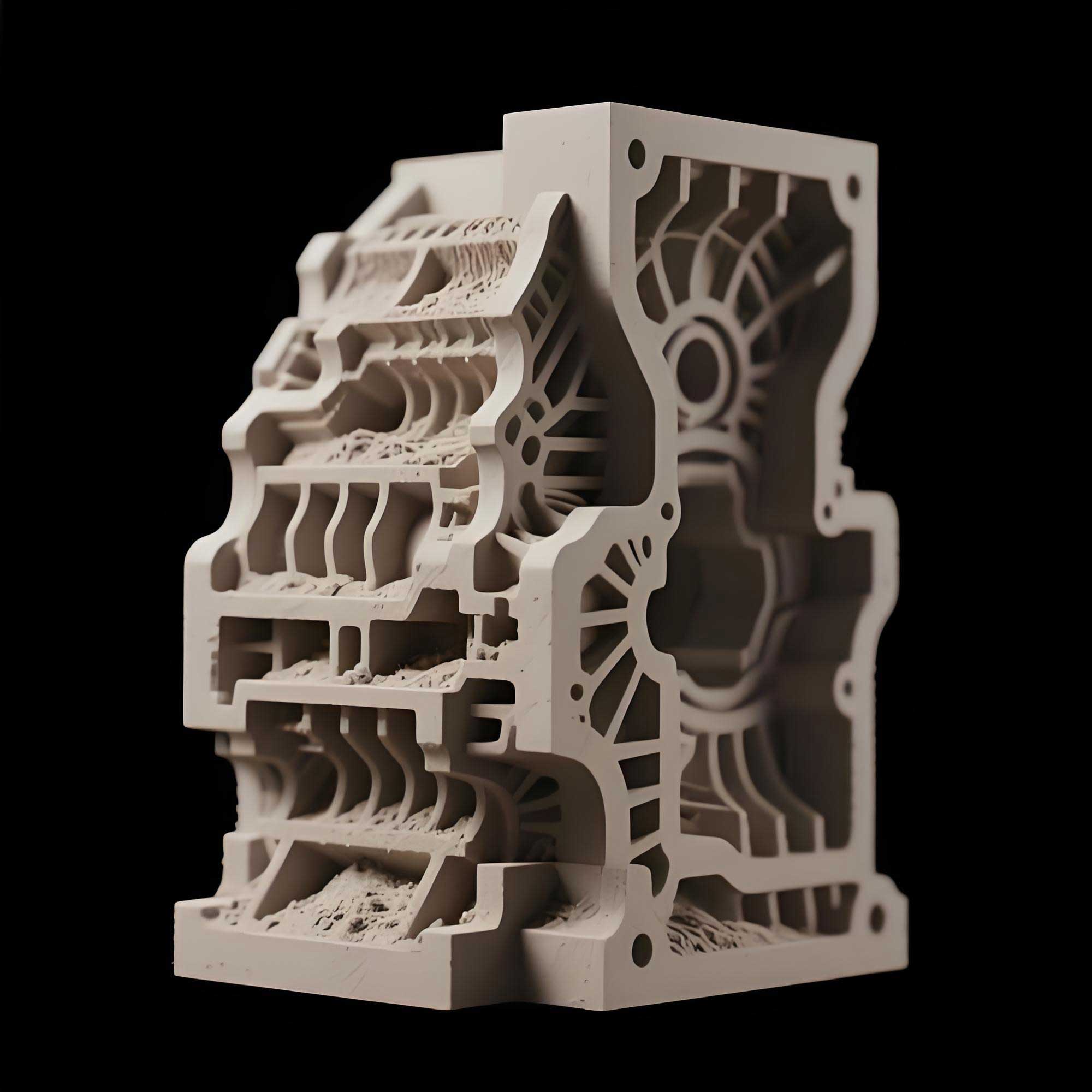
Table 3 lists the specifications of the 3D-printed sand mould used for the impeller body.
| Property | Value / requirement |
|---|---|
| Moulding material | Silica sand + furan resin |
| Printing layer thickness (mm) | 0.3 |
| Dimensional tolerance grade | CT7 – CT8 |
| Cold tensile strength (MPa) | ≥ 1.5 |
| Surface finish on cavity | Good enough for coating |
| Number of sand blocks per mould | 2 |
| Mould mass (kg) | ~126 |
| Parting line location | Midplane of blades |
| Shrinkage allowance (%) | 0.8 |
| Coating allowance (mm) | 0.2 |
3.5 Coating and Assembly
After the sand mould was delivered, I applied an alcohol-based refractory coating to all cavity surfaces. The coating thickness was controlled in the range of 0.15–0.20 mm using spray and brush passes. After coating, the mould was ignited with a torch to dry the coating and to burn off any residual volatile material. The cold metal chills, made of 45 steel, were also brush-coated with the alcohol-based coating and flame-heated before being placed in the cavity. The chill dimensions were designed so that their modulus is sufficiently high to accelerate solidification of the bottom hub region without creating a sharp thermal discontinuity that could cause stress. The mould closing process was performed carefully using the three conical locating pins. Since the total mould mass was about 126 kg, the mould was placed in a flask and the surrounding sand was compacted after closing, in order to prevent run-out during pouring.
4. Pouring and Quality Verification
4.1 Pouring Parameters
The impeller body was poured with nodular iron treated and inoculated by the sandwich method. The pouring temperature was controlled between 1360 °C and 1400 °C. Two ladles were used: the first poured the initial portion into the primary riser, and the second later shifted to the other riser as the mould filled. This procedure minimized the risk of filter clogging and distributed the metal temperature uniformly. The pouring time was measured at around 18–20 seconds, which agreed well with the calculated value. Table 4 summarizes the actual pouring process data.
| Parameter | Value |
|---|---|
| Pouring temperature (°C) | 1360 – 1400 |
| Mould material | 3D-printed furan sand |
| Pouring time (s) | 18 – 20 |
| Mould mass (kg) | 126 |
| Melt mass per casting (kg) | ~105 |
| Chill material | 45 steel |
| Filter type | Foamed ceramic, placed in risers |
| Cooling time after pouring | 2 hours |
4.2 Post-Casting Operations
After the casting had cooled to ambient temperature, the mould was shaken out. The castings were cleaned by shot blasting. Risers were removed with a band saw, and the remaining stubs were ground smoothly. The central hub and the blade surfaces were polished carefully, but because the 3D-printed mould produced a nearly fin-free surface, very little grinding was required. The surface finish was visibly superior to what is usually obtained from a 12-core assembly. The absence of parting lines across the blade profiles ensured smooth transitions, which is critical for hydraulic efficiency.
4.3 Inspection and Validation
All three impeller bodies produced were dimensionally inspected. The dimensions met the customer’s requirements. The castings also passed the ultrasonic inspection with no indications of major internal shrinkage or gas porosity. After machining, the samples were assembled and tested by the customer. The finished parts worked perfectly, and the customer expressed satisfaction. The key quality results are summarized in Table 5.
| Inspection item | Result |
|---|---|
| Dimensional inspection | Pass / conform to drawing |
| Surface roughness | Good, almost no flash |
| Ultrasonic inspection | No critical discontinuities |
| Radiographic inspection (selected areas) | No significant shrinkage porosity |
| Mechanical testing | Tensile strength ≥ 500 MPa (typical), elongation ≥ 7% |
| Hardness (HBW) | 170 – 230 |
| Machining verification | Passed |
5. Comparison with Conventional Process
The application of 3D printing sand casting greatly simplified the foundry process for this complex impeller. Table 6 provides a direct comparison between the conventional method and the 3D printing sand casting method used here.
| Item | Conventional method | 3D printing sand casting |
|---|---|---|
| Pattern/metal mould | Required, expensive | Not required |
| Core boxes | At least 6 core boxes needed | Not required |
| Number of sand blocks | ≥ 12 cores | 2 sand blocks |
| Mould making time | 1.5 – 3 months | Within 20 days (including printing and delivery) |
| Mould modification after design change | Difficult, may scrap pattern | Easy, modify digital file |
| Dimensional accuracy | Lower due to accumulated core errors | Higher, CT7–CT8 tolerance |
| Flash/fins | Extensive on all core joints | Minimal, nearly flash-free |
| Suitable for complex undercuts | Needs many cores and loose pieces | Can be printed directly |
The economic benefit is evident. For prototype production, the cost of a metal die or a full set of core boxes is often prohibitive, and the lead time is too long. With 3D printing sand casting, the digital mould data can be revised instantly in response to design changes, and the sand mould itself can be reprinted without any additional tooling cost. This flexibility is particularly valuable during new-product research and development, where design iterations are frequent. It also enables a true “digital thread” from the CAD model to the solid casting, as the same geometry is used for process simulation, mould design, and printing.
6. Conclusions
The successful development of the impeller body proves that 3D printing sand casting, combined with solidification simulation, is a reliable and efficient method for producing complex prototype castings. In this project:
- The impeller body was produced with only two 3D-printed sand blocks, eliminating twelve conventional cores and six core boxes.
- The gating and feeding system, consisting of two top risers and a bottom chill, was validated by simulation and confirmed by production.
- Three castings were poured, and all passed dimensional, surface, and internal quality inspections.
- The total development time was reduced from months to about three weeks, and no expensive tooling was needed.
- The printed sand moulds provided excellent surface finish, dimensional accuracy, and sufficient strength.
3D printing sand casting is thus an outstanding solution for rapid prototyping of complex castings. It reduces the threshold for trial production, shortens the product development cycle, and offers a new pathway for the foundry industry to become more agile and cost-effective. As 3D printing materials and equipment continue to improve, I believe 3D printing sand casting will be widely adopted for not only prototypes but also small-batch production of high-value castings. The impeller body presented here is a representative demonstration of how 3D printing sand casting can turn a complex geometry into a quick, high-quality reality.