
1. Introduction
In response to the global imperatives of energy conservation and emission reduction, the automotive industry has increasingly prioritized lightweight construction as a central design philosophy. Reducing vehicle mass directly contributes to lower fuel consumption and reduced carbon dioxide emissions; for instance, a 100 kg reduction in vehicle weight can lower CO₂ emissions by approximately 5 g/km. This drive toward lightweighting has significantly accelerated the adoption of aluminum alloys in automotive components such as engine blocks, pistons, cylinder heads, and intake manifolds. Aluminum alloys offer a favorable combination of low density, high specific strength, and excellent formability, making them ideal candidates for replacing traditional cast iron components. Furthermore, the structural optimization of castings—characterized by integration, thin wall sections, precision, and enhanced toughness—has become a dominant trend in modern foundry practice, particularly for complex thin-walled aluminum castings.
The cylinder head is a quintessential complex thin-walled casting. It houses intricate internal passages for intake and exhaust, cooling water jackets, and oil galleries, and it operates under severe conditions: combustion pressures approaching 70 MPa and wall temperatures near 300 °C. The traditional development of a new cylinder head typically requires 5 to 10 months, with metallic mold tooling costs reaching approximately 800,000 RMB per set. During the iterative design and functional testing phase, molds often require extensive rework, leading to near-scrap status before production ramp-up. This conventional development methodology not only constrains the research and development capabilities of enterprises but also incurs substantial financial burdens. Consequently, rapid prototyping and rapid tooling technologies have emerged as transformative solutions to reduce development cycles and costs.
Three-dimensional (3D) printing, also known as additive manufacturing, builds physical parts through a layer-by-layer material accumulation process, starkly contrasting with traditional subtractive or deformation-based manufacturing methods. Among various 3D printing techniques, selective laser sintering (SLS) is particularly well-suited for producing sand molds and cores using resin-coated sand. The SLS process involves the selective scanning and sintering of powder particles by a laser beam, based on a computer-generated cross-sectional geometry. Un-sintered powder serves as natural support, allowing for the production of highly complex geometries without the need for tooling. The SLS of resin-coated sand offers significant advantages: rapid mold fabrication, ease of design modification, and the ability to quickly convert digital models into physical parts. It has been widely applied in the automotive and aerospace industries for producing sand molds and cores for subsequent metal casting, particularly valuable for new product development and small-batch production.
However, sand molds produced by 3D printing contain resin and hardener, which decompose and generate gas when in contact with molten metal, increasing the risk of gas defects. Additionally, sand molds dissipate heat more slowly than metal molds, leading to slower solidification rates and a greater propensity for shrinkage porosity. Traditional gravity casting of such 3D-printed sand molds often struggles to produce sound, defect-free complex thin-walled castings. Common defects include misruns and cold shuts due to inadequate filling of thin sections, gas porosity from mold binders, and shrinkage porosity in thicker regions. These defects significantly compromise the mechanical properties and pressure tightness of the castings.
Vacuum casting technology offers a promising solution to these challenges. By conducting the filling and solidification processes under a vacuum environment, the backpressure of gas within the mold cavity is substantially reduced, thereby increasing the filling capacity of the molten alloy. This is particularly beneficial for thin-walled castings, where the surface tension of the liquid metal creates a significant resistance to flow. Furthermore, a vacuum environment helps to degas the molten alloy, reduce the formation of oxide films, and promote the escape of binder-derived gases from the sand mold. This leads to a reduction in gas porosity and an overall improvement in casting integrity.
The primary objective of this research was to develop a robust vacuum casting process for the production of cylinder head prototypes using sand molds fabricated by 3D printing. This involved the design and construction of a specialized vacuum casting apparatus, the systematic investigation of the effects of vacuum level and pouring temperature on the filling capability, microstructural evolution, and mechanical properties of an aluminum alloy casting, and the subsequent validation of the optimized process by manufacturing a full-scale cylinder head. The novelty of this work lies in the integration of 3D sand printing with vacuum casting to rapidly produce high-quality complex thin-walled aluminum castings, addressing a critical need in automotive prototyping.
2. Experimental Materials and Methods
2.1 Materials
The alloy selected for this study was an aluminum alloy conforming to the Japanese Industrial Standard AC4B, which is analogous to the Chinese ZL106 (ZAlSi8Cu1Mg) alloy. This alloy exhibits excellent room-temperature mechanical properties, good elevated-temperature strength, and exceptional casting characteristics, making it suitable for the production of intricate, thin-walled castings with demanding performance requirements. Its chemical composition is listed in Table 1.
| Element | Si | Cu | Mg | Zn | Fe | Mn | Ni | Ti | Pb | Sn | Cr | Al |
|---|---|---|---|---|---|---|---|---|---|---|---|---|
| Content | 7.0–10.0 | 2.0–4.0 | ≤0.5 | ≤1.0 | ≤1.0 | ≤0.5 | ≤0.35 | ≤0.2 | ≤0.2 | ≤0.1 | ≤0.2 | Balance |
The mold material used for 3D printing was resin-coated sand, composed of ceramic sand (Baozhu sand), phenolic resin as a binder, hexamethylenetetramine as a hardener, and other additives. This type of sand is specifically formulated for the selective laser sintering process to produce sand molds and cores with good strength and permeability.
2.2 Equipment and Experimental Setup
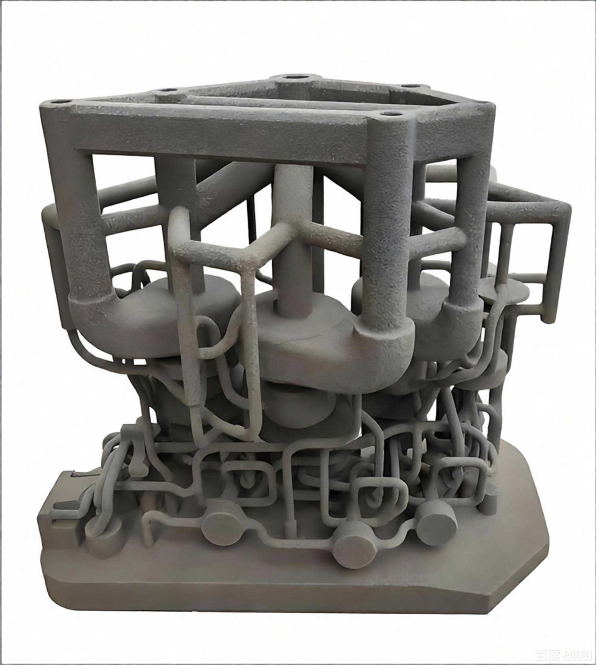
The sand molds were fabricated using a commercial SLS rapid prototyping machine. This system consists of a computer control unit, a main process chamber, a laser cooling system, an electrical system, and auxiliary equipment. The maximum build volume of the machine is 1000 × 1000 × 600 mm, with a typical layer thickness ranging from 0.1 to 0.35 mm. The process begins with creating a CAD model of the part, which is then converted to an STL file format. The build orientation is selected to minimize the number of layers and to place critical surfaces in an optimal position. The SLS system then slices the model into layers and generates the corresponding laser scanning paths. During the build, a thin layer of resin-coated sand is spread, and the laser selectively sinters the binder, bonding the sand particles together. After the build is complete, the molds and cores are removed from the build chamber, and loose sand is removed. A post-curing step is performed in a convection oven at 200 °C for 3 hours to increase the mold strength and to pre-melt the surface resin, thereby reducing the amount of gas generated during pouring. Figure 1 presents a typical example of a 3D-printed sand mold assembly for the cylinder head.
A custom-designed vacuum casting apparatus was developed for this research. The system, shown schematically in Figure 2, consists of a vacuum chamber, a vacuum pump unit, and a control system. The vacuum pump unit includes a water-ring vacuum pump, a dust collector, a pressure stabilization tank, a separator, and a control cabinet. The water-ring vacuum pump was selected due to its ability to handle dusty, humid, and high-temperature gases that may be generated during the casting process. The system is capable of maintaining a vacuum level from 0 to -0.09 MPa with a gas displacement capacity of 4.66 m³/min. The vacuum chamber provides a sealed environment for both the ladle containing the molten alloy and the sand mold. A rotating handle on the exterior of the chamber allows for controlled tilting of the ladle to pour the molten metal into the mold after the desired vacuum level is achieved.
The experimental procedure for the vacuum casting process is as follows. First, the sand molds and cores are assembled in the proper sequence and placed inside the vacuum chamber along with the ladle containing the prepared molten alloy. After sealing the chamber door, the vacuum pump is activated to evacuate the air from the chamber until the desired vacuum level is reached. Once the melt temperature is confirmed, the rotating handle is operated to tilt the ladle, allowing the molten alloy to fill the mold under the influence of gravity. After the melt has solidified, the vacuum is released, and the casting is allowed to cool under atmospheric pressure before being removed from the chamber.
2.3 Experimental Procedures
Two types of test specimen geometries were used to evaluate the casting process. The first specimen type was a rectangular plate with a length of 260 mm and two different wall thicknesses: 3 mm and 12 mm. This specimen was used to evaluate the filling capacity of the alloy under different vacuum levels. The second specimen type was a cylindrical tensile test bar with a diameter of 12 mm, designed in accordance with the GB/T 228-2002 standard. This specimen was used to evaluate the combined effects of vacuum level and pouring temperature on the mechanical properties and microstructure of the alloy.
The AC4B alloy was melted in a resistance furnace. The charge consisted of primary aluminum ingots and a maximum of 30% returns. After melting, the melt was refined using a flux and then degassed using a rotary degassing unit with nitrogen gas at a rotation speed of 260 rpm for 15 minutes. Following degassing, the melt was allowed to stand, and any remaining dross was removed. The vacuum casting experiments were performed using the custom-built apparatus described above.
To investigate the effect of vacuum level on casting quality, a series of experiments was conducted at a constant pouring temperature of 710 °C, with vacuum levels of 0 (atmospheric pressure), -0.02 MPa, -0.04 MPa, and -0.06 MPa. The plate specimens with both wall thicknesses were cast under each vacuum level. The filling length of the specimens was recorded, and the density and porosity of the castings were determined.
To investigate the effect of pouring temperature, experiments were conducted at a constant vacuum level of -0.04 MPa, with pouring temperatures of 620 °C, 640 °C, 650 °C, and 670 °C. For comparison, a series of experiments was also conducted at atmospheric pressure (0 MPa) under the same temperature conditions. Tensile test bars were cast under each condition. The filling capability, microstructure, and tensile properties of the cast bars were analyzed.
2.4 Characterization
The density of the castings was measured using the Archimedes principle. Specimens were machined from the castings, polished, weighed in air (M₁), and then weighed when suspended in distilled water (M₂). The density (ρ) was calculated using the following formula:
$$ \rho = \frac{M_1}{M_1 – M_2} \times \rho_{water} \quad (1) $$
where ρwater is the density of distilled water (taken as 1 g/cm³).
For microstructural analysis, specimens were sectioned, mounted, and prepared using standard metallographic techniques. Grinding was performed with a series of silicon carbide papers of increasing grit, followed by polishing with a diamond suspension. The polished specimens were then etched with a suitable etchant and observed using an optical microscope.
The tensile specimens were machined from the cast bars according to the GB/T 228-2002 standard. Tensile testing was performed on a universal testing machine at a crosshead speed of 2 mm/min. The fracture surfaces of the tensile specimens were examined using scanning electron microscopy (SEM) to determine the fracture mechanisms.
Hardness measurements were conducted using a Brinell hardness tester. A steel ball with a diameter of 5 mm was pressed into the specimen surface under a load of 2452 N. The Brinell hardness (HB) was calculated using the following formula:
$$ HB = \frac{0.102 \times F}{\pi D (D – \sqrt{D^2 – d^2})} \quad (2) $$
where F is the applied load (N), D is the ball diameter (mm), and d is the indentation diameter (mm).
3. Results and Discussion
3.1 Influence of Vacuum Level on Casting Quality
3.1.1 Effect on Filling Capacity
The influence of vacuum level on the filling capacity of the alloy was assessed using the rectangular plate specimens. As illustrated in Figure 3, the filling length of the 3 mm thick plate was significantly affected by the vacuum level. At atmospheric pressure (0 MPa), the filling length was only 120 mm, which is less than half of the intended length of 260 mm. This incomplete filling is attributed to the significant backpressure of gas within the mold cavity and the increased resistance to flow caused by the surface tension of the molten alloy in thin sections.
When a vacuum of -0.02 MPa was applied, the filling length increased dramatically to 223 mm, nearly doubling the filling capacity. This substantial improvement is a direct consequence of the reduced gas backpressure within the mold cavity. As described earlier, the gas backpressure is governed by the ideal gas law:
$$ P = \frac{NkT}{V} \quad (3) $$
where P is the gas pressure, N is the number of gas molecules, k is Boltzmann’s constant, T is the temperature, and V is the gas volume. By evacuating the chamber, the initial number of gas molecules (N) in the cavity is substantially reduced, thereby lowering the backpressure and facilitating the flow of molten metal.
At a vacuum level of -0.04 MPa, the 3 mm thick plate was completely filled to its full length of 260 mm. Further increasing the vacuum to -0.06 MPa also resulted in complete filling, but the improvement compared to -0.04 MPa was marginal. Therefore, a vacuum level in the range of -0.04 to -0.06 MPa appears to be optimal for filling thin-walled castings. In contrast, the 12 mm thick plate was completely filled at all the tested vacuum levels, including atmospheric pressure, suggesting that the beneficial effects of vacuum are most pronounced for thin-sectioned castings.
3.1.2 Effect on Density and Porosity
The density of the 12 mm thick plate cast under different vacuum levels is summarized in Table 2. The density of the alloy increased consistently with increasing vacuum level. At atmospheric pressure, the average density was 2.7112 g/cm³. This increased to 2.7182 g/cm³ at -0.02 MPa, 2.7247 g/cm³ at -0.04 MPa, and reached 2.7375 g/cm³ at -0.06 MPa. The overall increase in density indicates a reduction in the volume fraction of porosity and an improvement in the soundness of the casting.
| Specimen ID | Vacuum level (MPa) | Density (g/cm³) | Average density (g/cm³) |
|---|---|---|---|
| 0-1 | 0 | 2.7080 | 2.7112 |
| 0-2 | 0 | 2.7102 | |
| 0-3 | 0 | 2.7154 | |
| 2-1 | -0.02 | 2.7168 | 2.7182 |
| 2-2 | -0.02 | 2.7146 | |
| 2-3 | -0.02 | 2.7231 | |
| 4-1 | -0.04 | 2.7211 | 2.7247 |
| 4-2 | -0.04 | 2.7237 | |
| 4-3 | -0.04 | 2.7294 | |
| 6-1 | -0.06 | 2.7376 | 2.7375 |
| 6-2 | -0.06 | 2.7375 | |
| 6-3 | -0.06 | 2.7375 |
Metallographic examination of cross-sections taken from the same location of the 12 mm plates cast at 0 MPa and -0.04 MPa provided qualitative confirmation of these density measurements. The specimen cast at atmospheric pressure exhibited numerous, relatively large, and clustered gas pores, while the specimen cast under a vacuum of -0.04 MPa showed significantly fewer, smaller, and more isolated pores. The vacuum environment promotes the following beneficial effects: (1) it reduces the partial pressure of hydrogen in the surrounding gas, thereby promoting the degassing of the molten alloy and minimizing the amount of dissolved gas available to form porosity; (2) it minimizes the aspiration of air into the melt during pouring, reducing the likelihood of entrapped gas; (3) it facilitates the escape of binder-derived gases from the sand mold, preventing their entrapment in the solidifying metal; and (4) it reduces the formation of oxide films on the melt surface, which can act as nucleation sites for porosity.
3.2 Influence of Pouring Temperature on Casting Quality
3.2.1 Effect on Filling Capacity
To further validate the advantages of vacuum-assisted filling and to determine the minimum feasible pouring temperature, cylindrical tensile test bars were cast at a constant vacuum level of -0.04 MPa and at atmospheric pressure. The pouring temperatures were varied from 620 °C to 670 °C. Figure 4 presents the casting results under these different conditions.
Under a vacuum of -0.04 MPa, the tensile test bars were completely filled at pouring temperatures of 670 °C, 650 °C, and 640 °C. Even at the lowest temperature of 620 °C, where the molten alloy was observed to be noticeably more viscous, the effective gauge section of the test bar was still completely filled, although the grip ends were not fully formed. In contrast, at atmospheric pressure, the test bar cast at 620 °C exhibited a severe misrun, with only a small portion of the gauge section filled. At 650 °C, the bar was mostly filled but with incomplete grip ends. Complete filling at atmospheric pressure was only achieved at pouring temperatures of 660 °C and 670 °C. These results demonstrate that vacuum casting can reduce the minimum pouring temperature required for complete filling by 30–50 °C compared to conventional gravity casting.
The surface tension of the molten alloy is a significant resistance to filling, especially in thin sections. The additional pressure required to overcome this resistance is given by the Laplace-Young equation:
$$ P_L = \frac{4\sigma}{\delta} \quad (4) $$
where σ is the surface tension of the liquid metal and δ is the wall thickness of the casting. For very thin walls, this pressure can be substantial. By reducing the gas backpressure within the mold, vacuum casting effectively increases the net filling pressure available to overcome this resistance, thereby enabling successful filling at lower melt superheats. This is highly beneficial, as lower pouring temperatures result in a finer and more refined microstructure and improve the mechanical properties of the casting.
3.2.2 Effect on Microstructure
The microstructures of the castings produced under a vacuum of -0.04 MPa at different pouring temperatures are presented in Figure 5. At a pouring temperature of 670 °C, the as-cast microstructure consisted primarily of coarse columnar dendrites and rosette-shaped dendrites, with well-developed secondary dendrite arms and a clear growth direction. This morphology is attributed to the high superheat and slow cooling rate, which provide ample time and thermal energy for the primary α-Al phase to grow in a directional manner.
When the pouring temperature was lowered to 650 °C, the microstructure was significantly modified. The columnar dendrites were substantially reduced in number, and the dendrites began to transition towards a more spherical morphology. The overall structure became more homogeneous, and the directional growth characteristics were less pronounced. This refinement is a result of the increased cooling rate and the higher degree of undercooling at the lower pouring temperature.
At the lowest pouring temperature of 620 °C, a larger fraction of the primary phase exhibited a spherical or globular morphology. While the structure was not fully equiaxed, the dendrites became significantly more rounded, with the dendrite walls largely disappearing. The grain size was noticeably finer. This phenomenon is explained by the fact that at pouring temperatures close to the liquidus, the effective undercooling is high, leading to a lower critical nucleation energy and a higher nucleation rate. The numerous nuclei that form quickly impinge upon each other, restricting dendritic growth and promoting a more globular microstructure.
The pouring temperature also had a significant effect on the formation of casting defects. At a high pouring temperature of 670 °C, the gravity-cast specimens exhibited a considerable amount of dispersed pinhole porosity. This porosity is primarily due to hydrogen: the solubility of hydrogen in aluminum increases with temperature. During solidification, the rapid decrease in solubility forces hydrogen out of solution, forming gas bubbles that are trapped in the solidifying structure if they are unable to escape. The higher the pouring temperature, the greater the initial hydrogen content and the slower the cooling rate, which provides more time for hydrogen to be rejected and to nucleate pinholes. In contrast, the castings produced under vacuum at the same temperature showed virtually no pinhole porosity. The reduced hydrogen partial pressure in the vacuum environment promotes the degassing of the melt before pouring, significantly reducing the potential for pinhole formation. Severe macrosegregation was observed in both vacuum and gravity castings at the high pouring temperature of 670 °C, which is linked to the enhanced dendritic growth and the restricted diffusion of solute in the interdendritic liquid.
3.2.3 Effect on Tensile Properties
Figure 6 shows the tensile strength of the castings as a function of pouring temperature for the vacuum-cast condition. A clear trend of increasing tensile strength with decreasing pouring temperature is observed. The most significant increase occurs when the pouring temperature is lowered to 640 °C. This improvement in mechanical properties is directly related to the refinement of the microstructure and the transition from coarse columnar dendrites to a finer, more globular morphology, in accordance with the Hall-Petch relationship.
SEM analysis of the fracture surfaces provided further insight into the deformation and fracture behavior. At a pouring temperature of 670 °C, the fracture surface exhibited characteristic features of a quasi-cleavage fracture: a mixture of relatively flat cleavage facets connected by tearing ridges and some shallow dimples. This indicates a relatively brittle fracture mode, consistent with the coarse dendritic microstructure. In contrast, at the lowest pouring temperature of 620 °C, the fracture surface displayed a much more ductile appearance, characterized by a high density of fine and deep equiaxed dimples, which is characteristic of a microvoid coalescence fracture mechanism. This indicates improved ductility associated with the finer and more globular microstructure. The results underscore the importance of controlling the pouring temperature to achieve an optimal balance between filling capacity, microstructural refinement, and mechanical performance.
3.3 Validation with Cylinder Head Prototype
Based on the promising results obtained from the test specimens, the optimized vacuum casting process was applied to the production of a full-scale cylinder head prototype using a 3D-printed sand mold. The complex cylinder head geometry, with a nominal wall thickness of approximately 5 mm and minimum sections of 2 mm, presented an ideal validation case for the developed technology, as this geometry is representative of complex thin-walled castings that are challenging to produce by conventional gravity casting. The internal cavities for the water jacket, intake and exhaust ports, and oil galleries were formed by a set of 3D printed sand cores, while the external geometry was defined by the sand mold. The mold assembly was placed in the vacuum chamber, and casting was performed at a vacuum level of -0.04 MPa and a pouring temperature of 710 °C.
Visual inspection of the resulting cylinder head casting, as shown in Figure 7, revealed a complete filling of all features, including the thin-walled sections. The casting was free from defects such as misruns, cold shuts, and flash. A pressure test conducted on the water jacket and oil passages did not reveal any leakage. Longitudinal sectioning of the casting confirmed the complete elimination of the macro gas porosity that had been present near the intake and exhaust ports in castings produced by gravity casting. The shrinkage porosity previously observed in the thicker sections near the tappet holes was also significantly reduced.
Table 3 presents the secondary dendrite arm spacing (SDAS) measured at different locations of the cylinder head. The SDAS at the combustion chamber surface was 50 μm, followed by 56 μm near the water jacket, and 63 μm at the camshaft side. This systematic variation in SDAS indicates that the casting solidified in a progressive direction, from the combustion chamber surface to the camshaft side. This is a highly desirable solidification pattern, as it enables efficient feeding of the solidifying metal and minimizes the risk of shrinkage porosity. This directional solidification was promoted by the placement of the risers on the camshaft side of the casting and the use of a chiller effect at the combustion chamber surface, which was further enhanced by the vacuum environment that promoted excellent thermal contact between the melt and the mold surface. According to the Furer-Wunderlin model, the SDAS is inversely proportional to the cooling rate.
| Location | SDAS (μm) |
|---|---|
| Combustion chamber surface | 50 |
| Near water jacket | 56 |
| Camshaft side | 63 |
Metallographic comparison of the combustion chamber surface between the vacuum-cast and gravity-cast cylinder heads revealed a finer and more uniform microstructure in the vacuum-cast component. Additionally, the vacuum-cast component was devoid of the pinhole porosity that was present in the gravity-cast counterpart. This confirms the beneficial effect of vacuum in producing high-quality aluminum alloy castings.
The results of the tensile and hardness tests performed on specimens extracted from different sections of the cylinder head are summarized in Table 4 and Table 5. The vacuum-cast cylinder head exhibited an ultimate tensile strength (UTS) of 332 MPa at the combustion chamber surface, which exceeds the specified technical requirement of 245 MPa. The UTS was progressively lower at increasing distances from the combustion chamber, consistent with the measured SDAS values. The hardness of the combustion chamber surface was 115 HB, and the camshaft side surface was 108 HB, both of which fall within the specified ranges of 95–115 HB and 90–110 HB, respectively. The density of the samples from the vacuum-cast cylinder head was also higher than that of the gravity-cast counterpart, particularly around the water jacket, indicating reduced porosity in these critical areas.
| Location | Ultimate tensile strength, vacuum cast (MPa) | Ultimate tensile strength, gravity cast (MPa) |
|---|---|---|
| Combustion chamber surface | 332 | 318 |
| Vertical section (near camshaft) | 305 | 290 |
| Camshaft side | 298 | 285 |
| Location | Brinell hardness, vacuum cast (HB) | Brinell hardness, gravity cast (HB) |
|---|---|---|
| Combustion chamber surface | 115 | 108 |
| Camshaft side | 108 | 102 |
4. Conclusion
This research successfully demonstrated the viability of a combined process of 3D sand printing and vacuum casting for the rapid production of high-quality complex thin-walled aluminum alloy castings, specifically a cylinder head. The following conclusions can be drawn from this investigation:
(1) The developed vacuum casting apparatus and process enabled the production of sound castings, with the vacuum environment significantly reducing the gas backpressure within the mold cavity, thereby enhancing the filling capacity of the molten alloy. This effect was particularly pronounced for thin-walled sections. A vacuum level in the range of -0.04 to -0.06 MPa was identified as the optimal process window for this application.
(2) The vacuum environment was also instrumental in improving the internal quality of the castings. The density of the test specimens increased with increasing vacuum level, while the volume fraction and size of pores were substantially reduced. This is attributed to enhanced degassing of the melt, reduced aspiration of gas during filling, and improved escape of binder-derived gases from the sand mold.
(3) The vacuum casting process allowed for a 30–50 °C reduction in the pouring temperature compared to conventional gravity casting, while still achieving complete mold filling. Lowering the pouring temperature was found to be highly beneficial, as it refined the as-cast microstructure, promoting a transition from coarse columnar to fine globular structures, which in turn enhanced the tensile strength and ductility of the castings.
(4) The full-scale cylinder head prototype was successfully produced using 3D-printed sand molds and the vacuum casting process with a vacuum of -0.04 MPa and a pouring temperature of 710 °C. The casting was free from the common gravity casting defects, such as gas porosity and shrinkage porosity. It exhibited a desirable progressive solidification pattern, as evidenced by a graded secondary dendrite arm spacing (50 to 63 μm) from the combustion chamber surface to the camshaft side. The mechanical properties, including ultimate tensile strength (up to 332 MPa) and hardness, exceeded the specified technical requirements for the cylinder head.
(5) The integration of 3D printing for the fabrication of sand molds and cores with vacuum casting technology presents a powerful approach for accelerating product development, reducing costs, and delivering high-integrity complex thin-walled aluminum alloy castings, particularly for automotive engine components such as cylinder heads. The 3d printing sand casting method is particularly effective when combined with vacuum assistance. This research has established a reliable process basis and provides a theoretical and practical reference for the foundry industry. The combination of 3d printing sand casting and controlled vacuum conditions significantly expands the process capability for producing intricate components with improved consistency.
5. Recommendations and Future Work
While this research has successfully validated the core concept, several areas could be explored to further enhance the process and its applicability. Future research could focus on the development of a more automated and instrumented vacuum casting system to allow for in-situ monitoring of melt temperature, mold filling, and solidification progress. Additionally, the application of a pressure phase after filling, known as vacuum-assisted counter-pressure casting, could be investigated to further enhance the feeding of the casting during solidification and to improve the mechanical properties, particularly in thicker sections. Computational fluid dynamics and solidification modeling could be employed to optimize the gating and risering system for vacuum casting and to predict the formation of defects under various process conditions. Furthermore, the influence of degassing parameters and the use of grain refiners in combination with the vacuum process could be explored for further microstructural refinement.