
The traditional foundry industry, with a history spanning thousands of years, is now facing the challenges of a new technological revolution. Sand casting foundry, as a fundamental manufacturing process, plays a critical role in the national economy. In my research, I aimed to address the severe lag in secondary development of CAD technologies within the sand casting foundry sector. This paper presents a comprehensive CAD system specifically designed for shell-type parts manufactured through sand casting foundry. The system leverages the power of Unigraphics (UG) as a development platform, combined with Visual C++ and database technologies, to automate the design of casting processes, including gating systems, riser systems, and process parameters. Additionally, I conducted a rapid prototyping experiment on a fire hydrant cover to explore the integration of CAD/CAE/CAM with rapid prototype manufacturing (RPM). This work demonstrates significant improvements in design efficiency, accuracy, and the progression towards intelligent and integrated casting process design.
1. Introduction
The application of CAD technology in the manufacturing industry has revolutionized product design and development, significantly shortening design cycles and enhancing market competitiveness. However, within the sand casting foundry industry, the adoption rate of CAD remains relatively low, and the crucial step of secondary development has been severely lagging. Traditional sand casting foundry design heavily relies on manual experience and two-dimensional drawings, which leads to inefficiencies, poor visualization, and difficulties in extracting process parameters. To overcome these shortcomings, I developed a specialized CAD system tailored for shell-type parts produced by sand casting foundry. This system aims to provide casting engineers with an intuitive, three-dimensional, and intelligent design environment.
The primary objectives of this research include: developing a user-friendly CAD system for sand casting foundry, creating sub-systems for process parameter design, riser design and calculation, and gating system design and calculation, and exploring the combination of the CAD system with rapid prototyping technology for rapid mold making. The entire system is built upon the UG platform, using its powerful modeling capabilities and open application programming interface (API).
2. Overall System Design and Key Technologies
2.1 Development Platform Selection
For secondary development, selecting the right platform software is paramount. I considered several factors: functional capabilities, user base, openness to secondary development, and cross-platform compatibility. After thorough evaluation, I selected Unigraphics (UG NX 3.0) as the foundational CAD/CAE/CAM platform. UG provides robust solid modeling, assembly, finite element analysis, and manufacturing capabilities, making it a preferred tool in aerospace, automotive, and mold industries. Moreover, UG offers a rich set of development tools, including UG/Open API, UG/Open MenuScript, UG/Open UIStyler, and UG/Open GRIP, which are essential for creating customized applications. My system integrates UG with Microsoft Visual C++ 6.0 and Microsoft Access 2000 as the database, creating an efficient and seamless development environment.
2.2 System Requirement Analysis
The design process for sand casting foundry is complex and involves multiple stages. Traditional methods proceed from part drawings to process design and finally to process documents. Key tasks include: analyzing the casting structure, determining casting methods, selecting parting surfaces, defining process parameters (such as machining allowances, shrinkage, draft angles), designing gating and riser systems, and creating process drawings. To meet these requirements, my system adopts a modular architecture, as illustrated in Table 2.1, which describes the main functional modules of the developed system.
| Module | Function |
|---|---|
| Product Model Input | Importing 3D part models into the design environment. |
| System Initialization | Setting up project databases and acquiring part information. |
| Process Parameter Design | Determining wall thickness, holes, shrinkage, draft, and machining allowances. |
| Riser System Design | Calculating riser dimensions and creating 3D riser models. |
| Gating System Design | Computing choke area, designing runners, gates, and sprues, and generating 3D models. |
This modular structure reduces programming complexity and improves maintainability. It also allows for easy expansion, for example, adding flasks design modules when needed.
2.3 Key Development Technologies
2.3.1 Development Tools
UG offers two main secondary development languages: GRIP and UFUNC (User Function). GRIP is a simpler, interpreted language but lacks advanced data processing capabilities. UFUNC, on the other hand, is a comprehensive C/C++ API that provides access to nearly all UG operations. I chose to combine UG/Open API and UG/Open C++ for maximum flexibility and power. This approach allows me to leverage object-oriented programming and integrate seamlessly with external databases and computational libraries.
2.3.2 3D Modeling Function Realization
In the sand casting foundry CAD system, creating and modifying 3D models based on design calculations is a core requirement. I classified the modeling tasks into several categories:
- Model modification: For adding machining allowances, the system analyzes the selected face and creates a new solid by offsetting along the face normal.
- Fully constrained simple geometry: For risers and gating components, all dimensions are driven by parameters, and the system generates the 3D model through predefined feature-based functions.
- Complex geometry: For shapes like spherical risers, building a graphical library and invoking it is more efficient than programming every detail.
- Standard parts: Combining a part library with programmatic parameter adjustment to generate standard parts (e.g., locating pins, core boxes) with custom dimensions.
2.3.3 Interactive Interface and Menu Integration
An excellent user interface is crucial for user acceptance. I used UG/Open UIStyler to design dialog boxes that are consistent with UG’s native style. This tool provides drag-and-drop controls and automatically generates code templates, which greatly accelerates development. For integration, I used UG/Open MenuScript to create custom pull-down menus. The menu script file (e.g., cavity.men) is placed in the startup directory to be loaded when UG launches. An example of the menu structure is shown in Table 3.1.
| Menu Label | Action |
|---|---|
| 砂型铸造 (Sand Casting) | Cascade menu |
| Load Model | Activates file loading function |
| Shell Type Parts | Activates shell part design module |
| Shaft Type Parts | Activates shaft part design module |
| Disk Type Parts | Activates disk part design module |
2.3.4 Database and Interface Technology
The database stores casting process data, such as standard riser dimensions, gating recommendations, and material properties. I utilized C++ with DAO (Data Access Objects) to connect to the Microsoft Access database. The architecture involves an MFC DLL (let’s call it B.DLL) that wraps database access, and a UFUNC DLL (A.DLL) that handles UG-specific operations and calls B.DLL. This separation permits robust communication between the UG environment and the data layer. The following code snippet illustrates the skeleton of the UIStyler callback that saves data to the database:
int CHANGEES_apply_cb(int dialog_id, void * client_data, UF_STYLER_item_value_type_p_t callback_data)
{
    if (UF_initialize() != 0) return (UF_UI_CB_CONTINUE_DIALOG);
    CUgResource m_PSet;
    m_PSet.Open();
    // ... process parameters and store them ...
    m_PSet.Close();
    UF_terminate();
    return (UF_UI_CB_CONTINUE_DIALOG);
}
3. System Development under the UG Environment
3.1 Development Environment Configuration
Before coding, I configured both UG and Visual C++ environments. For UG, I changed the default unit to metric by editing the ugii_env.dat file. I then created a folder (e.g., D:\ugapi) with two subfolders: application (for .dlg and .bmp files) and startup (for .men and .tbr files). An environment variable UGII_USER_DIR was set to this folder to ensure UG loads the custom applications.
For Visual C++ 6.0, I registered the UG/Open Wizard template by copying ugopen_v18.awx and ugopen_v18.hlp to the VC++ template directory. I then created a new Win32 Dynamic-Link Library project, linked against libufun.lib and libugopenint.lib, and added the UG include and library paths to the project settings.
3.2 Program Framework
The main program entry point is the ufsta() function. In this function, I called UF_MB_add_styler_actions to associate the UIStyler dialog with the menu. The basic skeleton is shown below:
extern void ufsta(char *param, int *retcode, int rlen)
{
    int error_code;
    if ((error_code = UF_initialize()) != 0)
        return;
    if ((error_code = UF_MB_add_styler_actions(actions)) != 0)
    {
        char fail_message[133];
        UF_get_fail_message(error_code, fail_message);
        printf("%s\n", fail_message);
    }
    UF_terminate();
    return;
}
3.3 Key Implementation Routines
3.3.1 Feature Recognition
To identify faces and edges for operations such as draft angle detection, I implemented functions to query topological data. For instance, UF_MODL_ask_face_edges returns the edges of a face. To let the user select faces interactively, I used UF_UI_select_with_class_dialog. The code for iterating through selected faces and collecting them into a list is:
while (response == UF_UI_BACK)
{
    UF_UI_select_with_class_dialog("Please choose body", "Choose body",
        UF_UI_SEL_SCOPE_WORK_PART, NULL, &select_count, &object);
    // Highlight selected objects
    for (i=0; i<select_count; i++)
        UF_DISP_set_highlight(object[i], 0);
    if (response == UF_UI_CANCEL)
        return 0;
}
UF_CALL(UF_MODL_create_list(&face_list));
for (j=0; j<select_count; j++)
{
    UF_CALL(UF_MODL_ask_body_faces(object[j], &face_list));
}
UF_free(object);
3.3.2 Database Connectivity
As discussed, I combined UFUNC DLL and MFC DLL. The MFC DLL provides a C++ class CUgResource to handle DAO operations. The UFUNC DLL calls exported functions from the MFC DLL to store or retrieve process parameters. This method allowed me to keep the UG UI responsive while the database operations are executed in a separate module.
4. Development of the Casting Process CAD System
4.1 System Initialization
Before starting the process design, the system initializes a project. This includes:
- Creating a project directory for saving design information and intermediate results.
- Collecting part information (name, material, designer, date) and storing it in the database.
- Copying the part model into the project directory and loading it into the current UG session.
4.2 Determination of Main Process Parameters
The main process parameters are: minimum wall thickness, minimum cast holes, shrinkage rate, draft angle, and machining allowance. The relationships are shown in Table 4.1.
| Parameter | Function |
|---|---|
| Minimum wall thickness | Determines the feasibility of filling thin sections. |
| Minimum cast hole | Determines whether holes can be directly cast or must be machined. |
| Draft angle | Facilitates removal of the pattern from the mold. |
| Shrinkage rate | Compensates for metal contraction during solidification. |
| Machining allowance | Extra metal on surfaces that will be machined. |
I implemented a user interface (Figure 4.1 in the original thesis) where the user selects the casting material, and the system automatically recognizes existing holes, determines whether they are less than the minimum cast hole diameter, and then fills them with a cylinder solid. For machining allowance, the user selects a surface and the system, after analyzing its geometry, suggests an allowance based on database rules. The allowance is then added via an offset or extrusion operation.
4.2.1 Formula for Shrinkage Rate
The shrinkage rate \(K\) is defined by:
$$ K = \frac{L_{pattern} – L_{casting}}{L_{casting}} \times 100\% \tag{4-1} $$
where \(L_{pattern}\) is the pattern dimension and \(L_{casting}\) is the casting dimension. Because shrinkage is affected by many factors, the system provides a reference range and instructs users to apply it using UG’s Scale Body function, which supports uniform or non-uniform scaling.
4.3 Riser Design Module
Riser design aims to feed the casting during solidification to prevent shrinkage defects. For gray iron and ductile iron, the graphite expansion during eutectic solidification can partially compensate for shrinkage. I implemented both standard and user-defined riser design methods. The design process is summarized in Figure 4.2 (not reproducced here). The core calculation is the modulus method, defined as:
$$ M = \frac{V}{S} \tag{4-2} $$
where \(M\) is the modulus (in cm), \(V\) is the volume (cm³), and \(S\) is the effective cooling surface area (cm²). For a complex casting, I split it into simple geometric components, compute the modulus of each, and identify the critical component that governs solidification.
Figure 4.2 – Riser design structure (omitted). The system provides two riser forms: standard risers from the factory database and custom risers defined by the user. The standard riser database contains dimensions and moduli for various riser types. The user inputs the required modulus, and the system queries the database for a compatible riser. The 3D geometry of the standard riser is loaded from a pre-built graphics library. For custom risers, the user inputs all dimensions, and the system calculates the modulus and generates the model parametrically.
4.4 Gating System Design Module
The gating system includes the sprue, sprue well, runner, and ingates. The design process follows a systematic approach:
- Determine the gating system type and layout.
- Calculate the total weight of metal (including the casting, runners, and risers).
- Determine the pouring time and effective static head.
- Calculate the choke area using the hydraulic formula:
$$ F_{choke} = \frac{w}{\mu \cdot t \cdot \sqrt{2g H_p}} \tag{4-3} $$
where \(F_{choke}\) is the choke cross-section area (cm²), \(w\) is the total metal weight (kg), \(\mu\) is the flow coefficient, \(t\) is the pouring time (s), \(g\) is the gravitational acceleration (cm/s²), and \(H_p\) is the effective static head (cm).
For gray iron, pouring time can be taken from empirical tables, e.g., for weights between 15–20 kg, \(t\) is approximately 8 seconds. The flow coefficient \(\mu\) is selected based on the gating system complexity: 0.76 for two-element systems, 0.58 for three-element, and 0.48 for four-element systems. The effective static head is calculated from:
$$ H_p = H_0 – \frac{P^2}{2C} \tag{4-4} $$
where \(H_0\) is the height of metal above the ingate, \(P\) is the height of the casting above the ingate, and \(C\) is the total height of the casting.
After determining the choke area, I used specific area ratios to find the cross-sections of the other components. Two types of systems are supported: semi-closed and open. The proportions are:
- Semi-closed: \(\sum F_{in} : \sum F_{runner} : \sum F_{sprue} = 3 : 8 : 4\)
- Open: \(\sum F_{in} : \sum F_{runner} : \sum F_{choke} : \sum F_{sprue} = 1 : 0.7 : 0.4 : 0.7\)
In the gating design user interface, after the choke area is computed, the system calculates the individual cross-sectional areas. For the ingates, the factory has a standard series of trapezoidal gates, stored in the database. The user chooses the appropriate gate shape and size. The system then creates a 3D model of the ingate using either a straight extrusion or along a predefined path. Similarly, the runner and sprue are designed and modeled with their specific cross-sections, including the sprue well.
5. Application Example: Fire Hydrant Cover Design
5.1 Production Conditions and Technical Requirements
The selected part is a fire hydrant cover, produced as a single piece. The material is gray iron HT100. The part’s main dimensions are 238 mm × 238 mm × 140 mm, with a mass of approximately 8 kg. The casting must be free from shrinkage defects, porosity, sand voids, and surface defects. The pouring temperature should be around 1400–1450 °C.
5.2 Casting Process Design Using the CAD System
First, I opened the 3D model of the part in UG through the custom menu. The model is shown in Figure 5.1 (omitted). After completing the process parameter design (e.g., adding machining allowances, selecting the parting surface, applying draft angles), I obtained the final casting model, as shown in Figure 5.2 (omitted).
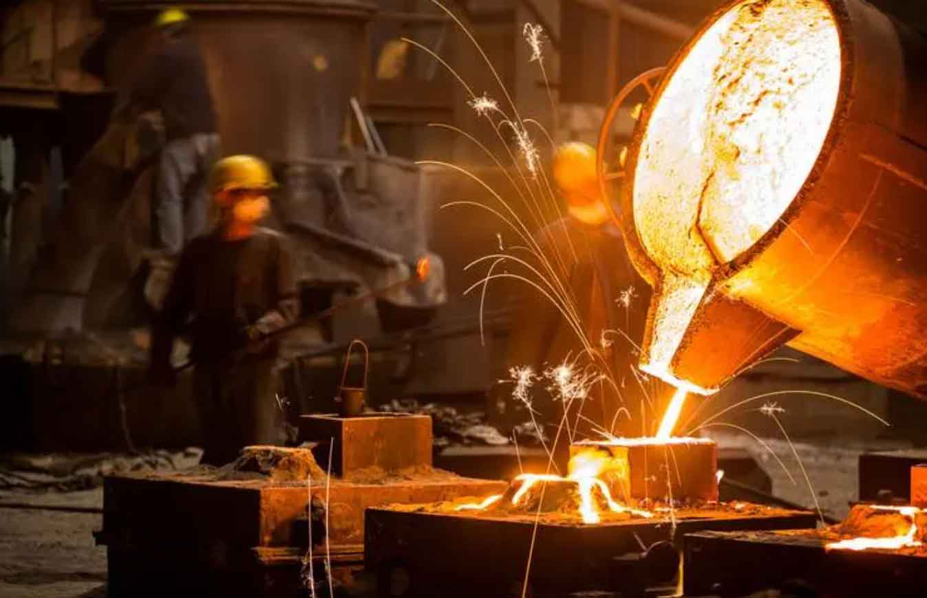
The figure above illustrates a typical sand casting foundry manufacturing scenario, demonstrating the practical relevance of the developed system.
5.2.1 Riser Design
The casting was divided into two distinct regions (components) for modulus analysis. Using the system, I calculated their volumes and cooling surface areas:
| Component | Volume (mm³) | Cooling Surface Area (mm²) | Modulus (mm) |
|---|---|---|---|
| Part 1 | 20,973.2 | 1,666.59 | 12.58 |
| Part 2 | 5,178.25 | 1,061.62 | 4.87 |
Since both moduli are greater than 0.48 cm (4.8 mm), I selected a controlled pressure riser design. The critical component is Part 2 (modulus 4.87 mm), which requires a riser. Using the riser design module, I generated the riser and its neck. The 3D model of the riser is shown in Figure 5.3 (omitted), and the assembly with the casting is shown in Figure 5.4 (omitted). The riser size was selected from the standard database with a matching modulus.
5.2.2 Gating System Design
For this example, I chose a one-casting-per-flask arrangement with a horizontal parting. The choke area was designed at the sprue. The calculation dialog returned a choke area of 3.21 cm², which corresponds to the total sprue area. Using the gating system module, I then calculated the dimensions of the runner and ingates according to the chosen area ratio. The final 3D assembly of the casting with gating and riser systems is shown in Figure 5.5 (omitted).
5.3 Production Validation
To test the design, a trial casting was made at the factory. The produced casting, shown in Figure 5.6 (omitted), was free from defects and met all technical requirements, thus validating the design and the effectiveness of the developed CAD system.
6. Rapid Prototyping Experiment for the Casting Model
6.1 Principles of Rapid Prototype Manufacturing (RPM)
RPM technology builds physical parts layer by layer directly from a 3D CAD model. In the sand casting foundry context, RPM can be used to fabricate patterns or master models quickly, bypassing traditional pattern making by hand. The main processes include SLA (Stereolithography), LOM (Laminated Object Manufacturing), SLS (Selective Laser Sintering), and FDM (Fused Deposition Modeling). A comparison is shown in Table 6.1.
| Process | Speed | Accuracy | Cost | Complexity | Material |
|---|---|---|---|---|---|
| SLA | Fast | High | High | Medium | Photo-curable resin |
| LOM | Fast | High | Low | Simple/Medium | Paper, foil |
| SLS | Slow | Medium | Medium | Complex | Wax, plastic, metal powder |
| FDM | Medium | Medium | Medium | Medium | Wax, plastic, low-melting alloy |
Because the fire hydrant cover model has relatively simple geometry and high accuracy requirements, I selected LOM for its cost-effectiveness and speed.
6.2 Prototype Fabrication Process
6.2.1 Equipment
The experiment used an HRP-III rapid prototyping machine, which consists of a numerical control system, a precision mechanical system, and a CO₂ laser. The material used is a special paper coated with hot-melt adhesive. The working principle is illustrated in Figure 6.1 (omitted).
6.2.2 Process Steps and Results
The process flow is shown in Figure 6.2 (omitted). The steps include:
- CAD model preparation: The 3D model of the fire hydrant cover was exported in STL format from UG using the File->Export->Rapid Prototyping command.
- Layered slicing: The slicing software generated cross-sectional contours at intervals of 0.1 mm.
- LOM building: The HRP-III machine automatically bonded and laser-cut each layer. The process took about 30 hours for the 140 mm high part.
- Post-processing: The paper-based part was strengthened with adhesive, sanded, and coated with lacquer to improve surface finish and moisture resistance.
The final prototype is shown in Figure 6.3 (omitted). Dimensional inspection was performed to compare the prototype with the original model. The results are summarized in Table 6.2.
| Dimension | Model | Prototype | Error (%) |
|---|---|---|---|
| Length W1 | 238 | 238.3 | 0.13 |
| Width W2 | 76 | 76.1 | 0.13 |
| Height h | 140 | 140.2 | 0.14 |
All dimensional errors are below 0.2%, confirming that the LOM process is suitable for producing casting patterns with acceptable accuracy. This experiment successfully demonstrated the integration of the developed CAD system with RPM, enabling a fast and precise path from part design to pattern fabrication in a sand casting foundry workflow.
7. Conclusions and Future Work
In this work, I successfully developed a specialized CAD system for sand casting foundry of shell-type parts. The system integrates UG, Visual C++, and database technologies to provide a user-friendly platform for casting engineers. The main achievements are summarized below.
First, the system uses a modular architecture to cover all major aspects of sand casting foundry process design, including process parameters, riser systems, and gating systems. It significantly simplifies the design process and improves efficiency by automating calculations and generating 3D models automatically.
Second, the system employs a combination of UG/Open API and UG/Open C++ for development, with UIStyler for interface design and MenuScript for seamless integration with UG. The use of DAO technology allowed easy database access, making the system data-driven and adaptable to different factory standards.
Third, the application of the system to a fire hydrant cover verified its practicality. The generated casting was successfully produced without defects, confirming the reliability of the design calculations.
Fourth, the rapid prototyping experiment confirmed that the combination of the CAD system with RPM technology can effectively replace traditional manual pattern making. This integration shortens development cycles and reduces costs, which is a significant step towards digital and intelligent sand casting foundry.
Future work should focus on the following aspects:
- Integrating the casting CAD system with CAPP/CAM for a more comprehensive digital manufacturing chain.
- Combining the system with solidification simulation to further optimize riser and gating designs.
- Expanding the system to include chill design, core design, and other auxiliary functions.
- Upgrading the database to a network-capable database system for better data sharing and collaboration.
In summary, the developed sand casting foundry CAD system provides a solid foundation for promoting the digitalization of traditional foundry enterprises, and the successful experimental results highlight its potential for broad industrial application.