
In my work on lost foam casting, I have concentrated on transforming a largely experience-driven pattern and tooling design process into a digital, parametric, and simulation-assisted workflow. The central problem is straightforward: lost foam casting offers excellent dimensional accuracy, design freedom, and environmental advantages, but its pattern design, gating layout, cooling control, and structural verification remain difficult to standardize when they depend mainly on manual judgment. I therefore developed a computer-aided design framework that combines feature-based modeling, process databases, knowledge rules, finite element analysis, and multi-objective optimization. The purpose is not simply to draw a foam pattern faster, but to make every step of lost foam casting more repeatable, traceable, and quantitatively verifiable.
Throughout this article, I use the term lost foam casting repeatedly because the method itself imposes unique constraints. The pattern must be dimensionally stable, the coating must allow controlled permeability, the gating system must fill the cavity without turbulence or collapse, and the cooling process must avoid defects such as carbon pickup, porosity, shrinkage, and distortion. In my experience, these constraints are tightly coupled. A change in wall thickness affects filling time, which affects the thermal field, which then affects stress and deformation. A CAD system for lost foam casting therefore cannot be only a geometry engine. It must connect geometry, material behavior, process rules, and optimization algorithms in one data flow.
1. Introduction and Motivation
I began with the observation that conventional lost foam casting design often follows a sequential and fragmented path. A designer creates a three-dimensional model, a process engineer adds gating and coating assumptions, and a simulation analyst later checks filling and solidification. If a problem appears, the model is revised and the cycle repeats. This sequential approach increases lead time and makes it difficult to capture the rationale behind successful designs. My goal was to create a more integrated computer-aided design environment in which lost foam casting knowledge is embedded directly into the modeling and analysis process.
The main motivations for my work can be summarized as follows. First, I wanted to reduce design cycle time. Second, I wanted to improve dimensional accuracy by linking pattern dimensions to shrinkage compensation and tooling allowances. Third, I wanted to support early-stage optimization so that stress, deformation, and filling behavior are considered before physical trials. Fourth, I wanted to build a process database and knowledge base that preserve expert rules and make them searchable. Fifth, I wanted to provide a scalable architecture that can later incorporate sensor data, digital twins, and machine learning.
| Design Challenge in Lost Foam Casting | Consequence of Traditional Practice | Digital Response in My Framework |
|---|---|---|
| Pattern shrinkage and tooling allowance | Manual compensation, trial-and-error corrections | Parametric shrinkage equations and rule-based compensation |
| Gating and filling control | Experience-driven layout, inconsistent fill quality | Automated gating area calculation and filling time estimation |
| Cooling and solidification | Late discovery of shrinkage or distortion | Transient thermal analysis and cooling curve control |
| Structural deformation | Costly physical iteration | Thermal-mechanical finite element analysis |
| Knowledge retention | Rules remain with individual engineers | SQL-based process database and Elasticsearch knowledge retrieval |
In my implementation, I treat lost foam casting as a cyber-physical design problem. The foam pattern is not an isolated object; it is the first stage of a thermal, chemical, and mechanical process. The CAD model must therefore carry process semantics. When I define a wall, a rib, a boss, or a gating channel, I associate it with process parameters such as coating permeability, sand compactability, metal static head, pouring temperature, and cooling rate. This association is what allows later automation to be meaningful rather than cosmetic.
2. Overall CAD System Framework
I designed the system as a multi-layer architecture with a presentation layer, a business logic layer, and a data layer. The presentation layer is built on a secondary development platform of a commercial CAD environment and uses a window-based user interface for parametric modeling, model editing, and visualization. The business logic layer contains the geometric modeling engine, the process calculation module, and the optimization analysis module. The data layer uses a relational database for structured process parameters and a file system or document database for three-dimensional models and analysis results.
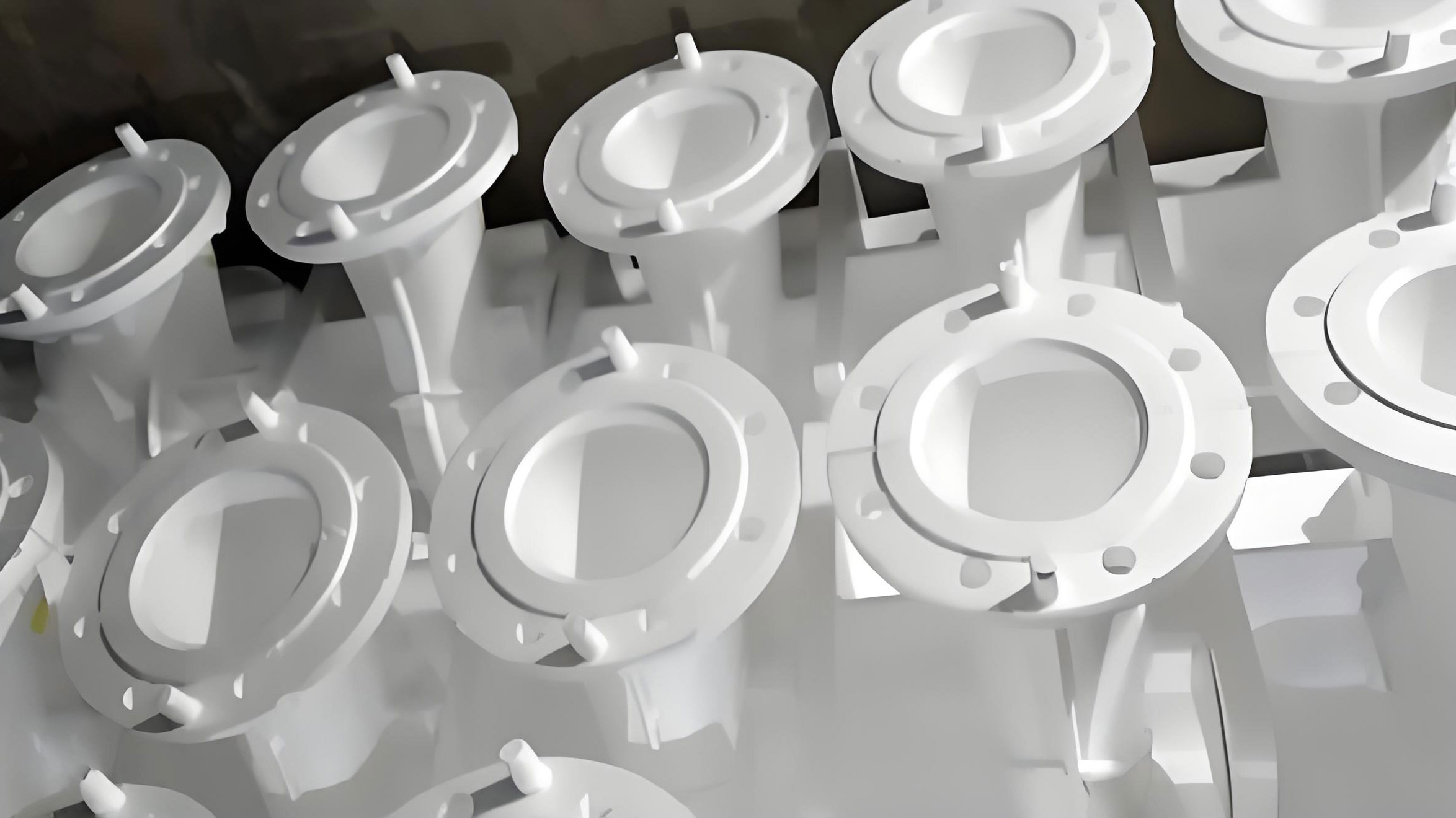
In my architecture, the geometric modeling engine is responsible for feature modeling and assembly design. The process calculation module implements algorithms for gating system design, cooling channel layout, and process parameter calculation. The optimization analysis module integrates a finite element solver through a secondary development interface and automates model import, mesh generation, solution, and result extraction. The data layer stores process parameters, model features, material properties, and design rules. The layers exchange data through standard interfaces, which keeps the system stable and extensible.
| Layer | Main Components | Function in Lost Foam Casting Design |
|---|---|---|
| Presentation layer | User interface, model visualization, parameter configuration | Allows the designer to create, inspect, and modify foam patterns and process parameters |
| Business logic layer | Geometry engine, process calculator, optimization analyzer | Generates features, calculates gating and cooling, performs finite element analysis |
| Data layer | SQL database, file system, document store | Stores structured process data, CAD files, simulation reports, and version history |
The data flow begins with user input. I ask for product type, dimensional specifications, tolerances, material grade, and production batch size. After validation, these parameters are stored in the relational database. The parametric modeling module then generates a three-dimensional model and saves it in a native CAD format. At the same time, key feature parameters are extracted and written back to the database. During process design, the system retrieves matching process parameters and calculates gating, cooling, and coating requirements. During optimization, the model is converted to a neutral format and sent to the finite element solver. The results are saved as a report and linked to the project. Multiple checkpoints ensure data completeness and consistency.
| Step | Input | Operation | Output |
|---|---|---|---|
| Parameter entry | Product type, size, tolerance, material | Validation and database storage | Validated design record |
| Model generation | Validated parameters | Feature-based parametric modeling | Native CAD model and extracted features |
| Process design | Model features, process library | Gating, cooling, and coating calculation | Process plan in XML format |
| Optimization | Neutral model, boundary conditions | Finite element analysis and optimization | Stress, deformation, and thermal results |
| Project archiving | All outputs | Version control and access management | Complete project package |
I placed strong emphasis on the interface between design and analysis. In many lost foam casting projects, the analysis model is rebuilt separately from the CAD model. This duplication introduces errors and delays. In my system, the CAD model is the master representation, and the analysis model is derived from it. Feature names, material assignments, and boundary condition zones are mapped automatically. When the designer changes a rib thickness or a fillet radius, the analysis model can be updated without manual rework.
3. Parametric Modeling of Lost Foam Patterns
3.1 Feature-Based Modeling Strategy
I adopted a feature-based hybrid modeling strategy for lost foam patterns. The first step is to construct a base feature through extrusion, revolution, or sweep. For a cylindrical lost foam pattern, the base diameter $D$ and height $H$ must satisfy a geometric constraint. I use the ratio $D/H$ to check whether the pattern can be filled and compacted properly. In my rule set, the preferred range is between 0.5 and 2.0. Outside this range, the system warns the designer and suggests a modified gating or support strategy.
After the base feature, I add functional features such as gating channels, cooling passages, ribs, bosses, and fillets. Boolean operations are used to unite or subtract material. The gating cross-sectional area $A$ is related to the model volume $V$ and the static head $h$ by a feeding relationship. I use the following equation as an initial design rule:
$$A = K \left( \frac{V}{h} \right)^{1/2}$$
where $K$ is a feeding coefficient. In my lost foam casting experiments, I found that $K$ typically lies between 0.7 and 1.2. The static head $h$ is the vertical distance from the pouring basin to the critical section of the cavity. When the model has multiple isolated thick sections, I divide the volume into zones and calculate a gating area for each zone. The system then proposes a distribution of runners and ingates.
For complex curved surfaces, I use spline-based surface modeling. Control points are adjusted to achieve the desired curvature while maintaining continuity with adjacent surfaces. I impose parent-child relationships between features so that when a base dimension changes, dependent features update automatically. This is especially important in lost foam casting because a small change in pattern geometry can alter filling behavior and cooling uniformity.
3.2 Parameter Relationships and Constraints
I built a parametric design framework on top of the CAD platform. The parameter set includes dimensional parameters, positional parameters, and process parameters. Dimensional parameters include wall thickness $t$, fillet radius $r$, rib thickness, and boss diameter. Positional parameters include array spacing $s$ and coordinates $x$, $y$, and $z$. Process parameters include shrinkage rate $\alpha$, machining allowance $\delta$, coating thickness, and sand compactability.
One of the most important relationships is the wall thickness equation. For a lost foam casting with overall dimensions $L$, $W$, and $H$, I use the following empirical relation:
$$t = \beta (LWH)^{1/3} + C$$
where $\beta$ is a process coefficient between 0.08 and 0.12, and $C$ is a base wall thickness between 3 mm and 5 mm. This equation is not a substitute for detailed solidification analysis, but it provides a rapid starting point for design. I then refine the thickness using finite element results and process rules.
Another critical relationship is shrinkage compensation. If the pattern dimension is $L_p$ and the metal shrinkage rate is $\alpha_s$, the mold cavity dimension $L_m$ should be:
$$L_m = L_p (1 + \alpha_s)$$
In lost foam casting, the pattern itself also shrinks or deforms during storage and coating. I therefore add a pattern stability factor $\alpha_p$ and a coating factor $\alpha_c$. The final pattern dimension $L_p$ becomes:
$$L_p = \frac{L_f}{(1 + \alpha_s)(1 + \alpha_p)(1 + \alpha_c)}$$
where $L_f$ is the final desired casting dimension. This equation is embedded in my parameter manager. When the user changes the final casting dimension, the pattern dimension updates automatically.
| Parameter | Symbol | Typical Range | Role in Lost Foam Casting |
|---|---|---|---|
| Feeding coefficient | $K$ | 0.7 to 1.2 | Controls gating area for feeding |
| Static head | $h$ | 100 to 500 mm | Drives filling and feeding pressure |
| Wall thickness coefficient | $\beta$ | 0.08 to 0.12 | Initial wall thickness estimation |
| Base wall thickness | $C$ | 3 to 5 mm | Minimum practical foam wall |
| Metal shrinkage rate | $\alpha_s$ | 0.5% to 2.0% | Compensates casting contraction |
| Pattern stability factor | $\alpha_p$ | 0.05% to 0.3% | Accounts for foam dimensional drift |
| Coating factor | $\alpha_c$ | 0.1% to 0.5% | Accounts for coating thickness and compaction |
I also implemented a constraint manager. The constraint manager checks that parameter changes do not violate design rules. For example, if the wall thickness becomes smaller than the minimum recommended value for a given alloy and pouring temperature, the system raises a warning. If the gating area becomes too small for the calculated filling time, the system suggests a larger runner or additional ingates. If the rib spacing exceeds a threshold that would cause collapse or distortion, the system recommends an intermediate rib.
For complex assemblies, I use parameter groups. A parameter group can contain dozens of related dimensions, such as all ribs in a frame or all cooling channels in a mold. When the user changes a global variable, the entire group updates in a controlled sequence. This reduces manual editing and ensures consistency across the lost foam casting pattern.
3.3 Model Validation and Checking
I established a multi-level model validation system. The first level is geometric consistency. I check topology completeness, surface continuity, and the absence of self-intersections. The second level is process consistency. I check wall thickness uniformity, gating area, filling time, and cooling channel clearance. The third level is simulation readiness. I check that the model can be meshed, that boundary conditions can be applied, and that material assignments are complete.
For filling behavior, I use an analytical estimate before running a full simulation. The filling time $t$ can be estimated by:
$$t = \mu (\rho g h)^{-1/2} \frac{L^2}{S}$$
where $\mu$ is the sand permeability coefficient, $\rho$ is the liquid metal density, $g$ is gravitational acceleration, $h$ is the static head, $L$ is the flow length, and $S$ is the cavity cross-sectional area. I compare this analytical estimate with the numerical simulation. If the difference exceeds a threshold, I investigate whether the gating system or the coating permeability needs adjustment.
I also check wall thickness uniformity. In my rule set, the thickness difference between adjacent walls should not exceed 20% unless a thermal gradient is intentionally designed. For critical dimensions, I define tolerance bands and let the system perform automatic inspection. Out-of-tolerance features are highlighted, and a report is generated in HTML format. The report includes a geometric parameter table, a checklist, and problem descriptions. This supports remote review and collaborative approval.
| Validation Level | Checked Items | Acceptance Criterion | Action if Failed |
|---|---|---|---|
| Geometry | Topology, continuity, intersections | No gaps, no overlaps, no self-intersections | Repair surface or rebuild feature |
| Wall thickness | Adjacent thickness variation | Difference less than 20% | Adjust ribs or wall dimensions |
| Gating | Cross-sectional area and filling time | Within process window | Modify runner or ingate size |
| Cooling | Channel spacing and clearance | No interference, uniform cooling | Reposition channels |
| Simulation readiness | Meshability and boundary zones | Mesh quality above threshold | Simplify geometry or refine zones |
After validation, the model is archived through a product data management process. The system records the design version, modification history, and associated analysis results. This is important for lost foam casting because process knowledge accumulates over time. A successful gating layout or cooling arrangement can be retrieved and reused in a future project.
4. Process Database and Knowledge Base
I constructed a process database using a relational database management system. The database contains four key tables. The first table stores process parameters such as pouring temperature, solidification time, and cooling rate. The second table stores material properties for different foam grades, such as expanded polystyrene with different densities. The third table stores standard gating and cooling system models. The fourth table stores design rules and empirical knowledge. I also built a knowledge base on top of the database to support search and recommendation.
| Database Table | Primary Fields | Purpose in Lost Foam Casting |
|---|---|---|
| Process parameter master | Pouring temperature, solidification time, cooling rate, coating permeability | Provides initial and boundary conditions for simulation |
| Material property | Foam grade, density, elastic modulus, Poisson ratio, thermal conductivity | Defines pattern behavior during filling and cooling |
| Mold structure | Standard gating models, cooling channel models, assembly templates | Accelerates repetitive design tasks |
| Process rule | Rule condition, recommended action, confidence level | Captures expert knowledge and design heuristics |
I collected expert knowledge from experienced engineers and from structured interviews. For example, a rule might state that for a large thin-wall part above 400 mm, a multi-point gating system should be used, and the runner spacing should be approximately 200 mm. Another rule might state that for a foam pattern with a wall thickness below 4 mm, the coating permeability should be increased to avoid gas entrapment. These rules are stored in a structured format so that the system can retrieve them during design.
| Foam Grade | Density (kg/m³) | Elastic Modulus (MPa) | Poisson Ratio | Thermal Conductivity (W/(m·K)) |
|---|---|---|---|---|
| EPS20 | 20 | 3.5 | 0.30 | 0.034 |
| EPS30 | 30 | 5.0 | 0.30 | 0.036 |
| EPS40 | 40 | 6.5 | 0.29 | 0.038 |
| Copolymer blend | 25 | 4.2 | 0.31 | 0.035 |
The knowledge base uses a full-text search engine. I can query by part type, size range, wall thickness, material, and defect risk. For example, when I draw a thin-wall structure, the system automatically pushes relevant process recommendations. When I select a large casting, the system retrieves previous gating designs and cooling layouts. This is not a simple file repository; it is an active design assistant. The search engine indexes CAD drawings, process photographs, simulation reports, and textual notes.
I also implemented a value evaluation module. The system tracks how often each knowledge item is used and how often it leads to a successful design. Every week, it generates a report that ranks knowledge items by usage and success rate. This helps me maintain the database and remove outdated rules. In lost foam casting, process windows change with alloy, coating, sand, and pattern density, so the knowledge base must evolve.
5. Finite Element Analysis and Structural Optimization
5.1 Thermal-Mechanical Model
I selected a typical engine block lost foam casting pattern as a case study. The pattern experiences static metal pressure, thermal gradients, and mechanical constraints during pouring and solidification. To capture these effects, I used a thermal-mechanical coupling analysis. The model was imported into a finite element environment, and material properties were assigned. For the foam pattern, I used a density of 20 kg/m³, an elastic modulus of 3.5 MPa, a Poisson ratio of 0.3, and a thermal conductivity of 0.034 W/(m·K). For the metal, I used a density of 7200 kg/m³ and a pouring velocity of 0.5 m/s.
The pressure distribution due to the liquid metal can be derived from Bernoulli-like relations. I used the following expression for the pressure at depth $h$:
$$p(h) = \rho g h + \frac{\rho v^2}{2} + p_0$$
where $\rho$ is the liquid metal density, $g$ is gravitational acceleration, $v$ is the pouring velocity, and $p_0$ is atmospheric pressure. In my model, I divided the cavity into five calculation layers and applied a corresponding pressure load to each layer. This gives a more realistic pressure distribution than a single uniform load.
For the thermal field, I used a transient heat conduction equation:
$$\rho c_p \frac{\partial T}{\partial t} = \nabla \cdot (k \nabla T) + Q$$
where $\rho$ is density, $c_p$ is specific heat capacity, $T$ is temperature, $t$ is time, $k$ is thermal conductivity, and $Q$ is a heat source term. In lost foam casting, the foam pattern decomposes and gasifies, which absorbs heat and generates gas. I represented this effect through an effective heat sink and a permeability-dependent boundary condition. The initial metal temperature was 720 °C, the pattern initial temperature was 30 °C, and the ambient temperature was 25 °C. I used convection coefficients to simulate cooling.
The thermal stress can be estimated by:
$$\sigma = E \alpha (T – T_0)$$
where $E$ is the elastic modulus, $\alpha$ is the coefficient of thermal expansion, $T$ is the current temperature, and $T_0$ is the reference temperature. This equation is a simplification, but it helps identify critical regions. I placed monitoring points at the water jacket wall, oil gallery, and main bearing saddle. The system recorded stress and deformation at each point.
5.2 Mesh Generation and Boundary Conditions
I designed a mesh strategy based on model features. For regular regions such as outer walls and bases, I used hexahedral elements with an element size of 8 mm. For complex curved regions such as water jacket corners and oil gallery turns, I used tetrahedral elements with local refinement. The minimum element size was 2 mm. I checked mesh quality with standard metrics. The orthogonal quality was required to be greater than 0.7, and the skewness was required to be less than 0.8.
| Mesh Metric | Target | Achieved |
|---|---|---|
| Total elements | Not applicable | 85,642 |
| Total nodes | Not applicable | 156,328 |
| Orthogonal quality | Greater than 0.7 | 0.74 minimum |
| Skewness | Less than 0.8 | 0.76 maximum |
| Minimum element size | 2 mm | 2 mm |
| Maximum element size | 8 mm | 8 mm in regular regions |
For boundary conditions, I fixed the bottom of the model and constrained all degrees of freedom. On the liquid metal contact surfaces, I applied the calculated pressure load and a convective heat transfer boundary with a coefficient of 5000 W/(m²·K). On the outer surfaces, I applied natural convection with a coefficient of 20 W/(m²·K). At the gating inlet, I set the metal temperature to 720 °C and defined a temperature-time curve for the cooling process. I used command-based scripting to define nonlinear contact with a friction coefficient of 0.3.
| Boundary Condition | Location | Value |
|---|---|---|
| Fixed support | Bottom surface | All degrees of freedom constrained |
| Pressure load | Metal contact surfaces | Depth-dependent from $p(h)$ |
| Convection | Metal contact surfaces | 5000 W/(m²·K) |
| Natural convection | Outer surfaces | 20 W/(m²·K) |
| Inlet temperature | Gating inlet | 720 °C |
| Contact friction |