
I have approached the development of a high-power nuclear gearbox planetary carrier as a demanding exercise in heavy-section ductile iron casting. The component is not a simple plate or housing; it is a load-bearing transmission element that directly receives and transfers large dynamic and static forces. Its design life is twenty years, and its failure would interrupt the operation of a nuclear circulating pump gearbox. Therefore, the ductile iron casting must combine high tensile strength, adequate yield strength, measurable elongation, high stiffness, dimensional stability, and internal soundness. In my development work, I treated the planetary carrier as a system problem in which chemistry, melting, spheroidization, inoculation, gating, feeding, molding, pouring, and post-treatment all influence the final ductile iron casting.
The starting point was a service requirement that exceeded the capability of a conventional QT600-3A grade ductile iron casting. Earlier carriers made from that grade showed short service life and early failure. The failure analysis indicated that the material strength and plasticity were insufficient for the actual load spectrum. To improve reliability, the internal control target for the ductile iron casting was set as a tensile strength of at least 700 MPa and an elongation of at least 5%. This target is more demanding than a standard pearlitic ductile iron specification because it requires a combination of high strength and measurable ductility in a thick-walled casting. The final ductile iron casting therefore had to be produced with a predominantly pearlitic matrix, a high nodularity, and a low level of casting defects.
I summarize the principal service and acceptance requirements in the following table. These values guided every subsequent decision, from charge selection to shakeout temperature.
| Requirement | Target or design value | Reason for control |
|---|---|---|
| Design life | 20 years | Nuclear pump gearbox reliability |
| Tensile strength | ≥700 MPa | Resistance to static and dynamic loading |
| Yield strength | As high as practical with ductility | Prevent plastic deformation under peak torque |
| Elongation | ≥5% | Damage tolerance and plasticity |
| Matrix | Pearlite dominant | Strength with acceptable toughness |
| Nodularity | ≥90% | Consistent mechanical properties |
| Internal defects | No harmful shrinkage or porosity | Fatigue and structural integrity |
The planetary carrier is a large ductile iron casting with an outline size of approximately 1280 mm in diameter and 700 mm in height. Its main wall thickness is between 100 mm and 115 mm, while the four columns reach a maximum thickness of more than 210 mm. The casting mass is about 2400 kg. These dimensions place the component in the category of thick and heavy ductile iron casting, where the solidification time is long and the thermal gradients are complex. The four columns and the flange create large, dispersed hot spots. These hot spots are difficult to feed through a single riser, and they increase the risk of shrinkage cavities, dispersed porosity, graphite degeneration, and elemental segregation.
I analyzed the geometry not as a fixed drawing but as a thermal system. The modulus of a section is the ratio of its volume to its cooling surface area. For a given section, the modulus can be written as:
$$M = \frac{V}{A}$$
where \(M\) is the modulus, \(V\) is the volume, and \(A\) is the heat-dissipating surface area. For the flange and column hot spots, the calculated modulus was approximately 4.5 cm. This value is large enough to require careful feeding and sufficiently large to cause slow cooling in the center of the ductile iron casting. The solidification time can be approximated by a power law of the form:
$$t_s = K M^n$$
where \(t_s\) is the local solidification time, \(K\) is a mold and metal-dependent constant, and \(n\) is an exponent typically between 1.5 and 2.0 for cast iron in sand molds. Because the modulus of the thick sections is high, the solidification time is long. A long solidification time promotes graphite flotation, nodule degeneration, and segregation in a ductile iron casting unless the chemistry and process are tightly controlled.
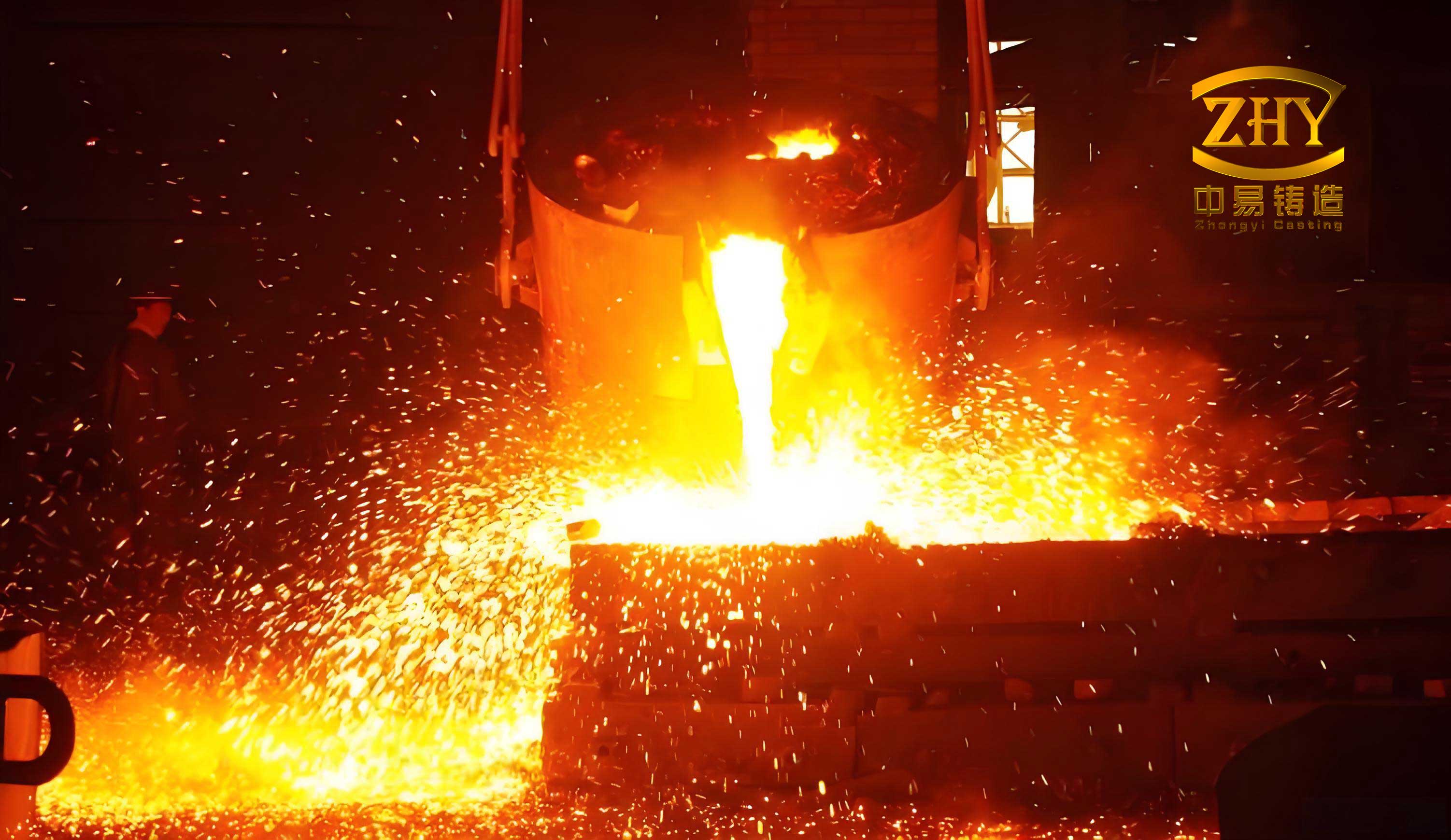
Chemical Composition Design for the Ductile Iron Casting
I based the composition design on the principle of high carbon, low silicon, low phosphorus, low sulfur, controlled magnesium, controlled rare earth, and moderate copper. The objective was to obtain a ductile iron casting that is predominantly pearlitic in the as-cast condition, with a high nodularity and a low tendency toward carbides, flake graphite, and shrinkage. The carbon content of the base iron was set at 3.5% to 3.7%. Within this range, carbon promotes graphitization, reduces the chilling tendency, improves magnesium recovery, increases the roundness of graphite nodules, and improves fluidity. However, excessive carbon in a heavy section can cause graphite flotation because the density of graphite is lower than that of liquid iron. Graphite flotation is especially dangerous in a thick ductile iron casting because it creates a carbon-rich layer near the upper surfaces and a carbon-deficient region in the lower and central parts.
The carbon equivalent is a useful first-order control parameter. I used the conventional expression for cast iron:
$$CE = C + \frac{Si}{3} + \frac{P}{3}$$
or, when phosphorus is very low, the simplified form:
$$CE \approx C + \frac{Si}{3}$$
I controlled the carbon equivalent after spheroidization and inoculation in the range of 4.3% to 4.4%. This range provides good castability while limiting graphite flotation. The carbon equivalent must be evaluated together with the actual section modulus because a carbon equivalent that is safe for a thin ductile iron casting can be unsafe for a heavy section. For the present planetary carrier, the combination of 3.5% to 3.7% carbon in the base iron and 2.0% to 2.3% silicon after treatment gave a carbon equivalent that promoted graphitization without excessive flotation.
Silicon is a strong graphitizing element, but it also affects the matrix. In an as-cast pearlitic ductile iron casting, a high silicon content increases ferrite and lowers strength. A very low silicon content, on the other hand, increases the risk of free cementite and reduces ductility. I therefore specified the silicon content after spheroidization and inoculation as 2.0% to 2.3%. This range balances graphitization, matrix control, and mechanical property reproducibility. The final silicon content is not simply the charge silicon; it includes silicon from the spheroidizing agent, the inoculant, and any late stream inoculation. I accounted for all of these sources in the charge calculation.
Manganese is a pearlite-stabilizing element. A moderate manganese addition increases strength, hardness, and wear resistance. However, manganese has a strong segregation tendency in thick ductile iron casting. At high levels, it forms intercellular network carbides and lowers toughness and elongation. I therefore limited manganese to less than 0.5%. In the actual production heat, the manganese content was 0.23%, which is well below the upper limit and favors ductility.
Sulfur and phosphorus are undesirable in a high-quality ductile iron casting. Sulfur reacts with magnesium and rare earth elements to form sulfides, which consume spheroidizing elements, reduce nodularity, and increase slag and dross. Sulfur also increases the risk of blowholes, subsurface porosity, and hot tears. I specified sulfur below 0.02%. Phosphorus has low solubility in iron and tends to form phosphorus eutectic at cell boundaries. This eutectic lowers plasticity, toughness, and strength and increases cold cracking susceptibility. I specified phosphorus below 0.03%. In the final composition, sulfur was 0.008% and phosphorus was 0.018%, both comfortably within the target.
Magnesium is the primary spheroidizing element. It converts flake graphite into nodular graphite, but excess magnesium increases the chilling tendency, promotes dross, and can cause exploded graphite. I specified residual magnesium in the range of 0.04% to 0.06%. Rare earth elements assist spheroidization, neutralize harmful trace elements, and purify the iron, but excess rare earth can promote carbides and reduce nodularity. I specified residual rare earth below 0.02%. The low rare earth level is consistent with modern ductile iron casting practice for heavy sections.
Copper is a useful alloying element for as-cast pearlitic ductile iron. It promotes graphitization during eutectic solidification and stabilizes and refines pearlite during eutectoid transformation. It also strengthens the matrix without the severe segregation tendency of manganese. I specified copper in the range of 0.5% to 0.8%. In the actual heat, copper was 0.56%, which produced a pearlite-dominant matrix while maintaining acceptable elongation.
The designed chemical composition range is shown in the following table. I used this as the controlling specification for the ductile iron casting.
| Element | Control range (wt.%) | Function in the ductile iron casting |
|---|---|---|
| C in base iron | 3.5 to 3.7 | Graphitization, fluidity, nodule count |
| Si after treatment | 2.0 to 2.3 | Graphitization, matrix balance |
| Mn | <0.5 | Pearlite stabilization, strength |
| S | <0.02 | Reduce sulfide formation and dross |
| P | <0.03 | Reduce phosphorus eutectic |
| Mg residual | 0.04 to 0.06 | Spheroidization |
| RE residual | <0.02 | Auxiliary spheroidization and purification |
| Cu | 0.5 to 0.8 | Pearlite formation and matrix strengthening |
I also considered trace elements such as titanium, arsenic, lead, antimony, bismuth, and aluminum. These elements can interfere with spheroidization or promote abnormal graphite. For a heavy-section ductile iron casting, even small amounts of interfering elements can accumulate in the last-to-solidify liquid and degrade nodularity. I therefore selected high-purity pig iron and clean scrap, and I maintained a low rare earth residual to neutralize minor amounts of harmful elements without creating carbides. The charge was designed to avoid excessive nitrogen and hydrogen pickup, because gas defects are difficult to eliminate in a thick section.
Gating and Feeding Design for the Ductile Iron Casting
I designed the gating system using the large-orifice discharge principle and the balanced solidification concept. The pouring time was set at 60 to 70 seconds. The gating ratio was selected as:
$$\Sigma A_{\text{runner}} : \Sigma A_{\text{choke}} : \Sigma A_{\text{sprue}} = 1.00 : 2.00 : 1.56$$
where the choke area is the controlling cross-section. The choke area was calculated as 38 cm². I used a 100 mm diameter ceramic tube for the sprue, 80 mm diameter ceramic tubes for the runners, and two 150 mm × 30 mm ceramic filters with 10 PPI in the runner system for slag and dross control. Four 40 mm diameter ceramic tube inlets were distributed uniformly around the casting so that the liquid iron entered the mold cavity in a dispersed manner. This arrangement reduced the cross-section of each individual inlet, which helped close the inlets quickly after filling and prevented iron from flowing back into the gating system during graphitic expansion.
The gating system was designed to fill the mold quickly but smoothly. A low pouring temperature and a short pouring time reduce liquid shrinkage and help avoid cold shuts. However, excessively turbulent filling can entrain air, oxide films, and slag. The ceramic filters and the dispersed inlets were intended to reduce turbulence. I also used a bottom-fill or bottom-assisted filling path so that the liquid metal rose in a controlled manner. This is important for a ductile iron casting because magnesium-treated iron is sensitive to oxidation and turbulence. The oxide films formed during turbulent filling can remain in the casting and act as initiation sites for fatigue cracks.
For feeding, I used small-neck insulating risers. The modulus of the flange and column hot spots was about 4.5 cm. I placed four 200 mm diameter necked insulating risers slightly away from the four hot spots. This arrangement provided local feeding while promoting a more uniform temperature field and simultaneous solidification. A breaker core with a 30 mm diameter was placed at the base of each riser. The breaker core controlled the liquid feeding time and made riser removal easier. The riser neck must remain open long enough to feed liquid shrinkage, but it must close before graphitic expansion causes iron to flow back from the casting into the riser. If the neck remains open too long, the expansion can push iron backward and create shrinkage porosity in the casting. If it closes too early, the hot spot may not receive enough liquid feed. The breaker core therefore acts as a thermal and hydraulic valve.
The feeding requirement can be expressed approximately as:
$$V_r = \epsilon V_c + V_s$$
where \(V_r\) is the required riser feeding volume, \(\epsilon\) is the volumetric liquid shrinkage, \(V_c\) is the casting volume that must be fed, and \(V_s\) is a safety allowance. For ductile iron, graphitic expansion can compensate for part of the liquid shrinkage, but the compensation is not uniform in a thick casting. The expansion is most effective when the mold is rigid and the casting has enough graphite expansion at the right time. A soft mold can yield and increase the apparent shrinkage. I therefore used a high-strength, high-rigidity sand mold and carefully controlled the mold hardness.
The principal gating and feeding parameters are listed in the following table.
| Parameter | Value | Purpose |
|---|---|---|
| Pouring time | 60 to 70 s | Balanced filling and shrinkage control |
| Gating ratio | 1.00 : 2.00 : 1.56 | Controlled flow and slag entrapment reduction |
| Choke area | 38 cm² | Flow rate control |
| Sprue diameter | 100 mm ceramic tube | Stable flow |
| Runner diameter | 80 mm ceramic tube | Distribution and filtration |
| Filters | 2 × 150 mm × 30 mm, 10 PPI | Slag and dross control |
| Inlets | 4 × 40 mm ceramic tubes | Dispersed filling |
| Risers | 4 × 200 mm necked insulating | Hot-spot feeding |
| Breaker cores | 30 mm diameter | Feeding time control |
Numerical Simulation of Filling and Solidification
Before production, I built a three-dimensional model of the planetary carrier, gating system, risers, and mold. I used casting simulation software to analyze the filling and solidification of the ductile iron casting. The simulation was not used as a substitute for experience; rather, it was used to compare design alternatives and identify regions where shrinkage, cold shuts, or gas entrapment might occur. The filling simulation showed that the liquid iron entered the mold cavity without severe splashing. The liquid surface rose in a stable manner. There were no obvious dead zones or abrupt changes in flow direction that would create excessive turbulence. Because the filling sequence was smooth, the risk of slag entrapment and sand erosion was reduced.
The solidification simulation showed that the feeding paths remained open during the early stages of solidification. There was no isolated liquid region inside the casting. The breaker cores at the riser necks closed the feeding channels after a suitable time, which prevented backflow of iron into the risers during graphitic expansion. The last-to-solidify regions were located near the riser necks and in the thick column sections, as expected. The simulation results are summarized in the following table.
| Simulation stage | Observed behavior | Process implication |
|---|---|---|
| Initial filling | Smooth entry, no severe splashing | Low slag entrainment risk |
| Mid filling | Stable rising front | Uniform temperature distribution |
| Final filling | Complete filling without cold shut | Adequate pouring temperature and time |
| Early solidification | Open feeding paths | Effective riser feeding |
| Mid solidification | No isolated liquid pools | Low shrinkage cavity risk |
| Late solidification | Riser neck closure before expansion backflow | Reduced dispersed porosity |
I also used the simulation to evaluate the effect of riser position. Placing the risers exactly on the hot spots often creates a large contact area and a long feeding path, which can increase the riser size and the thermal gradient. Placing them slightly away from the hot spots produced a more uniform temperature field and reduced the tendency for a localized hot spot at the riser neck. The breaker core further controlled the feeding behavior. This combined approach is important for a heavy ductile iron casting because the interaction between liquid shrinkage and graphitic expansion is complex.
The solidification time in the thick sections can be approximated by the modulus method. If the local modulus is \(M\), the feeding distance of a riser can be estimated from foundry experience and simulation. I used the following relationship as a guide:
$$L_f = k \sqrt{M}$$
where \(L_f\) is the feeding distance and \(k\) is an empirical coefficient that depends on the alloy, mold, and temperature gradient. For ductile iron, the graphitic expansion modifies the effective feeding distance, but the modulus and thermal gradient remain the primary controls. The numerical simulation provided a more detailed three-dimensional picture than any simple formula, but the formula helped me set the initial riser spacing and neck size.
Melting, Spheroidization, and Inoculation
I used a three-ton medium-frequency induction furnace to melt the charge. The charge consisted of high-purity pig iron and selected clean scrap. Copper was added to the furnace bottom in the early stage of melting as an alloying addition, which promoted uniform concentration in the liquid iron. I used an optical emission spectrometer to analyze the liquid iron and adjust the composition before tapping. The base iron was superheated to a temperature high enough to dissolve the charge completely and to allow flotation of inclusions, but not so high that it caused excessive oxidation and magnesium loss. The tapping temperature for spheroidization was controlled at 1400 to 1430 °C.
I used the covered tundish or sandwich method for spheroidization and inoculation. The spheroidizing agent was added at 1.3% of the iron mass. Its main composition was 5.68% Mg, 0.55% Al, 44.29% Si, 1.0% Ca, and 0.93% Re, with a particle size of 4 to 25 mm. The inoculant added in the ladle was a high-calcium barium inoculant at 0.4% of the iron mass. Its main composition was 1.03% Al, 72.76% Si, 1.55% Ca, and 2.35% Ba, with a particle size of 3 to 8 mm. After the spheroidization and inoculation reaction was complete, I immediately skimmed the slag to prevent sulfur reversion and covered the liquid surface with a slag conditioner to reduce oxidation.
To strengthen the inoculation effect, improve feeding, eliminate carbides, and improve the combination of strength and elongation, I added a sulfur-oxygen inoculant during pouring. The addition rate was 0.1% by stream inoculation. Its main composition was 73% Si, 1.0% Ca, 1.75% Ce, 1.0% Al, with trace sulfur and oxygen, and a particle size of 0.2 to 0.7 mm. The stream inoculation provided late nucleation sites and helped reduce the tendency for chill and carbides in the thin sections and at the mold walls. It also improved the nodule count and nodularity in the final ductile iron casting.
The treatment parameters are summarized in the following table.
| Treatment step | Parameter | Value or composition |
|---|---|---|
| Melting furnace | Capacity | 3 t induction furnace |
| Charge | Base materials | High-purity pig iron and clean scrap |
| Copper addition | Stage | Furnace bottom, early melt |
| Spheroidization | Tapping temperature | 1400 to 1430 °C |
| Spheroidizing agent | Addition rate | 1.3% of iron mass |
| Spheroidizing agent | Composition | 5.68% Mg, 0.55% Al, 44.29% Si, 1.0% Ca, 0.93% Re |
| Spheroidizing agent | Particle size | 4 to 25 mm |
| Ladle inoculant | Addition rate | 0.4% of iron mass |
| Ladle inoculant | Composition | 1.03% Al, 72.76% Si, 1.55% Ca, 2.35% Ba |
| Ladle inoculant | Particle size | 3 to 8 mm |
| Stream inoculant | Addition rate | 0.1% during pouring |
| Stream inoculant | Composition | 73% Si, 1.0% Ca, 1.75% Ce, 1.0% Al, trace S and O |
| Stream inoculant | Particle size | 0.2 to 0.7 mm |
The magnesium content in the final ductile iron casting depends on the initial magnesium addition, the sulfur content of the base iron, the oxygen content, the holding time, and the pouring time. The magnesium recovery can be expressed as:
$$\eta_{Mg} = \frac{Mg_{\text{residual}}}{Mg_{\text{added}}} \times 100\%$$
In my practice, the residual magnesium was controlled at 0.04% to 0.06%. A residual magnesium below 0.04% can lead to incomplete spheroidization and flake graphite. A residual magnesium above 0.06% can increase dross, chill, and exploded graphite. The rare earth residual was kept below 0.02% to avoid carbide formation. The combination of magnesium and rare earth must be adjusted for the sulfur and oxygen content of the base iron. A high sulfur charge consumes magnesium and rare earth and makes the residual content unpredictable. This is one reason I specified sulfur below 0.02%.
Molding, Pouring, and Post-Treatment
I used a three-box molding system with a sand box size of 1600 mm × 1600 mm × 320 mm. The parting surfaces were arranged to allow proper placement of the gating system and risers. I used sodium silicate sand to produce a high-strength, high-rigidity mold. A rigid mold is essential for a heavy ductile iron casting because graphitic expansion can deform a soft mold and increase the apparent shrinkage. The mold must restrain the expansion so that the expansion can compensate for liquid shrinkage and reduce porosity. I also designed the mold to avoid mold wall movement and cope lift. The upper mold was provided with sixteen 20 mm diameter vent holes distributed uniformly to allow gas escape during pouring. Without adequate venting, gas can be trapped and form blowholes or incomplete filling.
To prevent burn-on and improve surface quality, I coated the mold uniformly with a graphite alcohol-based coating to a thickness of about 1.5 mm. The coating reduces metal-mold reaction and makes cleaning easier. The mold was baked in a hot air oven at 240 °C for more than four hours before closing. This baking raised the mold cavity temperature to 50 to 60 °C and reduced moisture. A dry mold is important for a ductile iron casting because moisture can react with magnesium and cause gas defects.
The pouring temperature was 1350 °C, and the pouring time was 61 seconds. I used a low-temperature, fast-pour strategy to reduce liquid shrinkage and avoid cold shuts. The pouring temperature must be high enough to fill the thin sections and to allow the magnesium-treated iron to flow, but low enough to minimize shrinkage and gas pickup. After pouring, the casting was allowed to cool in the mold. I shook out the casting only after the temperature fell below 300 °C. This slow cooling reduces residual stress and avoids cracking. The post-treatment parameters are summarized in the following table.
| Process step | Parameter | Value |
|---|---|---|
| Molding | Box size | 1600 mm × 1600 mm × 320 mm |
| Molding | Number of boxes | 3 |
| Mold material | Binder system | Sodium silicate sand |
| Venting | Vent holes | 16 × 20 mm |
| Coating | Type and thickness | Graphite alcohol-based, 1.5 mm |
| Mold baking | Temperature and time | 240 °C for more than 4 h |
| Mold cavity temperature | Before pouring | 50 to 60 °C |
| Pouring | Temperature | 1350 °C |
| Pouring | Time | 61 s |
| Shakeout | Temperature | Below 300 °C |
Microstructure and Mechanical Properties of the Ductile Iron Casting
After production, I analyzed the attached cast test block. The chemical composition of the final ductile iron casting is shown in the following table. The carbon content was 3.65%, silicon was 2.04%, manganese was 0.23%, phosphorus was 0.018%, sulfur was 0.008%, copper was 0.56%, and residual magnesium was 0.05%. These values are consistent with the designed composition range. The low sulfur and phosphorus contents helped achieve a high nodularity and good ductility. The copper content produced a pearlite-dominant matrix. The residual magnesium was sufficient for spheroidization without excessive chill.
| Element | Final composition (wt.%) | Designed range (wt.%) |
|---|---|---|
| C | 3.65 | 3.5 to 3.7 |
| Si | 2.04 | 2.0 to 2.3 |
| Mn | 0.23 | <0.5 |
| P | 0.018 | <0.03 |
| S | 0.008 | <0.02 |
| Cu | 0.56 | 0.5 to 0.8 |
| Mg residual | 0.05 | 0.04 to 0.06 |
| RE residual | Below detection or very low | <0.02 |
The microstructure showed a predominantly pearlitic matrix. The nodularity was above 90%. The graphite nodules were distributed uniformly, and there was no significant evidence of flake graphite, exploded graphite, or massive carbides. A predominantly pearlitic matrix provides high strength and wear resistance. The nodularity above 90% ensures that the stress concentration at the graphite particles is reduced. In a ductile iron casting, the nodule count, nodule size, and nodularity all influence the mechanical properties. A high nodule count refines the solidification structure and improves ductility, while a uniform nodule distribution reduces the scatter in tensile properties.
The nodularity can be expressed as:
$$N = \frac{N_{VI} + N_{VII}}{N_{\text{total}}} \times 100\%$$
where \(N_{VI}\) and \(N_{VII}\) are the numbers of graphite particles with nodularity classes VI and VII, and \(N_{\text{total}}\) is the total number of graphite particles examined. The measured nodularity was greater than 90%, which satisfies the acceptance criterion. I also examined the matrix and found that the pearlite content was dominant, with a small amount of ferrite. The ferrite content must be controlled because too much ferrite lowers strength, while too little ferrite can reduce elongation. The balance obtained in this ductile iron casting was suitable for the service requirements.
I prepared round tensile specimens with a 14 mm gauge diameter. The tensile test was performed on a universal testing machine. The measured tensile strength was 797 MPa, the yield strength was 444 MPa, and the elongation was 7.0%. These values meet and exceed the internal target of at least 700 MPa tensile strength and at least 5% elongation. The yield strength of 444 MPa provides a margin against plastic deformation under peak load. The elongation of 7.0% indicates that the ductile iron casting has enough plasticity to redistribute localized stresses and resist cracking. The mechanical property results are summarized in the following table.
| Property | Measured value | Acceptance target | Result |
|---|---|---|---|
| Tensile strength | 797 MPa | ≥700 MPa | Pass |
| Yield strength | 444 MPa | As high as practical | Satisfactory |
| Elongation | 7.0% | ≥5% | Pass |
| Matrix | Pearlite dominant | Pearlite dominant | Pass |
| Nodularity | >90% | ≥90% | Pass |
The tensile specimen dimensions were selected to represent the material in the attached test block. The gauge diameter was 14 mm. The specimen was machined according to standard practice. The test results are representative of the ductile iron casting because the attached test block solidified with the casting and experienced a similar thermal history. An attached test block is preferred over a separately cast test bar for heavy ductile iron casting because it better reflects the cooling rate, nodularity, and matrix of the actual component. A separately cast test bar may cool faster and show higher strength and elongation than the casting itself. The attached test block therefore provides a more conservative and reliable assessment.
Defect Prevention and Process Robustness
I paid particular attention to the defects that commonly occur in heavy ductile iron casting: graphite flotation, graphite degeneration, shrinkage cavities, dispersed porosity, dross, slag inclusion, gas porosity, carbides, and residual stress. Each defect has a different cause, but they interact through the chemistry and thermal history. For example, a high carbon equivalent improves fluidity and graphitization but increases graphite flotation risk. A high magnesium residual improves spheroidization but increases dross and chill. A high pouring temperature improves filling but increases liquid shrinkage and gas pickup. A low pouring temperature reduces shrinkage but increases the risk of cold shuts and carbides. The process window must be balanced.
Graphite flotation occurs when graphite nodules form and rise in the liquid because their density is lower than that of the liquid iron. It is most likely in thick sections with long solidification times and high carbon equivalent. I controlled graphite flotation by limiting the carbon content in the base iron to 3.5% to 3.7%, controlling the carbon equivalent to 4.3% to 4.4%, and using a relatively low pouring temperature. I also used a rigid mold and a suitable riser arrangement to promote a uniform temperature field. The simulation and the final microstructure showed no harmful flotation.
Graphite degeneration occurs when the nodular graphite becomes irregular or flake-like in the last-to-solidify liquid. It is promoted by long solidification time, high sulfur, high oxygen, and high rare earth or magnesium residual. I controlled degeneration by keeping sulfur below 0.02%, using a low rare earth residual, and maintaining the magnesium residual in the range of 0.04% to 0.06%. I also used late stream inoculation to provide additional nucleation sites and to reduce the tendency for abnormal graphite. The final nodularity above 90% confirmed that degeneration was effectively controlled.
Shrinkage cavities and dispersed porosity are caused by inadequate feeding, mold wall movement, excessive pouring temperature, and unfavorable graphitic expansion. I used a balanced solidification design with necked insulating risers and breaker cores. The breaker cores closed the feeding channels at the proper time to prevent backflow during graphitic expansion. I also used a high-rigidity sodium silicate sand mold to restrain expansion. The numerical simulation showed that the feeding paths remained open during the critical period and that no isolated liquid regions formed. The final casting showed no harmful shrinkage defects.
Dross and slag inclusions are common in magnesium-treated ductile iron casting. They form when magnesium and rare earth react with oxygen and sulfur. I used ceramic filters in the runner system, a covered ladle, and a clean charge. I also skimmed the slag immediately after spheroidization and covered the liquid surface with a slag conditioner. The gating system was designed for smooth filling to minimize turbulence and oxide film entrainment. These measures reduced the risk of dross and slag defects.
Gas porosity can arise from moisture in the mold, excessive binder, turbulent filling, and magnesium reaction. I baked the mold at 240 °C for more than four hours, used a graphite alcohol-based coating, and provided adequate venting. The low pouring temperature and smooth filling also reduced gas entrapment. The final casting was examined and showed no significant gas defects.
Carbides can form in thin sections or in regions with high manganese, high chromium, high molybdenum, or high rare earth. They reduce ductility and machinability. I limited manganese to less than 0.5%, kept rare earth below 0.02%, and used a strong inoculation practice. The stream inoculant provided late nucleation and helped eliminate carbides. The matrix was pearlite dominant with no significant free carbides.
Residual stress can cause distortion or cracking during machining or service. It is caused by thermal gradients, phase transformations, and mold restraint. I reduced residual stress by controlling the shakeout temperature. The casting was shaken out only after the temperature fell below 300 °C. This slow cooling allowed the casting to relax stresses. The high-rigidity mold also helped reduce deformation. The final casting was dimensionally stable and suitable for subsequent machining.
The following table summarizes the main defect risks and the actions I took to control them in the ductile iron casting.
| Defect risk | Main cause | Control action |
|---|---|---|
| Graphite flotation | High C and CE, long solidification time | Limit C to 3.5-3.7%, CE to 4.3-4.4%, low pouring temperature |
| Graphite degeneration | Long solidification time, S, O, excess Mg/RE | Low S, controlled Mg, low RE, late inoculation |
| Shrinkage cavity | Inadequate feeding, mold yield, backflow | Necked risers, breaker cores, rigid mold, simulation |
| Dispersed porosity | Poor feeding, late expansion, gas | Balanced solidification, venting, dry mold |
| Dross and slag | Mg/RE reaction with O and S | Clean charge, filters, skimming, covered ladle |
| Gas porosity | Moisture, turbulence, Mg reaction | Mold baking, smooth filling, venting |
| Carbides | High Mn, RE, Cr, Mo, rapid cooling | Low Mn, low RE, strong inoculation |
| Residual stress | Thermal gradients, mold restraint | Shakeout below 300 °C, uniform cooling |
Process Window and Statistical Control
For production of a critical ductile iron casting, a single successful heat is not enough. The process must be repeatable. I therefore defined a process window for each key variable. The carbon content of the base iron should remain between 3.5% and 3.7%. The silicon after treatment should remain between 2.0% and 2.3%. The carbon equivalent should remain between 4.3% and 4.4%. The manganese should remain below 0.5%. The sulfur should remain below 0.02%. The phosphorus should remain below 0.03%. The residual magnesium should remain between 0.04% and 0.06%. The residual rare earth should remain below 0.02%. The copper should remain between 0.5% and 0.8%. The pouring temperature should remain close to 1350 °C, and the pouring time should remain between 60 and 70 seconds. The shakeout temperature should remain below 300 °C.
The process capability can be evaluated using the capability index:
$$C_p = \frac{USL – LSL}{6\sigma}$$
where \(USL\) is the upper specification limit, \(LSL\) is the lower specification limit, and \(\sigma\) is the process standard deviation. For a critical ductile iron casting, a high \(C_p\) value indicates that the process is centered and narrow relative to the specification. I used this concept to prioritize the variables that most strongly affect tensile strength and elongation. Carbon, silicon, magnesium residual, nodularity, and cooling rate were the most important. By controlling these variables, I achieved a robust process window.
I also considered the effect of section size on properties. In a thick ductile iron casting, the cooling rate varies from surface to center. The surface cools faster and may have a higher nodule count and a finer pearlite spacing. The center cools more slowly and may have coarser nodules and a slightly lower strength. The attached test block should be positioned so that its cooling rate is representative of the critical section. I placed the attached test block near a thick section to obtain conservative property data. The measured tensile strength of 797 MPa and elongation of 7.0% therefore represent the heavy section rather than an optimistic thin-section value.
Comparison with Previous Practice
Previous planetary carriers used a QT600-3A grade ductile iron casting. That grade provided a tensile strength of about 600 MPa and an elongation of about 3%. Under the actual load spectrum, the combination of strength and plasticity was insufficient. The failure was not caused by a single overload but by the accumulation of damage under cyclic loading. A higher strength alone would not solve the problem if the ductility were too low, because low ductility reduces the ability to redistribute stress at notches and defects. The target of at least 700 MPa tensile strength and at least 5% elongation was therefore a balanced requirement. The new ductile iron casting achieved 797 MPa tensile strength and 7.0% elongation, which represents a significant improvement over the previous grade.
The following table compares the previous grade with the newly developed ductile iron casting.
| Property | Previous QT600-3A | New ductile iron casting | Improvement |
|---|---|---|---|
| Tensile strength | About 600 MPa | 797 MPa | Higher strength |
| Elongation | About 3% | 7.0% | Higher ductility |
| Matrix | Mixed ferrite and pearlite | Pearlite dominant | Better strength balance |
| Nodularity | Acceptable but variable | >90% | More consistent |
| Service life | Short, early failure | Designed for 20 years | Improved reliability |
The improvement came from several factors. First, the chemistry was designed for a pearlite-dominant matrix with controlled carbon, silicon, manganese, sulfur, phosphorus, magnesium, rare earth, and copper. Second, the spheroidization and inoculation practice was optimized to achieve high nodularity and a high nodule count. Third, the gating and feeding system was designed using simulation and the balanced solidification concept. Fourth, the mold was rigid and well vented. Fifth, the pouring and shakeout temperatures were controlled to reduce shrinkage and residual stress. The combination of these measures produced a ductile iron casting that meets the demanding service requirements.
Mathematical Summary of Key Control Relationships
For a concise summary, I present the main relationships that guided the development. The carbon equivalent was controlled by:
$$CE = C + \frac{Si}{3} + \frac{P}{3}$$
The section modulus was calculated as:
$$M = \frac{V}{A}$$
The solidification time was approximated by:
$$t_s = K M^n$$
The riser feeding volume was estimated from:
$$V_r = \epsilon V_c + V_s$$
The feeding distance was approximated by:
$$L_f = k \sqrt{M}$$
The magnesium recovery was expressed as:
$$\eta_{Mg} = \frac{Mg_{\text{residual}}}{Mg_{\text{added}}} \times 100\%$$
The nodularity was calculated as:
$$N = \frac{N_{VI} + N_{VII}}{N_{\text{total}}} \times 100\%$$
The process capability index was defined as:
$$C_p = \frac{USL – LSL}{6\sigma}$$
These relationships are not independent. For example, the carbon equivalent affects the solidification time and the graphitic expansion, which in turn affect the feeding requirement. The section modulus affects the solidification time and the magnesium recovery. The magnesium residual affects the nodularity and the chill tendency. A successful ductile iron casting requires simultaneous control of all these variables.
Production Trial and Verification
I conducted the production trial using the designed composition and process. The melting, spheroidization, inoculation, pouring, and shakeout steps were recorded. The final chemical composition was within the designed range. The attached test block was cast with the component and tested. The microstructure showed a pearlite-dominant matrix with nodularity above 90%. The tensile strength was 797 MPa, the yield strength was 444 MPa, and the elongation was 7.0%. These results met the internal target and demonstrated that the process is capable of producing a high-strength, high-ductility ductile iron casting for the nuclear gearbox planetary carrier.
I also examined the casting for surface and internal defects. The surface was clean and showed no significant burn-on or sand adhesion. The riser contacts were easily removed because of the breaker cores. The casting dimensions were within tolerance. No harmful shrinkage cavities, gas pores, or slag inclusions were found in the critical sections. The process was therefore considered successful. The combination of a pearlitic matrix, high nodularity, low sulfur and phosphorus, controlled magnesium and rare earth, and a rigid mold with balanced feeding produced a reliable ductile iron casting.
The following table presents a final verification summary.
| Verification item | Method | Result |
|---|---|---|
| Chemical composition | Optical emission spectrometry | Within designed range |
| Matrix | Metallography | Pearlite dominant |
| Nodularity | Image analysis | >90% |
| Tensile strength | Tensile test | 797 MPa |
| Yield strength | Tensile test | 444 MPa |
| Elongation | Tensile test | 7.0% |
| Shrinkage defects | Simulation and visual inspection | No harmful defects |
| Surface quality | Visual inspection | Acceptable |
| Dimensional accuracy | Measurement | Within tolerance |
Conclusions
I designed and manufactured a high-strength, high-ductility ductile iron casting for a high-power nuclear gearbox planetary carrier. The design was based on a clear understanding of the service requirements, the thick-section geometry, and the metallurgical behavior of ductile iron. The chemistry was controlled to promote a pearlite-dominant matrix and high nodularity while minimizing graphite flotation, graphite degeneration, carbides, and segregation. The gating and feeding system was designed with the large-orifice discharge principle and the balanced solidification concept. Numerical simulation confirmed smooth filling and sound solidification. The molding, melting, spheroidization, inoculation, pouring, and post-treatment processes were tightly controlled. The final ductile iron casting achieved a tensile strength of 797 MPa, a yield strength of 444 MPa, an elongation of 7.0%, and a nodularity above 90%. These properties meet the internal target of at least 700 MPa tensile strength and at least 5% elongation. The developed ductile iron casting is therefore suitable for the demanding service conditions of a high-power nuclear gearbox planetary carrier.
The key lessons from this development are that a heavy-section ductile iron casting cannot be controlled by chemistry alone. The interaction between carbon equivalent, section modulus, solidification time, graphitic expansion, mold rigidity, riser behavior, and inoculation must be managed as a system. A rigid mold and a properly timed riser neck are especially important because they determine whether graphitic expansion compensates for liquid shrinkage or causes backflow and porosity. A low sulfur and phosphorus content, controlled magnesium and rare earth residuals, and a strong late inoculation practice are essential for high nodularity and ductility. A pearlite-dominant matrix produced by copper alloying provides the strength required for the application without sacrificing elongation. The successful production of this ductile iron casting demonstrates that a carefully designed and controlled process can meet the high strength and plasticity requirements of nuclear gearbox components.