
Introduction. We have developed a comprehensive casting process for large, heavy-section ductile iron castings used as templates in high oil pressure injection molding machines. The component is produced from QT450-10A ductile iron, weighs 8,250 kg, and has a pouring weight of 9,150 kg. Its overall dimensions are 2,022 mm × 1,660 mm × 1,020 mm, and the maximum wall thickness reaches 365 mm. These ductile iron castings must withstand an oil pressure of 20 MPa without any leakage. This requirement places extreme demands on casting integrity because the component contains eight cast holes that serve directly as oil cylinder holes, and two layers of Φ30 mm oil channels embedded within the 365 mm thick section. Any shrinkage cavity, porosity, crack, cold shut, or slag inclusion is unacceptable. Furthermore, the machined inner surfaces of the oil cylinder holes must achieve a surface roughness of Ra 0.4–0.8 μm. Therefore, we focused on the process difficulties of these ductile iron castings and designed a robust casting route that integrates sound gating and feeding, efficient cooling, and precise melt treatment.
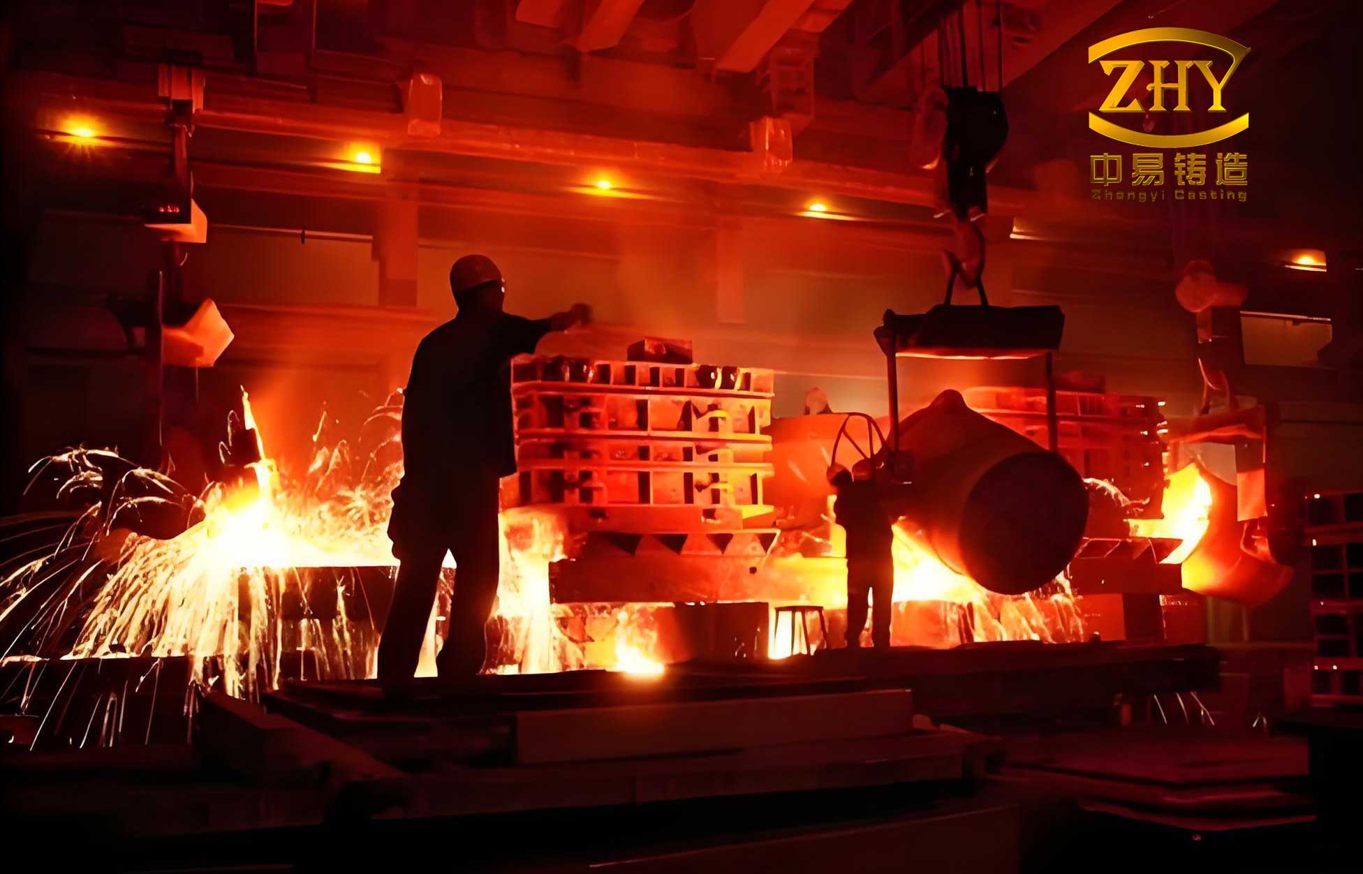
Process difficulties of the ductile iron castings. The high oil pressure injection molding machine template is a critical component of the clamping hydraulic system. Its structure is complex, and the service conditions are severe. The ductile iron castings must exhibit high mechanical properties and must not contain cracks, cold shuts, shrinkage cavities, porosity, or slag inclusions. Moreover, the castings must not leak oil under high pressure. Because of these stringent requirements, most injection molding machine manufacturers currently use forged steel components. However, we aimed to replace forged steel with ductile iron castings by overcoming the following difficulties:
| Challenge | Requirement | Consequence if not met |
|---|---|---|
| Eight cast holes used directly as oil cylinder holes | No shrinkage cavity or porosity; no oil leakage | Oil leakage, pressure loss, and component failure |
| Two layers of Φ30 mm oil channels in a 365 mm thick section | No shrinkage cavity or porosity; no leakage | High-pressure oil passage failure |
| Inner surface of oil cylinder holes | Surface roughness Ra 0.4–0.8 μm | Poor sealing and excessive wear |
| Oil pressure test | 20 MPa without seepage or leakage | Safety hazard and rejection |
| Heavy section | Uniform solidification and no thermal gradient defects | Shrinkage porosity, graphite degeneration, and low mechanical properties |
We recognized that the heavy section of 365 mm would cool slowly, leading to a low cooling rate, coarse graphite, and a high risk of shrinkage porosity. The carbon equivalent must be carefully controlled to promote graphitization and self-feeding. In addition, the presence of oil channels and cylinder holes makes the local thermal mass highly non-uniform. Therefore, we needed a casting process that could simultaneously ensure filling stability, directional solidification, and adequate feeding of the hot spots.
Casting process design. We selected the parting plane according to the principles of placing high-quality regions in the lower part of the mold, keeping the entire or most of the casting in one flask, and minimizing the number of parting planes. For this template, we placed the working face of the template at the bottom. This arrangement allowed the most critical surfaces to benefit from higher metal pressure and better feeding during solidification. The bottom pouring system was designed to achieve smooth and dispersed filling, to prevent turbulence, and to act as a slag trap. We used a dispersed ingate system with simultaneous solidification technology. A filter was placed at the junction between the runner and the ingates. Multiple ingates were used to reduce the number of inclusions in the metal matrix and to improve the mechanical properties of the ductile iron castings. The sprue and ingates were made of ceramic tubes to reduce sand erosion defects.
The gating system dimensions were determined based on the pouring weight and the required filling time. The sprue was a single ceramic tube with an inner diameter of Φ100 mm. The runner consisted of two trapezoidal channels with a cross-section of 60/70 (height 80 mm). The filter placement area was enlarged to provide a buffering effect. The ingates were eight ceramic tubes with an inner diameter of Φ40 mm. The total pouring time was simulated and verified to be 119 s. We also placed vents at locations where slag accumulation or gas entrapment was most likely to occur. These vents helped to discharge slag and gas from the mold cavity and guided the flow direction of the molten iron.
| Gating component | Material | Dimension | Quantity |
|---|---|---|---|
| Sprue | Ceramic tube | Inner diameter Φ100 mm | 1 |
| Runner | Trapezoidal channel | 60/70, height 80 mm | 2 |
| Ingate | Ceramic tube | Inner diameter Φ40 mm | 8 |
| Filter | Ceramic foam | Placed at runner–ingate junction | Multiple |
| Vent | Sand or ceramic | At high points and gas traps | Multiple |
To enhance the feeding of liquid shrinkage, we placed two rows of necked feeder heads at the highest points of the upper surface of the casting. Each feeder head had a diameter of Φ100 mm and a height of 600 mm. The neck height was at least 400 mm to facilitate feeding during liquid contraction. The feeder heads were designed to supply liquid metal to the hot spots and to compensate for the volume contraction of the ductile iron castings. We also calculated the feeding distance and the required feeder volume using the following relationships:
$$V_f = \beta \cdot V_c \cdot \left(1 + \frac{T_f – T_p}{T_p – T_m}\right)$$
where \(V_f\) is the feeder volume, \(\beta\) is the volumetric contraction coefficient, \(V_c\) is the casting volume, \(T_f\) is the feeder temperature, \(T_p\) is the pouring temperature, and \(T_m\) is the mold temperature. For ductile iron, \(\beta\) typically ranges from 0.03 to 0.06. We used a value of 0.045 for our calculation. The total feeder volume was approximately 2.4% of the casting volume, which was sufficient to compensate for liquid shrinkage and to promote self-feeding.
Cooling system design. The purpose of chills is to accelerate the cooling of hot spots and to prevent shrinkage porosity and cavity defects. Based on the structural analysis of the product, we used a large number of chills arranged as shown in our layout. The chills were made of graphite and cast iron, and they were placed on the thick section surfaces and around the oil channels. The chill layout increased the cooling rate of the heavy section and eliminated hot spots. We also used internal chills in the form of high-chromium steel rods for the deepest hot spots. The cooling rate \(R\) was estimated by:
$$R = \frac{\Delta T}{\Delta t} = \frac{T_p – T_s}{t_s}$$
where \(T_p\) is the pouring temperature, \(T_s\) is the solidus temperature, and \(t_s\) is the local solidification time. For the 365 mm section, the local solidification time without chills was approximately 4.5 h. With the chill arrangement, we reduced the local solidification time to approximately 2.8 h, which refined the graphite and improved the mechanical properties of the ductile iron castings.
| Location | Chill type | Size | Quantity | Purpose |
|---|---|---|---|---|
| Bottom surface | Graphite chill | 100 mm × 100 mm × 50 mm | 24 | Accelerate cooling of the working face |
| Side walls | Cast iron chill | 80 mm × 80 mm × 40 mm | 16 | Reduce thermal gradient |
| Around oil channels | Graphite chill | 50 mm × 50 mm × 30 mm | 32 | Prevent local shrinkage |
| Deep hot spots | High-chromium steel internal chill | Φ20 mm × 150 mm | 12 | Eliminate isolated liquid pools |
CAE simulation. Computer simulation technology provides guidance for the rational design of casting processes. We used ProCAST software to dynamically simulate the temperature field, velocity field, pressure field, and quality defects during the mold filling and solidification processes of the ductile iron castings. This simulation ensured the optimization of the casting process. The simulation parameters are summarized in the following table.
| Parameter | Value |
|---|---|
| Simulation software | ProCAST |
| Mesh size | 5 mm on critical surfaces, 10 mm in bulk |
| Initial mold temperature | 25 °C |
| Pouring temperature | 1,295 °C |
| Interface heat transfer coefficient | 1,000 W/(m²·K) for metal–mold |
| Cooling condition | Air cooling with chills |
| Simulated filling time | 119 s |
| Simulated solidification time | 4.5 h without chills; 2.8 h with chills |
The temperature field distribution during the filling process showed that the molten metal flowed smoothly and steadily. The temperature distribution throughout the casting was relatively uniform, and there was no region with excessively low temperature. The filling time was 119 s, which matched our design. The solid fraction distribution during solidification indicated that the last solidified regions were located away from the oil channels and oil cylinder holes. The shrinkage porosity and cavity prediction showed that potential defects were confined to the feeder heads and the upper surface, far from the critical oil passages. Therefore, we concluded that the gating system, feeder heads, and chill design were reasonable and effective for these ductile iron castings.
We also evaluated the filling velocity and pressure distribution. The maximum filling velocity was 0.85 m/s, which was below the critical velocity for turbulence in ductile iron. The pressure at the ingates was sufficient to fill the mold completely without cold shuts. The simulation results were consistent with the experimental observations. The following equations were used to assess the filling behavior:
$$Re = \frac{\rho v D}{\mu}$$
where \(Re\) is the Reynolds number, \(\rho\) is the density of liquid iron, \(v\) is the flow velocity, \(D\) is the hydraulic diameter, and \(\mu\) is the dynamic viscosity. For our filling conditions, \(Re\) was approximately 12,000, which is in the transitional regime. However, the dispersed ingates and the filter reduced turbulence and ensured laminar-like flow in the critical sections. We also calculated the modulus \(M\) of the casting and the feeder:
$$M = \frac{V}{A}$$
where \(V\) is the volume and \(A\) is the surface area. The modulus of the 365 mm section was 182 mm, while the modulus of the feeder head was 210 mm. The feeder modulus was 1.15 times the casting modulus, which satisfied the feeding criterion \(M_f \geq 1.2 M_c\) for ductile iron. This ensured that the feeder would solidify last and supply liquid metal to the casting.
Melt preparation and treatment. The production of large, heavy-section ductile iron castings requires strict control of chemical composition. We carefully controlled the carbon, silicon, and manganese contents, and we minimized phosphorus and sulfur. The raw materials were weighed in the following proportions: 40% pig iron, 40% steel scrap, and 20% returned scrap. The carburizer addition was 1.35% of the total weight of pig iron, steel scrap, and returned scrap. All raw materials were charged into the melting furnace, and the carburizer was added once during charging. After the charge was completely melted, FeSi75 ferrosilicon was added at 1.4% of the total weight to obtain the base iron. The base iron was further heated to 1,460 °C. The chemical composition of the base iron was: 3.60% C, 1.78% Si, 0.25% Mn, 0.021% P, 0.019% S, and the balance Fe.
| Element | Base iron (wt.%) | Treated iron (wt.%) | Target range (wt.%) |
|---|---|---|---|
| C | 3.60 | 3.42 | 3.40–3.60 |
| Si | 1.78 | 2.77 | 2.60–2.90 |
| Mn | 0.25 | 0.25 | 0.20–0.30 |
| P | 0.021 | 0.021 | ≤0.025 |
| S | 0.019 | 0.0098 | ≤0.012 |
| Mg | — | 0.035 | 0.030–0.045 |
| RE | — | 0.0085 | 0.005–0.015 |
| Sb | — | 0.0056 | 0.004–0.008 |
| CE | 4.19 | 4.34 | 4.25–4.45 |
The carbon equivalent \(CE\) was calculated as:
$$CE = C + \frac{Si}{3} + \frac{P}{3}$$
For the base iron, \(CE = 3.60 + 1.78/3 + 0.021/3 = 4.19\). For the treated iron, \(CE = 3.42 + 2.77/3 + 0.021/3 = 4.34\). This value is within the optimal range for heavy-section ductile iron castings, promoting graphitization and reducing shrinkage porosity. We intentionally kept the silicon content between 2.60% and 2.90% to avoid excessive ferrite and to maintain the strength of the ductile iron castings.
Spheroidization and inoculation. We used the sandwich method for spheroidization. In the spheroidizing pocket on one side of the treatment ladle, we first added the spheroidizing agent and compacted it. Then we added 3–8 mm inoculant and 1–5 mm preconditioner and compacted them. Finally, we added 0.006% pure antimony by weight of the base iron. The spheroidizing agent addition was 1.1% of the base iron weight. The spheroidizing agent was a mixture of 70% light rare earth magnesium alloy and 30% yttrium-based heavy rare earth magnesium alloy. The magnesium boil reaction lasted for 105 s. The compositions of the two alloys are given in the following table.
| Alloy | Mg (%) | RE (%) | Si (%) | Ca (%) | Ba (%) | Al (%) | MgO (%) | Fe (%) |
|---|---|---|---|---|---|---|---|---|
| Light rare earth magnesium alloy | 5.9 | 0.49 | 44.8 | 0.98 | 2.5 | 0.49 | 0.37 | Balance |
| Yttrium-based heavy rare earth magnesium alloy | 6.0 | 0.9 | 43.5 | 2.2 | — | 0.55 | 0.35 | Balance |
The inoculant addition was 0.70% of the base iron weight. The inoculant was a silicon–barium inoculant with the following composition: 72% Si, 1.0% Ca, 2.0% Ba, 0.70% Al, 0.015% S, and the balance Fe. The preconditioner addition was 0.20% of the base iron weight. The preconditioner was a high-barium treatment agent with the following composition: 62% Si, 0.8% Ca, 10.5% Ba, 0.65% Al, and the balance Fe. The treated iron composition was: 3.42% C, 2.77% Si, 0.25% Mn, 0.021% P, 0.0098% S, 0.035% Mg, 0.0085% RE, 0.0056% Sb, \(CE = 4.34\), and the balance Fe.
The yttrium-based heavy rare earth alloy was used to prolong the spheroidizing effect and to prevent magnesium fade, which is critical for large, heavy-section ductile iron castings. The light rare earth alloy provided rapid spheroidization, while the heavy rare earth alloy maintained the spheroidizing effect during the long solidification time. The antimony addition refined the graphite and increased the nodule count. The silicon–barium inoculant and the high-barium preconditioner provided heterogeneous nucleation sites and improved the nodularity. The following equation was used to estimate the nodule count \(N\):
$$N = N_0 + k \cdot \frac{1}{R}$$
where \(N_0\) is the base nodule count, \(k\) is a constant, and \(R\) is the cooling rate. By increasing the cooling rate with chills and adding potent inoculants, we achieved a high nodule count and a uniform distribution of graphite spheres in the ductile iron castings.
Pouring and final treatment. After the spheroidization and inoculation, the iron was transferred to the pouring site. We skimmed the slag again, and then we performed floating silicon inoculation on the surface of the iron. The inoculant addition for floating silicon inoculation was 0.08% of the total base iron weight. After this treatment, the iron was poured entirely into the pouring ladle and allowed to stand for 5 min. When the temperature dropped to 1,295 °C, we opened the stopper and poured. This pouring temperature was selected to ensure complete filling of the thin sections and oil channels while minimizing the risk of shrinkage porosity in the heavy section. The pouring temperature was controlled within ±10 °C. The pouring time was 119 s, which matched the simulation. The mold was a high-stiffness sand mold with a high packing density to resist the metallostatic pressure and to ensure dimensional accuracy.
Implementation results. Based on the CAE analysis, we strictly controlled the iron composition, strengthened the spheroidization and inoculation, and used a high-stiffness mold. The produced ductile iron castings and the machined template were inspected. The ultrasonic testing results met the level 1 requirements of EN 12680-3:2011. The magnetic particle testing results met the level 2 requirements of EN 13697:2023. The cast-on test blocks were D-type test blocks according to GB/T 1348-2019, with dimensions 70 mm × 105 mm × 200 mm. The mechanical properties and metallographic structures are shown in the following tables.
| Property | Customer requirement | Measured value |
|---|---|---|
| Tensile strength (MPa) | ≥390 | 421 |
| Yield strength (MPa) | ≥260 | 365 |
| Elongation (%) | ≥8.0 | 20 |
| Hardness (HBW) | 130–170 | 149 |
| Microstructural feature | Customer requirement | Measured value |
|---|---|---|
| Nodularity (%) | ≥90 | 95 |
| Graphite size grade | 5–8 | 6 |
| Graphite nodule size (mm) | 0.015–0.06 | 0.03–0.06 |
The graphite spheres were round and uniformly distributed. The nodularity, graphite grade, and mechanical properties all met the technical requirements. After machining, the oil cylinder holes of the ductile iron castings showed no casting defects, and the surface roughness reached Ra 0.4–0.8 μm. During the 20 MPa oil pressure test, there was no seepage or leakage. The successful production of these ductile iron castings confirmed that our process design was effective.
Discussion. The key to producing large, heavy-section ductile iron castings for high oil pressure injection molding machine templates is to simultaneously control solidification defects and graphite morphology. The heavy section of 365 mm leads to a low cooling rate, which promotes graphite degeneration, graphite floating, and shrinkage porosity. We addressed these issues through several complementary strategies. First, we designed a bottom gating system with dispersed ingates and a filter to ensure smooth filling and to reduce inclusions. Second, we placed two rows of necked feeder heads at the highest points and used a large number of chills to accelerate cooling and to eliminate hot spots. Third, we carefully balanced the carbon equivalent and the silicon content to promote graphitization and self-feeding. Fourth, we used a combined spheroidizing agent of light rare earth and heavy rare earth magnesium alloys to maintain the spheroidizing effect during the long solidification time. Fifth, we added antimony to refine the graphite and to increase the nodule count. Sixth, we used a high-barium preconditioner and a silicon–barium inoculant to provide nucleation sites and to improve nodularity.
The CAE simulation was indispensable for optimizing the process. The filling simulation predicted a smooth flow with a filling time of 119 s. The solidification simulation predicted that the last solidified regions would be located in the feeder heads, away from the oil channels and oil cylinder holes. The shrinkage porosity prediction confirmed that no defects would occur in the critical regions. The simulation also helped us to optimize the chill layout and the feeder size. The modulus calculation and the feeding criterion \(M_f \geq 1.2 M_c\) were used to verify the feeder design. The thermal analysis and the cooling rate calculation guided the selection of the chill size and placement.
We also considered the effect of trace elements on the mechanical properties of the ductile iron castings. Phosphorus and sulfur were kept low to avoid embrittlement and to ensure good spheroidization. Manganese was controlled at 0.25% to avoid excessive pearlite and to maintain toughness. The antimony addition of 0.0056% was optimal for refining graphite without causing graphite degeneration. The rare earth content of 0.0085% was sufficient to neutralize sulfur and oxygen but not excessive to cause spheroidal graphite degeneration or dross formation. The magnesium content of 0.035% was within the optimal range for heavy-section ductile iron castings. The final microstructure consisted of a ferritic matrix with uniformly distributed graphite nodules, which provided the required combination of strength and ductility.
The mechanical properties exceeded the customer requirements. The tensile strength of 421 MPa, yield strength of 365 MPa, and elongation of 20% are excellent for QT450-10A ductile iron. The hardness of 149 HBW is within the specified range. The nodularity of 95% and the graphite size grade of 6 indicate a high-quality microstructure. The ultrasonic testing level 1 and magnetic particle testing level 2 confirm the internal and surface integrity of the ductile iron castings. The 20 MPa oil pressure test without leakage validates the pressure-tightness of the template.
Conclusions. We have successfully developed a casting process for large, heavy-section ductile iron castings used as high oil pressure injection molding machine templates. The following conclusions can be drawn:
1. We designed a bottom gating system with a single Φ100 mm sprue, two trapezoidal runners, eight Φ40 mm ceramic tube ingates, and a ceramic foam filter. The dispersed ingates ensured smooth filling and simultaneous solidification. The filling time was 119 s. We placed two rows of Φ100 mm × 600 mm necked feeder heads at the highest points and used a large number of graphite and cast iron chills to accelerate cooling and eliminate hot spots. The critical oil cylinder holes and oil channels were free of shrinkage cavity and porosity.
2. We strictly controlled the chemical composition of the iron. The base iron contained 3.60% C, 1.78% Si, 0.25% Mn, 0.021% P, and 0.019% S. The treated iron contained 3.42% C, 2.77% Si, 0.25% Mn, 0.021% P, 0.0098% S, 0.035% Mg, 0.0085% RE, and 0.0056% Sb. The carbon equivalent was 4.34. The low phosphorus and sulfur contents and the optimal silicon range promoted graphitization and self-feeding. The antimony addition refined the graphite and increased the nodule count.
3. We used a combined spheroidizing agent of 70% light rare earth magnesium alloy and 30% yttrium-based heavy rare earth magnesium alloy. The spheroidizing agent addition was 1.1% of the base iron weight. The magnesium boil reaction lasted for 105 s. We used a silicon–barium inoculant at 0.70% and a high-barium preconditioner at 0.20%. We also performed floating silicon inoculation at 0.08%. This comprehensive melt treatment ensured a high nodularity and a uniform graphite distribution in the ductile iron castings.
4. The produced ductile iron castings met the customer requirements. The ultrasonic testing results met EN 12680-3:2011 level 1. The magnetic particle testing results met EN 13697:2023 level 2. The cast-on test blocks exhibited a tensile strength of 421 MPa, a yield strength of 365 MPa, an elongation of 20%, and a hardness of 149 HBW. The nodularity was 95%, the graphite size grade was 6, and the graphite nodule size was 0.03–0.06 mm. The machined oil cylinder holes achieved a surface roughness of Ra 0.4–0.8 μm and passed the 20 MPa oil pressure test without leakage.
5. The combination of CAE simulation, precise melt treatment, optimized gating and feeding, and effective cooling system design provides a reliable route for manufacturing large, heavy-section ductile iron castings for high-pressure hydraulic applications. The process can be extended to similar heavy-section ductile iron castings with strict pressure-tightness and mechanical property requirements.
In summary, our work demonstrates that with careful process design and strict quality control, ductile iron castings can replace forged steel in high oil pressure injection molding machine templates. The ductile iron castings offer advantages in terms of cost, machinability, and design flexibility while meeting the demanding performance requirements. The key success factors are the control of solidification defects, the refinement of graphite morphology, and the assurance of pressure-tightness. These findings contribute to the broader application of ductile iron castings in heavy-section hydraulic components.