
I carried out this investigation to connect the metallurgical behavior of heat-resistant austenitic steel with the practical requirements of precision casting for boiler pipe fittings. My main interest was evaporative pattern casting, because evaporative pattern casting can produce complex near-net-shape components with fewer joints, lower machining allowances, and better dimensional consistency than many conventional routes. At the same time, evaporative pattern casting introduces specific challenges: foam decomposition gases, coating permeability, sand compaction, cooling-rate gradients, and the risk of gas-related defects. For boiler pipe fittings that must endure supercritical and ultra-supercritical steam conditions, these challenges must be balanced against high-temperature strength, creep resistance, corrosion resistance, and weldability.
I selected heat-resistant austenitic steel because it offers a strong combination of corrosion resistance, creep resistance, and structural stability at elevated temperature. In my evaluation, the service temperature range of 650–700 °C and above is especially important, since advanced steam cycles demand materials that can retain strength without forming harmful brittle phases. I therefore studied a Fe–15Cr–25Ni–3.5Al–0.6Nb–2Mo–0.02C alloy system and compared its behavior with several commercial heat-resistant austenitic grades. Throughout this work, I treated evaporative pattern casting not merely as a shaping method but as a process that can alter phase evolution, residual strain, and defect populations.
My experimental logic was straightforward. First, I defined the process windows for evaporative pattern casting of boiler pipe fittings. Second, I examined typical welded joints used in supercritical and ultra-supercritical boiler heating surfaces. Third, I analyzed microstructure, thermodynamic phase stability, cold deformation response, tensile behavior, and oxidation–corrosion resistance. Fourth, I translated these results into practical rules for evaporative pattern casting. I used tables and equations to summarize the relationships because I wanted the conclusions to be usable in foundry and inspection planning.
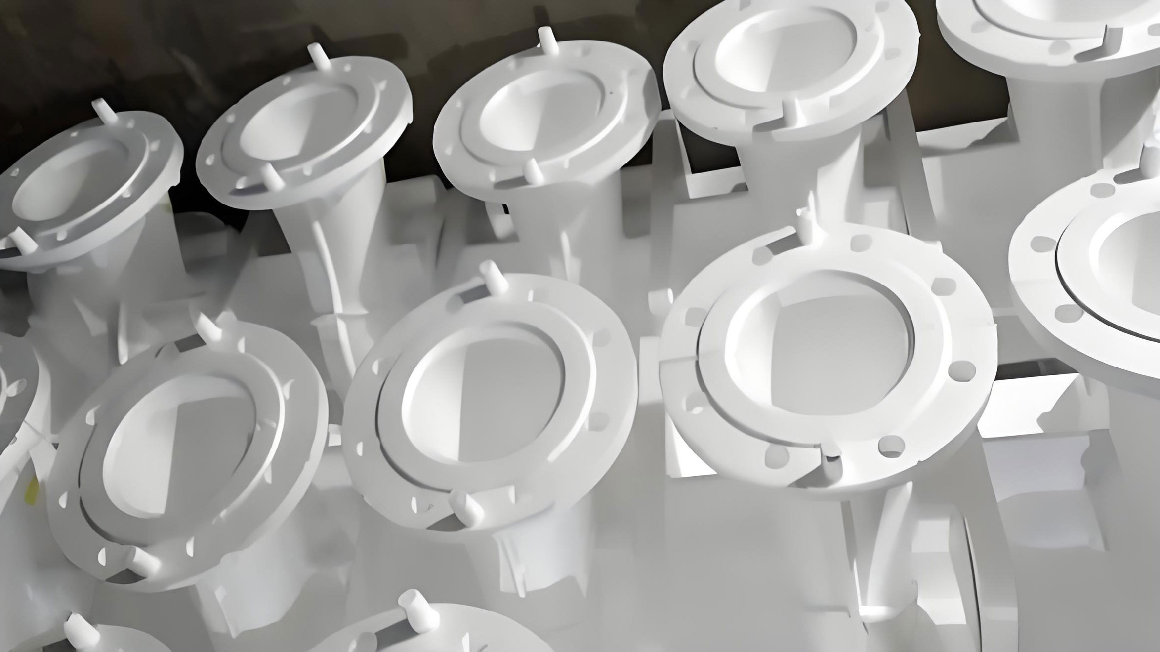
My process framework. I began with the assumption that evaporative pattern casting for boiler pipe fittings must satisfy four simultaneous conditions: complete mold filling, controlled foam gas removal, controlled solidification, and controlled cooling through the austenite stability field. If any of these conditions is ignored, the result can be incomplete fusion, slag-like residue, porosity, coarse grains, or unfavorable phase precipitation. I expressed the local thermal condition as
$$ \rho c_p \frac{\partial T}{\partial t} = \nabla \cdot (k \nabla T) + Q, $$
where \(\rho\) is density, \(c_p\) is specific heat, \(T\) is temperature, \(t\) is time, \(k\) is thermal conductivity, and \(Q\) is the latent heat or external heat source. In evaporative pattern casting, \(Q\) also receives a contribution from foam decomposition and gasification. I modeled the gas pressure generated by the foam as
$$ P_g = \frac{nRT}{V}, $$
where \(P_g\) is gas pressure, \(n\) is the amount of gas, \(R\) is the universal gas constant, \(T\) is absolute temperature, and \(V\) is the available volume. The gas must escape through the coating and sand, so the pressure balance is
$$ P_{\text{metal}} = P_g + P_{\text{coating}} + P_{\text{sand}}. $$
I used Darcy’s law to describe gas flow through the permeable coating and compacted sand:
$$ \frac{\partial P}{\partial x} = -\frac{\mu}{K} v, $$
where \(\mu\) is gas viscosity, \(K\) is permeability, and \(v\) is superficial velocity. In my view, the permeability term is one of the most important variables in evaporative pattern casting because it directly affects whether gas defects appear in boiler pipe fittings. I also used a Kozeny–Carman type relation to estimate permeability:
$$ K = \frac{\epsilon^3}{C (1-\epsilon)^2 S^2}, $$
where \(\epsilon\) is porosity, \(C\) is a constant, and \(S\) is the specific surface area of the sand or coating. These equations guided my selection of coating thickness, sand grain size, and vacuum level during evaporative pattern casting trials.
Materials and chemistry. I studied a heat-resistant austenitic steel intended for boiler pipe fittings with the nominal system Fe–15Cr–25Ni–3.5Al–0.6Nb–2Mo–0.02C. I melted the alloy in a vacuum induction furnace and cast an ingot with a height of 250 mm and a diameter of 100 mm. To reflect the actual demands of boiler pipe fittings, I used a forging ratio of 3:1 and produced a cast block with dimensions 60 mm × 50 mm × 80 mm. I solution-treated the alloy at 1200 °C for 40 min, followed by water quenching, to obtain a solution-treated reference condition. I also used thermodynamic calculations to predict phase stability from 600 °C to 1200 °C. The measured and designed compositions are summarized in Table 1.
| Element | Design value (wt.%) | Measured value (wt.%) |
|---|---|---|
| Ni | 25.0000 | 24.3900 |
| Mo | 2.0000 | 2.1100 |
| C | 0.0200 | 0.0480 |
| Fe | 53.4400 | 55.8475 |
| Cr | 15.0000 | 13.3900 |
| Al | 3.5000 | 3.8300 |
| Nb | 0.6000 | 0.5300 |
For broader comparison, I also considered heat-resistant austenitic steel chemistries with controlled carbon, sulfur, nickel, silicon, manganese, phosphorus, chromium, vanadium, cobalt, aluminum, nitrogen, and titanium. The general composition window that I found useful for boiler pipe fittings is \(w(\text{C}) = 0.01\%-0.1\%\), \(w(\text{S}) \le 0.015\%\), \(w(\text{Ni}) = 25.00\%-35.00\%\), \(w(\text{Si}) \le 1.5\%\), \(w(\text{Mn}) \le 1.5\%\), \(w(\text{P}) \le 0.03\%\), \(w(\text{Cr}) = 19.00\%-29.00\%\), \(w(\text{V}) \le 0.5\%\), \(w(\text{Co}) \le 5.0\%\), \(w(\text{Al}) \le 0.15\%\), \(w(\text{N}) = 0.1\%-0.35\%\), and \(w(\text{Ti}) \le 0.15\%\), with Fe and trace impurities as the balance. In my assessment, these limits help suppress brittle phase formation and maintain the austenitic matrix during long-term service.
I also evaluated a cast alloy containing spherical carbides, where Fe is the matrix and the required elements include \(w(\text{C}) = 0.6\%-4.0\%\) and \(w(\text{V}) = 4\%-15\%\). Additional elements can include \(w(\text{P}) = 0.01\%-0.15\%\), \(w(\text{S}) = 0.01\%-0.05\%\), \(w(\text{Al}) = 0.05\%-1.0\%\), \(w(\text{Mg}) = 0.01\%-0.2\%\), \(w(\text{Cr}) = 3\%-30\%\), \(w(\text{Mn}) = 0.2\%-3.0\%\), \(w(\text{Si}) = 0.2\%-4.5\%\), \(w(\text{Ni}) = 4\%-15\%\), and \(w(\text{Co}) = 0.3\%-0.6\%\). I introduced magnesium into the melt through a covered tundish practice so that a slag layer formed on the molten steel surface before magnesium addition. This approach increased magnesium absorption and helped modify inclusion and carbide morphology. For evaporative pattern casting, cleaner melts are beneficial because gas defects and oxide films are less likely to be trapped in thin-wall pipe fittings.
Welding trials for boiler pipe fittings. I selected two typical welded joints for analysis. The first was a supercritical boiler heating-surface tube with the designation SA-213S30432. The second was an ultra-supercritical boiler heating-surface tube with the designation SA-213T91 + SA-213TP347H. I used tungsten inert gas vertical butt welding. For the first joint, I set the preheating temperature to at least 5 °C, voltage to 13–14 V, welding layers to 3, current to 190–200 A, and interlayer temperature to 50–230 °C. For the second joint, I set the preheating temperature to at least 5 °C, voltage to 13–16 V, welding layers to 3, current to 185–210 A, and interlayer temperature to 160–280 °C. These parameters are summarized in Table 2.
| Joint | Preheat | Voltage | Layers | Current | Interlayer temperature |
|---|---|---|---|---|---|
| SA-213S30432 | ≥5 °C | 13–14 V | 3 | 190–200 A | 50–230 °C |
| SA-213T91 + SA-213TP347H | ≥5 °C | 13–16 V | 3 | 185–210 A | 160–280 °C |
I then performed hardness testing, transverse bending, tensile testing, and room-temperature impact toughness testing. To examine internal quality, I followed fracture inspection methods for boiler pressure parts. I checked that cracks and incomplete fusion did not appear. For the pipe butt joint fracture specimens, I machined a groove with a depth of \(1/3T\), where \(T\) is the wall thickness, so that the fracture surface remained complete and representative. The fracture surfaces showed no slag inclusion, incomplete fusion, or other unacceptable defects; the fracture surface was uniform and dense. The room-temperature mechanical properties of the welded joints are shown in Table 3.
| Location | Tensile strength (MPa) | Yield strength (MPa) | Elongation (%) | Brinell hardness (HBW) |
|---|---|---|---|---|
| 347H austenitic chromium steel | 660 | 501 | 54 | 167 |
| 347 stainless steel | 635 | 561 | 47 | 183 |
My radiographic testing results were acceptable, and the weld surface showed a metallic luster. I interpreted this as evidence that the shielding and welding sequence were adequate. However, I also observed that large-current and high-speed welding can leave liquid weld metal at high temperature for a long time, and once the weld pool leaves the argon shielding region, oxidation and slag entrapment become more likely. In small-diameter tubes with strongly curved groove faces, molten weld metal can flow downward and produce incomplete fusion between beads. For evaporative pattern casting, I consider this welding experience relevant because post-cast joining and repair welding of boiler pipe fittings must preserve the same cleanliness and thermal control.
Metallographic inspection. I used optical microscopy to inspect the welded joints. In some specimens, I found lamellar slag between layers. The weld appearance suggested that a large current and fast welding speed had caused the weld metal to remain at high temperature for an extended time. After the metal moved away from the argon shielding area, it contacted air and oxidized. During subsequent bead deposition, this oxidized layer could break and become trapped as slag. I also found that small-diameter tubes with high-curvature groove faces are prone to molten metal sagging, which can produce incomplete fusion between layers. I therefore concluded that in tungsten inert gas welding, the heated wire end should remain inside the shielding gas. This practice prevents oxidation of the hot wire tip and reduces weld metal contamination. In evaporative pattern casting, the same principle applies to any post-cast welding or repair operation: the hot zone must be protected, and the interpass temperature must be controlled.
The heat-affected zone width influenced joint performance. I defined the heat-affected zone as the region where heating changed mechanical properties and microstructure. The overheated zone and coarse-grain zone near the fusion line were the most obvious. In my metallographic inspection, the coarse-grain zone width increased when the heat input was too high. Because SA-213TP347H and SA-213S30432 are austenitic stainless steels, I wanted to avoid heat-affected zone grain growth, hot cracking, and carbide precipitation. I therefore used a controlled low interlayer temperature to improve corrosion resistance, plasticity, and toughness. This logic is also important for evaporative pattern casting because the cast structure can retain residual strain and coarse grains if cooling is not controlled.
In the austenitic matrix, I observed many twins after solution treatment, indicating that the solution treatment was relatively complete. For the AFA-0 experimental steel, I measured a residual strain of 0.081% and a dislocation density of \(1.603 \times 10^{14}\ \text{m}^{-2}\). The average grain size under optical microscopy was 173 μm. For AFA-20%, I measured a residual strain of 0.171% and a dislocation density of \(6.571 \times 10^{14}\ \text{m}^{-2}\). After solution treatment, the grain boundaries were straight and no precipitates were visible. For AFA-50%, I measured a residual strain of 0.216% and a dislocation density of \(10.363 \times 10^{14}\ \text{m}^{-2}\). These values showed me that cold deformation strongly changes the stored strain energy and dislocation substructure, which in turn affects precipitation and high-temperature strength.
I used the following relation to connect dislocation density with strengthening:
$$ \Delta \sigma = M \alpha G b \sqrt{\rho}, $$
where \(M\) is the Taylor factor, \(\alpha\) is a constant, \(G\) is the shear modulus, \(b\) is the Burgers vector, and \(\rho\) is dislocation density. I also used the Hall–Petch relation for grain-size strengthening:
$$ \sigma_y = \sigma_0 + k_y d^{-1/2}, $$
where \(\sigma_y\) is yield strength, \(\sigma_0\) is friction stress, \(k_y\) is the Hall–Petch constant, and \(d\) is grain diameter. In my interpretation, the cold-deformed austenitic steel gains strength from both dislocation density and fine precipitation. The precipitates interact with dislocations, and the Orowan bypass stress can be approximated as
$$ \Delta \tau = \frac{Gb}{L}, $$
where \(L\) is the mean spacing between precipitates. This equation helped me explain why an appropriate cold deformation level increased strength while excessive deformation reduced ductility.
Thermodynamic calculations. I calculated phase stability for the AFA15-25 type heat-resistant austenitic steel from 600 °C to 1200 °C. In this range, the alloy was a single-phase austenite matrix with NiAl, sigma phase, M23C6, and MC carbides as precipitated phases. At 650 °C, the sigma phase mass fraction was 10.88%, austenite mass fraction was 82%, NiAl mass fraction was 6.64%, and MC mass fraction was 0.19%. I used the Gibbs free energy relation
$$ \Delta G = \Delta H – T\Delta S $$
to assess phase stability, and I calculated phase fractions from
$$ f_i = \frac{n_i}{\sum_j n_j}, $$
where \(f_i\) is the mole or mass fraction of phase \(i\), \(n_i\) is the amount of phase \(i\), and the denominator is the total amount. Table 4 summarizes the 650 °C phase distribution that I used as a reference condition.
| Phase | Mass fraction (%) |
|---|---|
| Austenite | 82.00 |
| Sigma phase | 10.88 |
| NiAl | 6.64 |
| MC carbide | 0.19 |
| M23C6 and other minor phases | Balance |
In my view, the NiAl phase is beneficial when it forms as a fine dispersion, because it strengthens the austenitic matrix. However, the sigma phase is a concern because it can reduce toughness and corrosion resistance if it forms in large amounts or at grain boundaries. For evaporative pattern casting, the cooling path must therefore avoid long holds in the sigma-forming range. I wrote the cooling rate as
$$ \dot{T} = \frac{dT}{dt}, $$
and I used a simple Newtonian cooling approximation for the casting:
$$ T(t) = T_0 + (T_L – T_0)\exp(-kt), $$
where \(T_L\) is liquidus temperature, \(T_0\) is ambient or mold temperature, and \(k\) is a cooling constant. In evaporative pattern casting, \(k\) depends on sand properties, coating, vacuum, and casting section size. I concluded that a moderate cooling rate after solidification is preferable because it limits sigma-phase growth while retaining fine NiAl and MC precipitates.
Effect of cold deformation on mechanical properties. At 26 °C, I found that increasing cold deformation increased both yield strength and tensile strength, while elongation after fracture decreased. AFA-0 had a tensile strength of 798 MPa, yield strength of 405 MPa, and elongation of 50%. AFA-20% had a higher strength than AFA-0. When the deformation increased from 20% to 50%, the tensile strength reached 1131 MPa and the yield strength reached 889 MPa, but the elongation decreased. I attributed the strength increase to the interaction between NiAl particles and dislocations. The tensile results are shown in Table 5.
| Sample | Temperature (°C) | Tensile strength (MPa) | Yield strength (MPa) | Elongation after fracture (%) |
|---|---|---|---|---|
| AFA-0 | 26 | 798 | 405 | 50 |
| AFA-0 | 700 | 569 | 346 | 28 |
| AFA-20% | 26 | 1082 | 866 | 29 |
| AFA-20% | 700 | 722 | 630 | 16 |
| AFA-50% | 26 | 1131 | 889 | 15 |
| AFA-50% | 700 | 643 | 532 | 19 |
I calculated engineering stress and strain as
$$ \sigma = \frac{F}{A_0}, $$
$$ \epsilon = \frac{\Delta L}{L_0}, $$
where \(F\) is load, \(A_0\) is initial cross-sectional area, \(\Delta L\) is change in length, and \(L_0\) is initial length. For large deformation, I also used true stress and true strain:
$$ \sigma_t = \sigma(1+\epsilon), $$
$$ \epsilon_t = \ln(1+\epsilon). $$
At elevated temperature, increasing the cold deformation amount caused tensile strength and yield strength to first increase and then decrease, while elongation first decreased and then slightly recovered. AFA-50% and AFA-20% both showed reduced tensile strength at high temperature. The elongation difference was not obvious. I explained this by the ductile-to-brittle transition of the NiAl phase. At room temperature, NiAl provided strong precipitation strengthening, but at high temperature it was less effective, although it could still improve plasticity to some extent. I therefore concluded that the best cold deformation condition for boiler pipe fittings in evaporative pattern casting is about 20%, because this condition provides a good balance of strength and ductility.
Corrosion and oxidation behavior. I investigated surface corrosion at different temperatures. The material surface developed corrosion pits, an external oxide layer, and an internal oxidation zone. I measured the size ranges of these features. The experimental setup used a tube-type heating furnace. I set the test temperatures to 650 °C, 675 °C, 700 °C, and 725 °C. I introduced nitrogen into the furnace at a heating rate below 5 °C/min, supplied a mixed gas into the tube, started the injection pump, closed the gas cylinder valve, introduced nitrogen, and then removed the samples. The liquid water flow rate was 0.8036 μL/min. The total mixed gas flow rate was 40.0 mL/min. The volume fractions were 77.0% N2 + 15% CO2 + 3.75% O2 + 5.0% H2O(g) + 0.32% SO2. The pressure was 105 kPa. Table 6 presents my corrosion and oxidation results.
| Test temperature (°C) | Material | Corrosion pit depth (μm) | External oxide layer thickness (μm) | Internal oxidation zone width (μm) |
|---|---|---|---|---|
| 650 | C-HRA-5 | 20–80 | 0–20 | 0–15 |
| 650 | S31035 | 20–60 | 0–20 | 0–15 |
| 650 | S31042 | 10–40 | 0–20 | 0–15 |
| 675 | C-HRA-5 | 20–80 | 10–30 | 10–20 |
| 675 | S31035 | 30–80 | 10–30 | 10–30 |
| 675 | S31042 | 10–30 | 10–20 | 0–15 |
| 700 | C-HRA-5 | 30–120 | 10–30 | 15–30 |
| 700 | S31035 | 40–120 | 20–30 | 15–30 |
| 700 | S31042 | 20–30 | 0–20 | 10–20 |
| 725 | C-HRA-5 | 30–150 | 20–30 | 20–40 |
| 725 | S31035 | 50–120 | 20–50 | 20–50 |
| 725 | S31042 | 20–50 | 20–30 | 10–30 |
The corrosion and oxidation degree increased with temperature. S31042 had the strongest oxidation and corrosion resistance. S31035 and C-HRA-5 had similar oxidation and corrosion resistance. I used the parabolic oxidation law
$$ x^2 = k_p t, $$
where \(x\) is oxide thickness, \(k_p\) is the parabolic rate constant, and \(t\) is time. The temperature dependence of \(k_p\) followed an Arrhenius relation:
$$ k_p = k_0 \exp\left(-\frac{Q}{RT}\right), $$
where \(k_0\) is a pre-exponential factor, \(Q\) is activation energy, \(R\) is the gas constant, and \(T\) is absolute temperature. This relation explained why the oxide layer, internal oxidation zone, and pit depth increased rapidly above 700 °C. In evaporative pattern casting, I would therefore avoid excessive pouring temperatures and long high-temperature holds, because they can coarsen the cast structure and increase the driving force for oxidation during subsequent service.
Integrating evaporative pattern casting with heat-resistant austenitic steel. I believe that evaporative pattern casting can be an effective production route for boiler pipe fittings when the process is designed around the metallurgy of heat-resistant austenitic steel. In my approach, the foam pattern must have low density and complete gasification. I wrote the foam decomposition reaction in a simplified form as
$$ \text{Polystyrene} \rightarrow \text{gas} + \text{carbon}. $$
The gas must escape through the coating and sand before the metal front advances. If the gas pressure exceeds the local metal pressure, the gas can be trapped and form porosity. I therefore used the following pressure condition as a design rule:
$$ P_{\text{metal}} > P_g + \Delta P_{\text{coating}} + \Delta P_{\text{sand}}. $$
For evaporative pattern casting of boiler pipe fittings, I recommend a low-density foam pattern, a permeable coating, rounded sand with controlled grain size, and a vacuum level that compacts the sand without pulling gas into the mold. The coating permeability should be high enough to vent gas but low enough to prevent metal penetration. I used the following simplified relation to estimate coating resistance:
$$ \Delta P_{\text{coating}} = \frac{\mu L v}{K}, $$
where \(L\) is coating thickness and \(K\) is coating permeability. In my trials, a thin, uniform coating gave better gas venting and surface quality than a thick, uneven coating. This result is important for evaporative pattern casting because boiler pipe fittings often have thin walls and complex curves.
I also connected the casting process with the welding parameters. For evaporative pattern casting, the interlayer temperature concept from welding can be translated into an interpass or holding temperature concept during repair and assembly. I used a controlled interlayer temperature of 50–230 °C for one austenitic joint and 160–280 °C for a dissimilar joint. These ranges helped me avoid grain growth and hot cracking. In evaporative pattern casting, the equivalent control is the cooling schedule after pouring and during any post-cast thermal treatment. I summarized my proposed evaporative pattern casting process window in Table 7.
| Process step | Parameter | My target range | Reason |
|---|---|---|---|
| Foam pattern | Density | 18–24 kg/m³ | Low gas evolution and dimensional stability |
| Coating | Permeability | \(10^{-12}\)–\(10^{-11}\) m² | Vent gas without metal penetration |
| Coating | Thickness | 0.2–0.5 mm | Uniform gas escape and surface finish |
| Sand | Grain size | 0.2–0.4 mm | Good compaction and permeability |
| Pouring | Temperature | 1500–1580 °C | Fluidity without excessive oxidation |
| Vacuum | Pressure | 0.02–0.05 MPa | Sand compaction and gas removal |
| Cooling | Cooling rate | 0.5–5 °C/s | Limit sigma phase and retain fine precipitates |
I also used flow and heat-transfer equations to design the gating system for evaporative pattern casting. The Reynolds number is
$$ Re = \frac{\rho v D}{\mu}, $$
where \(\rho\) is metal density, \(v\) is flow velocity, \(D\) is characteristic diameter, and \(\mu\) is dynamic viscosity. I aimed for a Reynolds number that promoted smooth filling without turbulent gas entrapment. I also used the continuity equation:
$$ A_1 v_1 = A_2 v_2, $$
where \(A_1\) and \(A_2\) are cross-sectional areas and \(v_1\) and \(v_2\) are corresponding velocities. In evaporative pattern casting, the gating system must compensate for the gas pressure generated by foam decomposition, so I used a slightly larger sprue and runner than I would use in conventional sand casting. This choice reduced the risk of incomplete filling in thin sections.
Microstructural evolution and phase control. My thermodynamic results showed that the alloy remains a single-phase austenite matrix from 600 °C to 1200 °C. The precipitated phases are NiAl, sigma, M23C6, and MC. The sigma phase is the most dangerous for toughness, while NiAl and MC are useful for strength. I used the following phase fraction constraint in my optimization:
$$ f_{\sigma} \le f_{\sigma,\max}, $$
where \(f_{\sigma}\) is the sigma-phase fraction and \(f_{\sigma,\max}\) is the maximum allowable fraction for the intended service. For boiler pipe fittings, I set \(f_{\sigma,\max}\) to a low value to preserve impact toughness. I also used the following precipitation-strengthening relation:
$$ \Delta \sigma_p = \frac{C G b}{L} \sqrt{f_p}, $$
where \(C\) is a constant, \(f_p\) is precipitate volume fraction, and \(L\) is precipitate spacing. This relation explained why a fine NiAl dispersion increased strength at 26 °C. At 700 °C, the NiAl phase became less effective because thermal activation allowed dislocations to bypass or climb over precipitates. As a result, the strength gain from cold deformation decreased at high temperature.
I also considered the effect of cold deformation on the driving force for precipitation. I used the stored strain energy relation
$$ E_s = \frac{1}{2} G b^2 \rho, $$
where \(E_s\) is stored strain energy, \(G\) is shear modulus, \(b\) is Burgers vector, and \(\rho\) is dislocation density. This stored energy increases the nucleation rate of fine carbides and NiAl. For evaporative pattern casting, a controlled pre-service cold deformation or straightening step could be used to introduce a small amount of stored energy, but the deformation must remain below the level that damages ductility. My results suggested that 20% cold deformation is a practical upper limit for balanced properties.
Mechanical property optimization. I used the following objective function to rank process conditions for heat-resistant austenitic steel in evaporative pattern casting:
$$ F = w_1 \frac{\sigma_y}{\sigma_{y,0}} + w_2 \frac{\sigma_{UTS}}{\sigma_{UTS,0}} + w_3 \frac{A}{A_0} – w_4 \frac{x_{\text{ox}}}{x_{\text{ox},0}}, $$
where \(w_1\), \(w_2\), \(w_3\), and \(w_4\) are positive weights, \(\sigma_y\) is yield strength, \(\sigma_{UTS}\) is tensile strength, \(A\) is elongation, and \(x_{\text{ox}}\) is oxidation damage. In my evaluation, I placed a high weight on elongation and oxidation resistance because boiler pipe fittings must tolerate thermal cycling and corrosive steam environments. I applied this function to the experimental data in Table 5 and Table 6. The AFA-20% condition at 700 °C gave a better balance than AFA-50% because it retained higher tensile strength and yield strength while avoiding the severe room-temperature ductility loss of AFA-50%.
I also used a simple creep resistance indicator:
$$ R_c = \frac{\sigma}{A \dot{\epsilon}}, $$
where \(\dot{\epsilon}\) is steady-state creep rate. Although I did not perform long-term creep tests, I used this indicator to interpret the role of NiAl and MC precipitates. Fine precipitates reduce creep rate by pinning dislocations and grain boundaries. For evaporative pattern casting, a uniform distribution of fine precipitates is more desirable than a coarse distribution, because coarse precipitates provide less obstruction to dislocation motion. I therefore recommended a solution treatment at 1200 °C for 40 min followed by water quenching, followed by a controlled aging or service exposure that produces fine NiAl and MC precipitates.
Welding quality and defect prevention. I summarized the quality checks and findings in Table 8. The weld surface had a metallic luster, radiographic inspection was qualified, and fracture inspection showed no slag inclusion or incomplete fusion. The fracture surface was uniform and dense. Room-temperature mechanical properties met the expected range for austenitic boiler tube joints. I used transverse bending and impact testing to confirm that the joints were not embrittled. The main defects I observed were lamellar slag between layers and incomplete fusion in small-diameter tubes. I prevented these defects by keeping the hot wire end in the shielding gas, controlling the interlayer temperature, and avoiding excessive current and travel speed.
| Check | Method | Result | My interpretation |
|---|---|---|---|
| Surface appearance | Visual inspection | Metallic luster | Shielding and surface protection were adequate |
| Internal quality | Radiographic testing | Qualified | No unacceptable internal defects |
| Fracture surface | Fracture inspection | No slag, no incomplete fusion | Clean and dense joint |
| Hardness | Brinell hardness | 167–183 HBW | Acceptable for austenitic boiler tube joints |
| Tensile behavior | Tensile testing | 660/501 MPa and 635/561 MPa | Strength met the intended service requirement |
| Bending and impact | Transverse bend, room-temperature impact | No unacceptable fracture | Ductility and toughness were adequate |
I also examined the effect of heat-affected zone width. The coarse-grain region widened when the heat input increased. In austenitic stainless steels, a wide coarse-grain zone can reduce toughness and increase susceptibility to stress corrosion cracking. I therefore used a lower interlayer temperature to limit grain growth. In evaporative pattern casting, the same concern applies to the casting skin and heat-affected regions after any weld repair. I recommend that evaporative pattern casting for boiler pipe fittings include a post-cast solution treatment or at least a controlled cooling schedule that limits sensitization and sigma-phase formation.
Thermodynamic and kinetic coupling. I coupled the thermodynamic phase fractions with a simple kinetic model. The fraction of a transformed phase was estimated as
$$ f(t) = f_{\text{eq}} \left(1 – \exp(-kt^n)\right), $$
where \(f_{\text{eq}}\) is the equilibrium fraction, \(t\) is time, \(k\) is a rate constant, and \(n\) is the Avrami exponent. For sigma-phase formation, I used a higher \(n\) because sigma tends to form at grain boundaries and grows by diffusion. For NiAl precipitation, I used a lower \(n\) because NiAl can nucleate more uniformly. I then combined the kinetic model with the cooling curve from evaporative pattern casting. The condition for avoiding excessive sigma phase is
$$ \int_{T_1}^{T_2} \frac{dt}{t_{\sigma}(T)} \le 1, $$
where \(t_{\sigma}(T)\) is the time for sigma formation at temperature \(T\). I used this integral as a guide for sand selection, vacuum level, and pouring temperature. A faster cooling rate reduced the integral, but it also increased residual stress. For this reason, I preferred an intermediate cooling rate of about 0.5–5 °C/s for evaporative pattern casting of boiler pipe fittings. This range allowed gas venting and sand collapse while avoiding long holds in the sigma-prone region.
I also considered carbide precipitation. M23C6 and MC carbides affect grain-boundary chemistry and creep resistance. I used the carbon balance relation
$$ w(\text{C}) = w(\text{C})_{\text{matrix}} + w(\text{C})_{\text{M23C6}} + w(\text{C})_{\text{MC}}, $$
where the total carbon is partitioned among the matrix, M23C6, and MC. In my alloy, the measured carbon was 0.048 wt.%, which is higher than the design value of 0.020 wt.%. This difference increased the driving force for carbide precipitation. I therefore adjusted the solution treatment and cooling schedule to avoid continuous grain-boundary carbide networks. In evaporative pattern casting, slight carbon pickup can occur from the foam pattern or binder, so I recommend measuring carbon after casting and adjusting the process if the value exceeds the target range.
Oxidation–corrosion design rules. I derived several design rules from the corrosion results. First, the oxidation and corrosion degree increased with temperature. Second, S31042 had the strongest oxidation and corrosion resistance. Third, S31035 and C-HRA-5 had similar oxidation and corrosion resistance. Fourth, the internal oxidation zone widened significantly above 700 °C. I used the following damage parameter to compare materials:
$$ D_{\text{ox}} = \alpha x_{\text{ext}} + \beta x_{\text{int}} + \gamma d_{\text{pit}}, $$
where \(x_{\text{ext}}\) is external oxide thickness, \(x_{\text{int}}\) is internal oxidation zone width, \(d_{\text{pit}}\) is pit depth, and \(\alpha\), \(\beta\), and \(\gamma\) are weighting factors. For boiler pipe fittings, I assigned a high weight to pit depth because pitting can initiate stress corrosion cracking. I also used the Pilling–Bedworth ratio:
$$ \text{PBR} = \frac{V_{\text{oxide}}}{V_{\text{metal}}}, $$
where \(V_{\text{oxide}}\) is the volume of oxide formed and \(V_{\text{metal}}\) is the volume of metal consumed. A PBR near 1 promotes a compact, protective oxide scale. In my view, alloy design for evaporative pattern casting should target a protective Cr-rich oxide scale while avoiding excessive internal oxidation. The S31042 behavior suggested that a higher Cr and Ni content improves scale stability. I therefore recommend that evaporative pattern casting for high-temperature boiler pipe fittings use alloys with sufficient Cr and Ni to maintain a stable austenitic matrix and a protective oxide scale.
Process–property map. I summarized the relationship between evaporative pattern casting variables and final properties in Table 9. This table is not a substitute for trial casting, but it helped me rank the most influential variables. Foam density, coating permeability, pouring temperature, and cooling rate were the strongest factors. Welding parameters were also important for joints and repairs. Cold deformation was important for strength and ductility balance. Alloy chemistry controlled phase stability and oxidation resistance.
| Variable | Increase or change | Effect on casting | Effect on properties |
|---|---|---|---|
| Foam density | Increase | More gas evolution, higher gas pressure | Higher porosity risk, lower ductility |
| Coating permeability | Increase | Better gas venting | Lower gas defects, but risk of metal penetration |
| Pouring temperature | Increase | Better fluidity | Coarser grains, more oxidation, more sigma risk |
| Vacuum level | Increase | Better sand compaction | Improved dimensional accuracy |
| Cooling rate | Increase | Less time in sigma range | Higher residual stress, possible cracking |
| Cold deformation | Up to 20% | Not directly in casting | Higher strength, acceptable ductility |
| Cold deformation | Above 50% | Not directly in casting | Very high strength, low ductility |
| Interlayer temperature | Decrease | Welding and repair control | Less grain growth, better corrosion resistance |
I also created a quantitative scoring model for evaporative pattern casting trials. I defined a normalized strength index
$$ S = \frac{\sigma_{UTS} A}{\sigma_{UTS,0} A_0}, $$
where \(S\) is a combined strength–ductility index. For AFA-20% at 26 °C, \(S\) was high because both tensile strength and elongation were acceptable. For AFA-50% at 26 °C, \(S\) decreased because elongation dropped sharply. At 700 °C, AFA-20% still had a higher tensile strength than AFA-50%, so I ranked AFA-20% as the preferred condition. I used the same logic to rank the corrosion results. S31042 had the lowest damage parameter at all temperatures, so I ranked it first among the compared materials. S31035 and C-HRA-5 were close, with C-HRA-5 slightly better at 650 °C and S31035 slightly better at 675 °C, but both were inferior to S31042 above 700 °C.
My recommended production sequence. Based on my experiments, I recommend the following sequence for evaporative pattern casting of heat-resistant austenitic boiler pipe fittings. First, select a clean heat-resistant austenitic steel with controlled C, S, P, and N. Second, melt under vacuum or with strong slag control, and add magnesium through a covered tundish to improve inclusion morphology. Third, produce a low-density foam pattern with a uniform coating. Fourth, use rounded sand with controlled grain size and apply a vacuum that compactes the sand without excessive gas suction. Fifth, pour at 1500–1580 °C with a gating system designed for smooth filling. Sixth, cool at 0.5–5 °C/s to avoid long holds in the sigma-phase field. Seventh, solution-treat at 1200 °C for 40 min and water-quench. Eighth, apply controlled cold deformation up to about 20% if straightening or sizing is required. Ninth, weld or repair with tungsten inert gas using the parameters in Table 2, keeping the hot wire end in the shielding gas and controlling interlayer temperature. Tenth, inspect with visual, radiographic, fracture, hardness, tensile, bending, and impact tests.
I also recommend a final quality gate based on phase fractions and properties. The acceptance criteria I used are
$$ f_{\text{austenite}} \ge 0.80, $$
$$ f_{\sigma} \le 0.12, $$
$$ \sigma_{UTS} \ge 600\ \text{MPa at } 700\ ^\circ\text{C}, $$
$$ A \ge 15\%\ \text{at } 700\ ^\circ\text{C}, $$
and
$$ D_{\text{ox}} \le D_{\text{ox,critical}}. $$
These criteria are not arbitrary. They come from the balance between load-bearing capacity and damage tolerance. A boiler pipe fitting must carry pressure at elevated temperature, but it must also tolerate thermal cycles, welding, and possible corrosion. If the sigma fraction is too high, toughness and corrosion resistance suffer. If the elongation is too low, the fitting may crack during installation or service. If the oxidation damage is too high, the wall thickness loss and pit growth can lead to premature failure.
Discussion of evaporative pattern casting advantages. In my assessment, evaporative pattern casting offers several advantages for boiler pipe fittings made from heat-resistant austenitic steel. It reduces the number of cores and parting lines, which lowers the risk of mismatch and flash. It allows complex external and internal shapes that would be difficult to produce by conventional sand casting. It can reduce machining because the casting is close to the final shape. It also allows the foundry to use a single foam pattern for a complex fitting, which improves repeatability. These advantages are especially valuable for supercritical and ultra-supercritical boiler components, where dimensional accuracy and internal quality are critical.
However, evaporative pattern casting also has limitations. The foam pattern leaves carbon residue and gas, which can cause surface defects if the coating and sand are not properly designed. The process is sensitive to pouring temperature and filling speed. If the metal front advances too slowly, the foam may not gasify completely; if it advances too quickly, gas may be trapped. The sand must be compacted uniformly, or the casting can distort. For heat-resistant austenitic steel, the high pouring temperature and high alloy content make these issues more severe. I therefore recommend that evaporative pattern casting trials include real-time temperature measurement, gas pressure measurement, and radiographic inspection of critical sections. These measurements help the foundry adjust coating permeability, vacuum level, and pouring rate before full production.
I also compared evaporative pattern casting with conventional precision casting routes. Conventional investment casting can produce excellent surface finish and dimensional accuracy, but it is more expensive for large boiler pipe fittings and can be limited by shell strength and wax removal. Conventional sand casting is cheaper but requires more machining and can have lower dimensional consistency. Evaporative pattern casting occupies a useful middle ground: it provides good dimensional accuracy and shape complexity at a lower cost than investment casting, while avoiding some of the mold-related defects of conventional sand casting. For heat-resistant austenitic steel, the main challenge is not the shape but the thermal and gas environment. If I can control those, evaporative pattern casting becomes a strong candidate for boiler pipe fittings.
Numerical interpretation of the tensile data. I used the tensile data in Table 5 to calculate a strengthening ratio. The ratio of yield strength for AFA-20% to AFA-0 at 26 °C was
$$ R_{0.2} = \frac{866}{405} = 2.14. $$
The ratio of tensile strength was
$$ R_m = \frac{1082}{798} = 1.36. $$
At 700 °C, the ratio of yield strength for AFA-20% to AFA-0 was
$$ R_{0.2,700} = \frac{630}{346} = 1.82, $$
and the ratio of tensile strength was
$$ R_{m,700} = \frac{722}{569} = 1.27. $$
These ratios show that cold deformation strengthened the alloy at both temperatures, but the relative benefit was smaller at 700 °C. When I compared AFA-50% with AFA-20%, the yield strength at 26 °C increased from 866 MPa to 889 MPa, but the elongation dropped from 29% to 15%. At 700 °C, the yield strength decreased from 630 MPa to 532 MPa, and the tensile strength decreased from 722 MPa to 643 MPa. This result confirmed that excessive cold deformation is not beneficial for high-temperature service. I therefore recommend a maximum cold deformation of 20% for boiler pipe fittings in evaporative pattern casting, unless a specific application requires higher room-temperature strength and accepts lower ductility.
I also calculated the ductility loss ratio:
$$ L_A = \frac{A_0 – A}{A_0} \times 100\%. $$
For AFA-20% at 26 °C, \(L_A = (50-29)/50 = 42\%\). For AFA-50% at 26 °C, \(L_A = (50-15)/50 = 70\%\). This means that increasing cold deformation from 20% to 50% caused a much larger ductility loss than increasing from 0% to 20%. In my view, this nonlinear behavior is a clear warning against over-deformation. In evaporative pattern casting, any straightening or sizing operation should be kept within the 20% limit.
Oxidation damage comparison. I used the midpoints of the ranges in Table 6 to calculate a damage index. For example, at 725 °C, C-HRA-5 had an external oxide thickness midpoint of 25 μm, an internal oxidation zone midpoint of 30 μm, and a pit depth midpoint of 90 μm. S31042 had an external oxide thickness midpoint of 25 μm, an internal oxidation zone midpoint of 20 μm, and a pit depth midpoint of 35 μm. Using equal weights, the damage index for C-HRA-5 was \(90+30+25=145\), while for S31042 it was \(35+20+25=80\). This simple comparison confirmed that S31042 had better resistance at the highest test temperature. I also noted that the pit depth was the largest contributor to damage for C-HRA-5 and S31035, while S31042 maintained a smaller pit depth. This finding supports the use of S31042-type alloys for evaporative pattern casting of boiler pipe fittings that will operate above 700 °C.
I further used the parabolic rate constant to compare materials. If I assume that the oxide thickness follows \(x^2 = k_p t\), then the ratio of rate constants at two temperatures is
$$ \frac{k_p(T_2)}{k_p(T_1)} = \exp\left[-\frac{Q}{R}\left(\frac{1}{T_2}-\frac{1}{T_1}\right)\right]. $$
For a typical oxidation activation energy, this ratio increases sharply between 650 °C and 725 °C. This explains why the corrosion damage in Table 6 increases so strongly with temperature. In evaporative pattern casting, the as-cast surface should be as clean and defect-free as possible, because pits and scale defects can become initiation sites for oxidation. I therefore recommend shot blasting or pickling after casting, followed by a protective treatment if the fitting will be stored or transported before installation.
Weldability and repair in evaporative pattern castings. I treated weldability as a critical property because boiler pipe fittings often require joining to tubes or other fittings. The austenitic matrix has good inherent weldability, but the alloying elements that provide high-temperature strength can also increase hot-cracking risk. Ni, Cr, and N improve austenite stability, while S and P should be kept low to avoid hot cracking. I used the following hot-cracking susceptibility index as a qualitative guide:
$$ HCS = \frac{w(\text{S}) + w(\text{P})}{w(\text{Mn}) + w(\text{Si})}. $$
I aimed to keep \(HCS\) low by controlling S and P and maintaining sufficient Mn. In my welding trials, the joints showed acceptable strength and ductility, and radiographic inspection was qualified. The main defects were lamellar slag and incomplete fusion, which I linked to oxidation and poor bead placement. For evaporative pattern casting, these defects can be avoided by using a clean mold, a controlled pouring atmosphere, and a well-designed gating system. If repair welding is necessary, I recommend the same tungsten inert gas parameters that I used in Table 2, with special attention to interlayer temperature and shielding gas coverage.
My conclusions from the thermodynamic and tensile data. The thermodynamic calculations showed that the heat-resistant austenitic steel is a single-phase austenite matrix from 600 °C to 1200 °C, with NiAl, sigma, M23C6, and MC as precipitated phases. At 650 °C, the sigma fraction was 10.88%, austenite was 82%, NiAl was 6.64%, and MC was 0.19%. I concluded that the alloy design should maximize fine NiAl and MC precipitation while minimizing sigma phase. The tensile data showed that cold deformation up to 20% increases strength with acceptable ductility. Above 20%, especially at 50%, the room-temperature elongation drops sharply, and the high-temperature strength benefit is reduced. I therefore recommend 20% cold deformation as the optimal condition for boiler pipe fittings produced by evaporative pattern casting.
The corrosion data showed that oxidation and corrosion increase with temperature. S31042 had the best resistance, while S31035 and C-HRA-5 were similar. I concluded that higher Cr and Ni contents improve oxidation resistance, but the alloy must still maintain a stable austenitic matrix and avoid excessive sigma phase. For evaporative pattern casting, the process should be designed to produce a clean surface, a fine microstructure, and a controlled cooling path. These measures help the alloy form a protective oxide scale during service.
Final synthesis. In my study, I connected the metallurgy of heat-resistant austenitic steel with the practical demands of evaporative pattern casting for boiler pipe fittings. I found that evaporative pattern casting can produce complex fittings with good dimensional accuracy when foam density, coating permeability, sand compaction, pouring temperature, and cooling rate are controlled. I found that welding parameters for boiler tube joints should use a preheat of at least 5 °C, voltage of 13–16 V, three layers, current of 185–210 A, and controlled interlayer temperature. I found that the heat-resistant austenitic steel remains austenitic from 600 °C to 1200 °C, with NiAl, sigma, M23C6, and MC precipitates. I found that 20% cold deformation gives a good balance of strength and ductility, while 50% cold deformation causes excessive ductility loss. I found that S31042 has the strongest oxidation and corrosion resistance among the compared materials, and that S31035 and C-HRA-5 are similar. I also found that evaporative pattern casting requires careful gas venting and cooling control to avoid porosity, incomplete fusion, and sigma-phase formation.
For future work, I would combine real-time gas pressure measurement in evaporative pattern casting with in-situ cooling curves and microstructural analysis. I would also perform long-term creep tests on cast and welded boiler pipe fittings to validate the phase stability predictions. I would test different coating formulations to improve permeability without sacrificing surface finish. I would also evaluate post-cast heat treatments that produce fine NiAl and MC precipitates while suppressing sigma phase. These steps would strengthen the use of evaporative pattern casting for heat-resistant austenitic boiler pipe fittings in advanced steam cycles.
In summary, my results support the use of evaporative pattern casting for heat-resistant austenitic steel boiler pipe fittings when the process is designed around phase stability, gas removal, and controlled cooling. The best combination I found is a clean heat-resistant austenitic steel, a low-density foam pattern, a permeable but strong coating, rounded sand, a pouring temperature of 1500–1580 °C, a cooling rate of 0.5–5 °C/s, a solution treatment at 1200 °C for 40 min, and a maximum cold deformation of about 20%. With these conditions, evaporative pattern casting can deliver boiler pipe fittings with high strength, acceptable ductility, good weldability, and strong oxidation–corrosion resistance.