
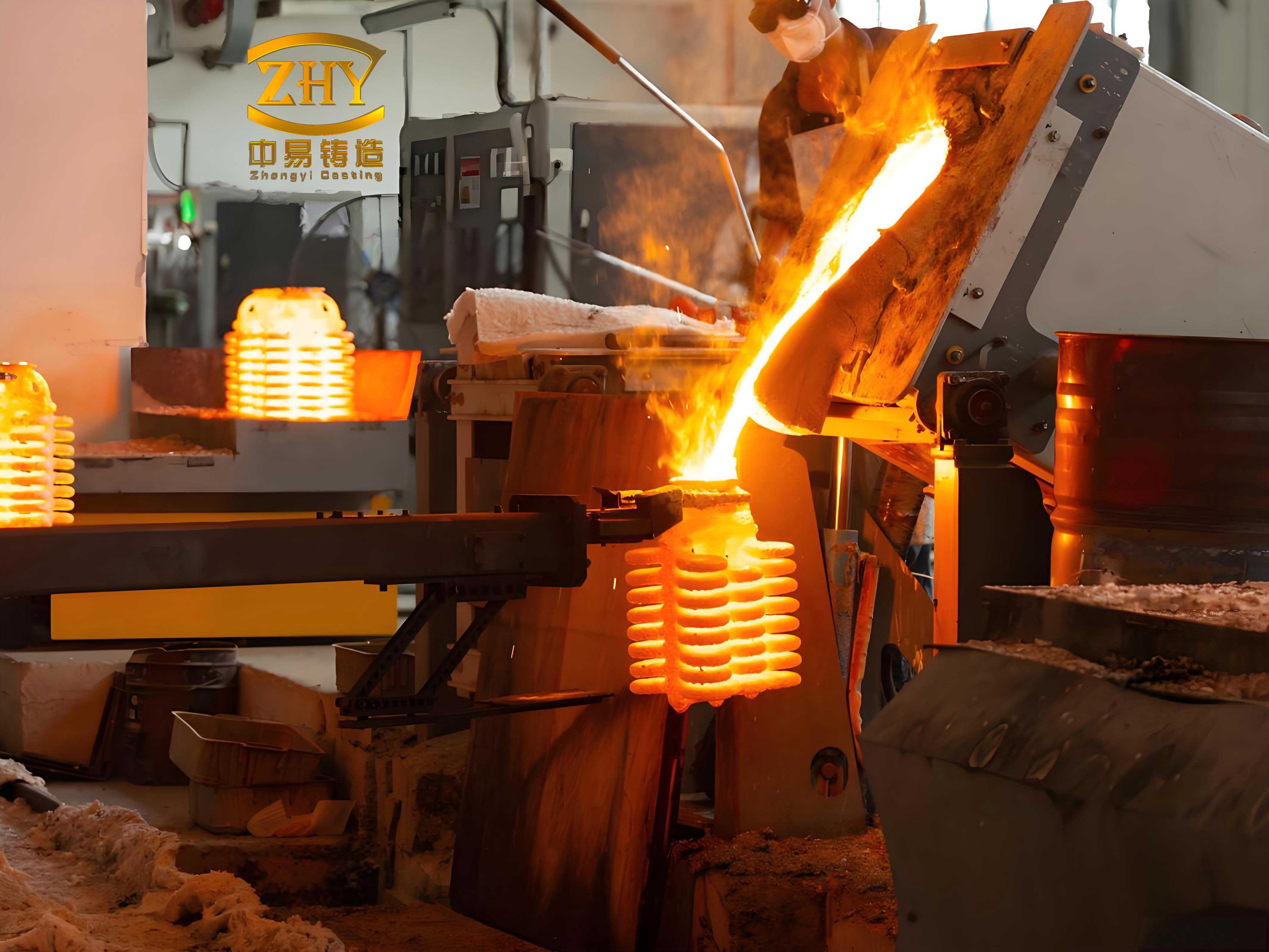
I first became involved with the compression system guide support because it is one of those components whose service duty is easy to underestimate until one studies the load path. The part sits inside a related assembly and must carry the rod-drop force when a choke plug assembly or a secondary source assembly falls inside the reactor. In the original manufacturing route, the guide cylinder and the support plate were produced separately by machining and then joined by welding. That welded route could meet the basic strength requirement, but I saw clear opportunities to improve stiffness, dimensional consistency, and fatigue resistance by converting the component to a one-piece precision casting. The geometry is a hollow cylindrical guide with an upper cylindrical bore, a middle conical transition bore, and a lower small cylindrical bore. At its lower end, the cylinder joins a square support plate that behaves as a ribbed perforated membrane. The plate contains four large flow holes and twenty-four assembly holes arranged in specific orientations. Because the wall transitions, rib network, and hole pattern are all integrated, the component is difficult to cast by conventional sand methods. I therefore chose lost wax casting with a silica-sol shell system as the core process, followed by heat treatment and finish machining. The figure below shows a representative precision investment casting example from the same family of manufacturing practice.
In my first review of the drawing, I separated the component into two functional regions: the cylindrical guide region, which controls alignment and sliding, and the support plate region, which controls load distribution and flow. That separation was useful because the casting risks in the two regions are different. The cylinder is thick and tends to form shrinkage porosity if feeding is not adequate. The plate is thin and ribbed and tends to form cold shuts, misruns, or incomplete filling if pouring temperature and filling velocity are not controlled. The material is CF3 cast steel, which requires careful melting practice, a proper deoxidation step, and a quench heat treatment after casting. I also had to respect non-destructive testing requirements, especially radiographic testing, because internal soundness is critical. My approach was therefore not simply to reproduce the shape in wax, but to design the entire lost wax casting route around feeding, cooling, dimensional compensation, and inspection.
Before I describe the details, I want to state the central process logic that guided every decision. In lost wax casting, the wax pattern is not a temporary convenience; it is the first dimensional and thermal model of the final part. Every wax shrinkage, every shell expansion, every pouring turbulence, and every cooling gradient is transferred into the final metal. If I control the wax, I control the shell. If I control the shell, I control the fill. If I control the fill and the solidification, I control the internal quality. If I control the internal quality, I can satisfy the radiographic and mechanical requirements. This chain is the reason I treated the wax mold design, wax injection, tree assembly, shell building, dewaxing, melting, pouring, heat treatment, and machining as one integrated system rather than as separate operations.
The first quantitative check I made was to compare the solidification modulus of the thick cylinder with that of the thin plate ribs. Using Chvorinov’s rule, the solidification time of a section can be estimated as
$$t_s = B \left(\frac{V}{A}\right)^2$$
where \(t_s\) is the solidification time, \(B\) is a constant that depends on the mold material and the metal, \(V\) is the volume of the section, and \(A\) is the heat-transfer surface area. The ratio \(V/A\) is the modulus \(M\). For the cylinder, I calculated
$$M_c = \frac{V_c}{A_c}$$
and for the ribs I calculated
$$M_r = \frac{V_r}{A_r}$$
To achieve directional solidification toward the gate and header, I needed
$$M_r < M_c < M_{header}$$
This inequality became my first feeding criterion. If the header modulus is not larger than the casting modulus, the header cannot feed the last solidifying region. If the rib modulus is too close to the cylinder modulus, the ribs may freeze before the cylinder is fed, or the cylinder may draw metal from the ribs and create shrinkage. I used this criterion to size the cross-shaped header and the main sprue. I also used the Niyama criterion as a secondary check for shrinkage porosity:
$$\frac{G}{\sqrt{R}} \ge 0.8$$
where \(G\) is the temperature gradient and \(R\) is the cooling rate. In practical terms, I wanted a steep gradient along the feeding path and a moderate cooling rate in the isolated plate regions. That is why I later used a wet sand bed on the lower half of the shell and an insulating blanket on the header. The wet sand increases the cooling rate in the plate and cylinder lower regions, while the insulation keeps the header liquid longer. The result is a feeding channel that stays open while the thin ribs freeze first and the thick cylinder freezes last toward the header.
Table 1 summarizes the main features of the guide support and the casting challenges I associated with each feature.
| Feature | Geometric description | Primary casting challenge | My process countermeasure |
|---|---|---|---|
| Upper guide bore | Cylindrical bore at the top of the guide cylinder | Dimensional distortion, ovality, and shrinkage porosity in thick wall | Cold wax core, split mold, controlled wax injection, header feeding |
| Conical transition | Tapered bore between upper and lower bore | Shell cracking at sharp transition and incomplete fill | Rounded transitions, proper slurry coverage, controlled pouring temperature |
| Lower small bore | Small cylindrical bore at the bottom | Core shift and poor concentricity | Rigid core support, datum control, finish machining after casting |
| Square support plate | Flat plate with rib network | Cold shut, misrun, and warpage | Cross-shaped tree, wet sand cooling, adequate pouring superheat |
| Four large flow holes | Large openings for flow passage | Shell erosion and dimensional variation | Robust shell build, ceramic core stability, controlled fill rate |
| Twenty-four assembly holes | Small holes arranged in specific orientations | Position error and drill breakout | Cast near-net shape, then machine with dedicated fixture |
| Ribbed plate junction | Intersection of plate and cylinder | Hot spot and shrinkage porosity | Chill from wet sand, feed path from header, Niyama check |
Table 2 lists the material and property requirements that I used to define the process window. I treated these requirements as acceptance criteria for the lost wax casting route, not as post-casting wishes.
| Requirement category | Target or method | Process implication |
|---|---|---|
| Base material | CF3 cast steel | Controlled charge, clean furnace, deoxidation |
| Chemical composition | Complies with material specification | Strict charge ratio, no residual contamination |
| Metallography | Acceptable microstructure | Proper quench and uniform austenitizing |
| Penetrant testing | No unacceptable surface indications | Smooth wax surface, clean shell, controlled pour |
| Radiographic testing | No unacceptable internal porosity | Directional solidification, adequate feeding |
| Intergranular corrosion | Passes specified test | Correct composition and heat treatment |
| Mechanical properties | Tensile, yield, elongation, impact | Sound casting, no porosity, proper quench |
| Hardness | Within specified range | Controlled austenitizing and cooling |
I then moved to the wax mold design. The component is not symmetric in a way that allows a simple two-part mold without care. The cylindrical region is thick and can shrink unevenly. The square plate has ribs and holes that can lock the wax pattern into the mold. I therefore divided the product into two main portions: the cylindrical portion and the main body portion. This split allowed the wax pattern to be removed without tearing the thin rib sections. I also used a cold wax core for the thick cylindrical portion. The cold wax core accelerated local cooling and helped prevent shrinkage cavities on the wax surface. I designed the parting line so that the ribs, holes, and plate edges would not be damaged during extraction. The injection gates and the tree connection points were integrated into the mold so that tree assembly could be performed without additional wax welding at critical sections.
For dimensional compensation, I applied a wax shrinkage factor and a subsequent shell and metal shrinkage factor. The mold dimension \(D_m\) for a target part dimension \(D_p\) was estimated as
$$D_m = D_p \left(1 + S_w\right)$$
where \(S_w\) is the wax shrinkage allowance. In practice, I used a range rather than a single value because the shrinkage depends on section thickness, injection pressure, and cooling rate. The total dimensional allowance from wax to final part is not a single constant. I treated it as a sum:
$$S_{total} = S_w + S_s + S_m + S_{mach}$$
where \(S_w\) is wax shrinkage, \(S_s\) is shell expansion or contraction during dewaxing and firing, \(S_m\) is metal contraction during solidification and cooling, and \(S_{mach}\) is the machining allowance. I used this sum to set the mold cavity dimensions and the machining stock. Table 3 shows the mold design parameters I recorded for the first article.
| Mold design item | Decision | Reason |
|---|---|---|
| Parting strategy | Split into cylindrical portion and main body portion | Simplify extraction and prevent wax deformation |
| Cylindrical core | Cold wax core | Accelerate cooling in thick section and reduce shrinkage |
| Draft angle | Minimum 1.5 degrees on deep draws | Reduce extraction force and wax tearing |
| Wax shrinkage allowance | Adaptive based on section thickness | Different sections shrink differently |
| Gate location | Integrated with tree connection | Reduce manual wax welding and improve consistency |
| Locating features | Male-female alignment bosses | Ensure exact registration when assembling wax halves |
| Insert for holes | Removable pins for twenty-four small holes | Preserve hole positions in wax and reduce drilling stock |
| Cooling provision | Internal water passages in thick mold sections | Reduce cycle time and prevent local overheating |
The wax injection parameters were critical. I used the settings in Table 4 for the first production trial. The storage cylinder temperature was kept at \(72 \pm 3\,^\circ\mathrm{C}\), and the injection cylinder temperature was kept at \(52 \pm 2\,^\circ\mathrm{C}\). The injection time was \(30\) to \(40\) seconds, and the injection pressure was \(22\) to \(25\,\mathrm{kg/cm^2}\). I used water cooling and arranged the wax patterns neatly after complete cooling. I did not use any ceramic core or urea core for this route because the cold wax core was sufficient for the thick cylinder. I also avoided the use of a wax block or a shaping fixture during the first trial, because I wanted to observe the natural shrinkage behavior before adding constraints.
| Parameter | Setting | Parameter | Setting |
|---|---|---|---|
| Wax storage temperature | \(72 \pm 3\,^\circ\mathrm{C}\) | Injection time | \(30\) to \(40\,\mathrm{s}\) |
| Injection cylinder temperature | \(52 \pm 2\,^\circ\mathrm{C}\) | Injection pressure | \(22\) to \(25\,\mathrm{kg/cm^2}\) |
| Cooling time in mold | \(0\,\mathrm{s}\) | Cooling method | Water cooling |
| Pattern placement | Neat and separated | Core type | Cold wax core only |
During wax injection, I watched for three defects: surface sink, incomplete fill, and deformation during extraction. Surface sink usually means the injection pressure is too low or the cooling time is too short. Incomplete fill usually means the injection temperature is too low or the gate is too restrictive. Deformation usually means the pattern was removed before it had enough green strength. I used the Hagen-Poiseuille relationship as a qualitative guide for flow through the wax feed channels:
$$Q = \frac{\pi \Delta P R^4}{8 \mu L}$$
where \(Q\) is the volumetric flow rate, \(\Delta P\) is the pressure drop, \(R\) is the channel radius, \(\mu\) is the dynamic viscosity, and \(L\) is the channel length. This equation told me that small changes in gate radius have a very large effect on flow rate. That is why I designed the gates with generous radii and kept the flow length as short as possible. I also checked the Reynolds number for the wax flow to avoid turbulent folding:
$$Re = \frac{\rho v D}{\mu}$$
In the wax injection regime, the flow is usually laminar, so the main risk is not turbulence but premature freezing and incomplete reproduction of fine features. I therefore balanced pressure and temperature to fill the mold before the wax viscosity rose too high. Table 5 shows the wax pattern defect controls I used.
| Wax defect | Likely cause | Control action |
|---|---|---|
| Surface sink | Low pressure, short injection time, local hot spot | Increase pressure, extend injection time, improve mold cooling |
| Incomplete fill | Low wax temperature, narrow gate, entrapped air | Raise injection temperature, enlarge gate, add vent |
| Flash | Excessive pressure, worn parting line | Reduce pressure, maintain mold surface |
| Deformation | Early extraction, uneven cooling | Allow full cooling, use support tray, avoid stacking |
| Parting line step | Mold misalignment | Check alignment pins and closing force |
| Surface roughness | Dirty mold or low wax temperature | Clean mold, adjust temperature, inspect wax batch |
After the wax pattern was removed, I placed it in water to cool completely. Once cooled, I inspected the parting line and the gate area. I then trimmed the parting line until it was smooth and free of knife marks. The wax pattern surface had to be clean and free of any depression or protrusion. When the two halves were assembled, I aligned the locating features completely and used bonding wax to hold them together. I then applied hot wax along the joint and allowed it to fuse the two halves. After cooling, I scraped away excess wax and checked the joint again. I did not allow any gap, mismatch, or raised bead on the product surface. I also checked that no water was present on the pattern before tree assembly.
The tree assembly was the next major step. Because the guide support has a long cylindrical section and a thin ribbed plate, I used a cross-shaped header. This header ensured that the main sprue had enough steel to feed the thick cylinder and that the surrounding small gates had sufficient flow for the plate and ribs. I selected the sprue rod, arranged the patterns uniformly, and kept the tree clean and free of dust. The tree had to be free of weak joints, gaps, and wax droplets. The sprue rod had to be free of holes, flash, and sharp corners. I strictly prohibited assembling the header or product while any water was present. I also designed the test sample to be taken longitudinally during tree assembly so that the sample would represent the same thermal history as the casting.
I estimated the required header volume using a simple feeding ratio:
$$V_{header} \ge \beta V_{casting} + V_{feed}$$
where \(V_{header}\) is the header volume, \(V_{casting}\) is the casting volume, \(V_{feed}\) is the volume needed to compensate for liquid and solidification shrinkage, and \(\beta\) is a safety factor. For this component, I used a conservative \(\beta\) because the cylinder is thick and the radiographic requirement is strict. Table 6 shows the tree assembly parameters I used.
| Tree parameter | Setting | Reason |
|---|---|---|
| Header type | Cross-shaped header | Provide sufficient steel for feeding and distribute flow |
| Header construction | One T1-9 plus two wax bars of \(50 \times 50 \times 75\,\mathrm{mm}\) | Create a robust central reservoir |
| Header bottom | Flattened with a hot plate | Ensure stable positioning and uniform contact |
| Gate attachment | Firmly welded, no virtual welding | Prevent gate detachment and turbulence |
| Pattern spacing | Uniform around the sprue | Promote even shell drying and heat distribution |
| Cleanliness | No dust, no wax droplets on the product | Prevent shell inclusions and surface defects |
| Water contact | Not permitted during assembly | Avoid shell defects and wax separation |
| Sampling location | Longitudinal sample attached to the tree | Representative mechanical test specimen |
Shell building followed. I used a silica-sol lost wax casting system because it provides good surface finish and dimensional stability. The face coat is the most important layer for surface quality. I used zircon flour for the face slurry and zircon sand for the stucco. The face slurry viscosity was controlled between \(36\) and \(40\) seconds using a Zahn cup. The zircon sand size was \(80\) to \(120\) mesh. The room temperature was maintained between \(20\) and \(26\,^\circ\mathrm{C}\), and the relative humidity was kept between \(60\%\) and \(70\%\). The face coat was dried for \(6\) to \(12\) hours. For the backup layers, I used mullite flour and mullite sand. The second layer slurry viscosity was \(20\) to \(24\) seconds, and the sand was \(60\) to \(80\) mesh. The third through fifth layers used a slurry viscosity of \(12\) to \(16\) seconds and sand of \(16\) to \(30\) mesh. The seal coat used a slurry viscosity of \(8\) to \(12\) seconds. The backup layers were dried for at least \(4\) hours at \(20\) to \(26\,^\circ\mathrm{C}\) and \(40\%\) to \(60\%\) relative humidity. Table 7 lists the shell building parameters in detail.
| Shell layer | Slurry material | Slurry viscosity (Zahn cup, s) | Stucco material | Room temperature (\(^\circ\mathrm{C}\)) | Humidity RH | Drying time |
|---|---|---|---|---|---|---|
| Face coat | Zircon flour | \(36\) to \(40\) | Zircon sand, \(80\) to \(120\) mesh | \(20\) to \(26\) | \(60\%\) to \(70\%\) | \(6\) to \(12\,\mathrm{h}\) |
| Second layer | Mullite flour | \(20\) to \(24\) | Mullite sand, \(60\) to \(80\) mesh | \(20\) to \(26\) | \(40\%\) to \(60\%\) | \(\ge 4\,\mathrm{h}\) |
| Third layer | Mullite flour | \(12\) to \(16\) | Mullite sand, \(16\) to \(30\) mesh | \(20\) to \(26\) | \(40\%\) to \(60\%\) | \(\ge 4\,\mathrm{h}\) |
| Fourth layer | Mullite flour | \(12\) to \(16\) | Mullite sand, \(16\) to \(30\) mesh | \(20\) to \(26\) | \(40\%\) to \(60\%\) | \(\ge 4\,\mathrm{h}\) |
| Fifth layer | Mullite flour | \(12\) to \(16\) | Mullite sand, \(16\) to \(30\) mesh | \(20\) to \(26\) | \(40\%\) to \(60\%\) | \(\ge 4\,\mathrm{h}\) |
| Seal coat | Mullite flour | \(8\) to \(12\) | None | \(20\) to \(26\) | \(40\%\) to \(60\%\) | \(\ge 4\,\mathrm{h}\) |
From the second layer onward, I used a robotic shell-making system. The robot reduced operator fatigue and produced a more uniform shell thickness and density than manual dipping. The robot could work continuously for twenty-four hours, and the fast-dry room shortened the drying time. In my trials, the shell could usually be taken offline about twenty-four hours after the start of shell building. This cycle was about one quarter of the conventional manual shell-making cycle, which improved productivity significantly. I still inspected the face coat manually because the face coat controls the surface finish and cannot be left entirely to automation.
I modeled the shell thickness growth as a sum of layer contributions:
$$t_n = t_0 + \sum_{i=1}^{n} \Delta t_i$$
where \(t_n\) is the total shell thickness after \(n\) layers, \(t_0\) is the initial face coat thickness, and \(\Delta t_i\) is the thickness added by each subsequent layer. I also used a simple drying model to estimate residual moisture:
$$M(t) = M_0 e^{-kt}$$
where \(M(t)\) is the moisture content at time \(t\), \(M_0\) is the initial moisture content, and \(k\) is a drying constant that depends on temperature, humidity, and air flow. This model helped me decide when the shell was dry enough for dewaxing. In practice, I used the drying time in Table 7 as the minimum, and I verified dryness by weight loss and by visual inspection of the shell color and surface.
After the shell was fully dried, I used a steam dewaxing autoclave to remove the wax. Before dewaxing, I cleaned the flash from the sprue cup. I set the autoclave pressure to \(0.5\) to \(0.6\,\mathrm{MPa}\), the vent time to more than \(50\) seconds, the dewaxing time to \(10\) to \(15\) minutes, and the temperature to \(150\) to \(160\,^\circ\mathrm{C}\). After dewaxing, I placed the sprue cup downward to prevent dust and debris from entering the shell. I also inspected and cleaned the filter screen regularly and replaced it when necessary. Table 8 lists the dewaxing parameters.
| Dewaxing parameter | Setting |
|---|---|
| Placement | Sprue cup downward |
| Pressure | \(0.5\) to \(0.6\,\mathrm{MPa}\) |
| Vent time | \(>50\,\mathrm{s}\) |
| Dewaxing time | \(10\) to \(15\,\mathrm{min}\) |
| Temperature | \(150\) to \(160\,^\circ\mathrm{C}\) |
Melting and pouring were the most critical steps for internal quality. The component must pass radiographic testing, so I treated every melting decision as a quality decision. I cleaned the furnace completely before charging. I removed all slag and residual steel from the previous heat because residual elements can shift the composition and harm the mechanical properties. I followed the charge sheet strictly for CF3 cast steel. The pouring temperature was controlled at \(1550 \pm 10\,^\circ\mathrm{C}\). The shell was fired at \(1100 \pm 20\,^\circ\mathrm{C}\) for at least \(90\) minutes. The charge ratio of new material to recycled material was at least \(60\!:\!40\). I used electrostatic slag removal. For deoxidation, I added electrolytic manganese, ferrosilicon, and calcium silicon at \(50\) to \(70\,\mathrm{g}\) each. I used a heating and insulating agent, did not use clamping, and cooled the shell on a wet sand bed. Table 9 summarizes the melting and pouring parameters.
| Melting and pouring parameter | Setting |
|---|---|
| Shell firing temperature | \(1100 \pm 20\,^\circ\mathrm{C}\) |
| Shell firing time | \(\ge 90\,\mathrm{min}\) |
| New-to-recycled charge ratio | \(\ge 60\!:\!40\) |
| Pouring temperature | \(1550 \pm 10\,^\circ\mathrm{C}\) |
| Slag removal | Electrostatic slag removal |
| Deoxidation additions | Electrolytic manganese, ferrosilicon, calcium silicon, \(50\) to \(70\,\mathrm{g}\) each |
| Heating and insulating agent | Used |
| Clamping | Not used |
| Cooling method | Wet sand bed |
The pouring design was aimed at two defects: shrinkage porosity in the long cylinder and cold shuts in the thin plate ribs. I used the wet sand bed on the lower half of the shell so that the plate and lower cylinder would freeze first. I wrapped the header with insulating cotton so that the header would freeze last. This arrangement created a favorable temperature gradient from the thin plate toward the header. The feeding path remained open while the plate solidified, and the header continued to supply liquid metal to the cylinder. I also controlled the pouring rate. The Bernoulli relation for the pouring stream is
$$v = \sqrt{2gh}$$
where \(v\) is the velocity, \(g\) is the gravitational acceleration, and \(h\) is the metallostatic head. The volumetric pouring rate is
$$Q = A_g v$$
where \(A_g\) is the gate cross-sectional area. If the pouring rate is too low, the metal may freeze before filling the thin ribs. If the pouring rate is too high, the stream may become turbulent, entrain gas, and erode the shell. I therefore adjusted the sprue height and gate area to maintain a smooth, progressive fill. I also checked the thermal gradient along the feeding path using
$$G = \frac{T_1 – T_2}{x_2 – x_1}$$
and the cooling rate using
$$R = \frac{T_1 – T_2}{t}$$
These simple estimates were enough to guide the first article and to set the process window for the production trial. Table 10 lists the main casting defects, their causes, and the countermeasures I used.
| Casting defect | Likely cause | Countermeasure |
|---|---|---|
| Shrinkage porosity in cylinder | Insufficient feeding, low header modulus, steep cooling | Increase header size, insulate header, use wet sand on lower shell |
| Cold shut in plate ribs | Low pouring temperature, slow fill, thin section | Raise pouring temperature, increase gate area, improve fill rate |
| Misrun at plate edge | Insufficient superheat, shell too cold | Increase shell firing temperature, shorten transfer time |
| Gas porosity | Turbulent flow, wet shell, dirty charge | Improve pouring smoothness, verify shell dryness, clean charge |
| Sand inclusion | Shell erosion, weak shell, dirty sprue | Increase shell strength, clean sprue cup, control fill rate |
| Hot spot at rib junction | Mass concentration, slow local cooling | Use local chill, adjust rib design, feed from header |
| Warpage | Uneven cooling, poor support | Uniform sand bed, controlled cooling, fixture if needed |
After pouring and cooling, I proceeded to heat treatment. The material is CF3 cast steel, and the component requires quenching. I used a sealed pit resistance furnace with an air atmosphere. The austenitizing temperature was \(1100\,^\circ\mathrm{C}\), and the holding time was \(80\) minutes. I loaded the parts uniformly and avoided stacking. After the hold, I removed the parts and quenched them rapidly in water. The initial water temperature was not allowed to exceed \(50\,^\circ\mathrm{C}\). I left the parts in the water until they were completely cooled before removing them. The cooling rate during quenching can be estimated from the lumped-capacitance approximation:
$$\dot{T} = -\frac{hA(T – T_\infty)}{\rho V c_p}$$
where \(\dot{T}\) is the cooling rate, \(h\) is the heat-transfer coefficient, \(A\) is the surface area, \(T\) is the part temperature, \(T_\infty\) is the quenchant temperature, \(\rho\) is the density, \(V\) is the volume, and \(c_p\) is the specific heat. This equation shows why agitation and water temperature control matter. If the water temperature is too high, the cooling rate drops and the mechanical properties may not meet the requirement. If the water temperature is too low, the thermal shock may be excessive. I used \(50\,^\circ\mathrm{C}\) as the upper limit and ensured rapid transfer from the furnace to the quench tank. Table 11 shows the heat treatment schedule.
| Heat treatment step | Parameter |
|---|---|
| Furnace type | Sealed pit resistance furnace |
| Atmosphere | Air |
| Austenitizing temperature | \(1100\,^\circ\mathrm{C}\) |
| Holding time | \(80\,\mathrm{min}\) |
| Loading | Uniform, no stacking |
| Quench medium | Water |
| Initial water temperature | \(\le 50\,^\circ\mathrm{C}\) |
| Removal from water | After complete cooling |
After heat treatment, I moved to machining. The support plate top and bottom faces, the guide cylinder, and the twenty-four assembly holes required machining to meet verticality, flatness, and position requirements. The main difficulty was the position of the twenty-four small holes relative to datum A, which is the cylinder axis. Because of the component geometry, I could not machine all features in one setup. I first used a CNC lathe to turn the cylindrical portion to size. I then used a machining center to drill and ream the twenty-four holes. I designed a dedicated fixture to hold the part by datum A and datum C so that the position tolerance could be maintained. The true position of each hole was checked using
$$TP = 2\sqrt{(x – x_0)^2 + (y – y_0)^2}$$
where \(TP\) is the true position diameter, \((x,y)\) is the measured hole location, and \((x_0,y_0)\) is the nominal location. I also checked perpendicularity of datum A to datum C and flatness of the support plate. Table 12 lists the machining requirements and the fixture design features.
| Machining item | Requirement | Fixture or method |
|---|---|---|
| Support plate top face | Flatness and surface finish | CNC machining center with face mill |
| Support plate bottom face | Flatness and parallelism | CNC machining center with face mill |
| Guide cylinder outer surface | Concentricity and diameter | CNC lathe with soft jaws |
| Upper cylindrical bore | Diameter and roundness | CNC lathe or boring head |
| Conical transition bore | Profile and surface finish | CNC lathe with profile tool |
| Lower small bore | Diameter and concentricity | CNC lathe with boring bar |
| Twenty-four assembly holes | Position relative to datum A | Dedicated fixture and machining center |
| Datum A to datum C perpendicularity | Perpendicularity tolerance | Fixture with axial and planar locating surfaces |
I also used a process capability check after machining. The capability index is
$$C_{pk} = \min\left(\frac{USL – \mu}{3\sigma}, \frac{\mu – LSL}{3\sigma}\right)$$
where \(USL\) is the upper specification limit, \(LSL\) is the lower specification limit, \(\mu\) is the process mean, and \(\sigma\) is the process standard deviation. I calculated \(C_{pk}\) for the critical hole position, cylinder diameter, and plate flatness. For the first article, the values were acceptable, but I identified the hole position as the least capable characteristic. That is why I later improved the fixture and added an in-process probing step. Table 13 shows a summary of the first-article inspection results.
| Inspection item | Method | Result | Action |
|---|---|---|---|
| Chemical composition | Spectrochemical analysis | Within specification | Accept |
| Metallography | Microscopic examination | Acceptable microstructure | Accept |
| Penetrant testing | Dye penetrant | No unacceptable indications | Accept |
| Radiographic testing | X-ray inspection | No unacceptable internal porosity | Accept |
| Intergranular corrosion | Corrosion test | Pass | Accept |
| Mechanical properties | Tensile and impact tests | Meets specification | Accept |
| Hardness | Hardness tester | Within range | Accept |
| Dimensional inspection | CMM and gauges | Within drawing requirements | Accept |
The yield of the lost wax casting route can be expressed in two ways. The first is the casting yield by weight:
$$Y = \frac{W_{casting}}{W_{poured}} \times 100\%$$
where \(W_{casting}\) is the weight of the finished casting and \(W_{poured}\) is the weight of metal poured into the mold. The second is the volumetric tree efficiency:
$$\eta = \frac{V_{casting}}{V_{tree}} \times 100\%$$
where \(V_{casting}\) is the casting volume and \(V_{tree}\) is the total volume of the tree including the header, sprue, and gates. In my first trial, the yield was lower than I wanted because the cross-shaped header was built from a T1-9 section and two wax bars. That construction was robust, but it was also bulky and labor-intensive. The header structure increased the tree volume and reduced the yield. For future batch production, I would design a dedicated header mold. That mold would simplify the tree structure, reduce manual assembly time, and improve the yield. Table 14 compares the current route with the proposed future route.
| Factor | Current lost wax casting route | Proposed future route |
|---|---|---|
| Header construction | Cross-shaped header from T1-9 and wax bars | Dedicated molded header |
| Tree assembly labor | High | Lower |
| Tree volume | Large | Optimized |
| Casting yield | Moderate | Higher |
| Process repeatability | Good but dependent on operator skill | Better because header is standardized |
| Shell building | Robot-assisted | Robot-assisted with optimized tree spacing |
| Pouring | Wet sand bed plus header insulation | Same principle with improved thermal control |
| Machining | Dedicated fixture | Improved fixture with in-process probing |
I also paid attention to the measurement system because the twenty-four holes and the cylinder datum are the most demanding characteristics. The standard deviation of a measured characteristic is
$$\sigma = \sqrt{\frac{\sum_{i=1}^{n}(x_i – \mu)^2}{n – 1}}$$
where \(x_i\) are the individual measurements, \(\mu\) is the mean, and \(n\) is the number of measurements. I used this value to monitor process drift. If the standard deviation increased, I looked for a change in wax injection, shell drying, pouring temperature, heat treatment, or fixture wear. In my experience, the two most common causes of dimensional drift in this lost wax casting route are wax pattern distortion during storage and shell movement during dewaxing. Both can be controlled by handling discipline and by keeping the wax pattern supported until it is fully cooled.
Another important relationship is the surface roughness of the cast and machined surfaces. For a machined surface, the arithmetic average roughness can be approximated from the profile:
$$R_a = \frac{1}{L}\int_0^L |y(x)|\,dx$$
where \(L\) is the sampling length and \(y(x)\) is the profile height. I used this definition to explain why the face coat quality matters even for surfaces that are later machined. A rough cast surface increases the local machining stock variation, which in turn changes the cutting force and the final flatness. A smooth face coat reduces this variation. That is why I kept the face slurry viscosity between \(36\) and \(40\) seconds and used fine zircon sand. The face coat is not a cosmetic layer in lost wax casting; it is a dimensional and machining input.
I also considered the thermal history of the casting after pouring. The cooling time after solidification can be approximated by
$$t_c = \frac{\rho V c_p}{hA} \ln\left(\frac{T_i – T_\infty}{T_f – T_\infty}\right)$$
where \(t_c\) is the cooling time, \(T_i\) is the initial temperature, \(T_f\) is the final temperature, and the other symbols have their usual meanings. This equation is another reason I used the wet sand bed and the insulated header. The wet sand increases \(h\) on the lower shell and reduces the cooling time in the plate, while the insulation reduces \(h\) on the header and extends the feeding time. The combination is a simple but effective way to create directional solidification without complex chills.
When I reviewed the overall route, I found that lost wax casting offers several advantages for this guide support. First, it produces a one-piece component with integrated ribs and holes, which eliminates the welded joints of the original route. Second, it provides better repeatability of the internal geometry because the wax pattern and shell are produced from a mold. Third, it allows the use of a high-integrity shell system that can reproduce fine details. Fourth, it supports radiographic inspection because the shell can be designed for proper feeding. Fifth, it can be combined with heat treatment and machining to meet the final drawing requirements. The main challenges are the cost of the wax mold, the need for careful wax handling, the sensitivity of the shell to drying conditions, and the importance of pouring temperature control. These challenges are manageable with the process windows I established.
I also developed a failure-mode checklist for the lost wax casting route. The purpose was to connect each potential defect to a specific process variable so that corrective action would be fast. Table 15 shows the checklist.
| Failure mode | Process variable to check first | Secondary check | Corrective action |
|---|---|---|---|
| Wax pattern sink | Injection pressure | Wax temperature, cooling time | Increase pressure, adjust temperature, improve mold cooling |
| Wax pattern deformation | Cooling time before extraction | Support method, storage temperature | Extend cooling, support pattern, control storage |
| Shell crack | Drying rate | Layer thickness, humidity | Slow drying, increase layer strength, control humidity |
| Shell surface defect | Face slurry viscosity | Sand size, dipping motion | Adjust viscosity, replace sand, improve dipping |
| Incomplete fill | Pouring temperature | Gate area, shell temperature | Raise temperature, enlarge gate, raise shell firing temperature |
| Shrinkage porosity | Header modulus | Cooling gradient, insulation | Increase header, insulate header, use wet sand |
| Gas porosity | Pouring turbulence | Shell dryness, charge cleanliness | Improve fill, dry shell, clean charge |
| Warpage | Cooling uniformity | Sand bed support, stacking | Uniform cooling, avoid stacking, use fixture if needed |
| Dimensional error | Wax shrinkage allowance | Shell expansion, machining stock | Adjust mold dimensions, verify shrinkage factors |
| Hardness variation | Quench temperature | Loading pattern, transfer time | Control water temperature, improve loading, reduce transfer time |
I also used a simple production cycle estimate. If the shell-building cycle is \(t_{shell}\), the dewaxing and firing cycle is \(t_{dewax}\), the melting and pouring cycle is \(t_{pour}\), the heat treatment cycle is \(t_{heat}\), and the machining cycle is \(t_{mach}\), then the total cycle time for one batch is approximately
$$t_{total} = t_{shell} + t_{dewax} + t_{pour} + t_{heat} + t_{mach}$$
In my trials, the robot-assisted shell building reduced \(t_{shell}\) significantly. The fast-dry room allowed the shell to be ready in about twenty-four hours. The dewaxing and firing steps were batch operations, so they could be scheduled in parallel with other batches. The pouring step was the critical path because the shell had to be at temperature and the metal had to be at the correct composition and temperature. The heat treatment and machining steps were also batch operations, but they could be sequenced after pouring. The overall effect was a stable production route with predictable lead time.
I also want to emphasize the importance of the test sample. I designed the sample to be taken longitudinally during tree assembly. The sample must experience the same melting, pouring, and heat treatment history as the casting. If the sample is made separately, it may not represent the casting. The sample location on the tree must be chosen so that it solidifies under similar conditions to the critical section of the casting. In this case, the longitudinal sample was attached to the tree in a way that allowed it to cool with the header and the cylinder. That gave me confidence that the mechanical test results represented the actual component.
For the chemical composition, I used spectrochemical analysis on a sample from the same heat. For the metallographic examination, I checked the microstructure for excessive segregation, porosity, and undesirable phases. For penetrant testing, I inspected the machined and cast surfaces for cracks and surface porosity. For radiographic testing, I inspected the thick cylinder and the plate-to-cylinder junction. For intergranular corrosion, I followed the specified test method. For mechanical properties, I tested tensile strength, yield strength, elongation, and impact energy. For hardness, I checked the quenched and tempered condition. All results met the drawing technical conditions. Table 16 summarizes the validation results and the corresponding acceptance criteria.
| Validation test | Acceptance criterion | Result | Conclusion |
|---|---|---|---|
| Chemical composition | Within CF3 specification | Within specification | Pass |
| Metallography | Acceptable microstructure | Acceptable | Pass |
| Penetrant testing | No unacceptable indications | No unacceptable indications | Pass |
| Radiographic testing | No unacceptable porosity | No unacceptable porosity | Pass |
| Intergranular corrosion | No susceptibility | Pass | Pass |
| Tensile strength | \(\ge\) specified minimum | Above minimum | Pass |
| Yield strength | \(\ge\) specified minimum | Above minimum | Pass |
| Elongation | \(\ge\) specified minimum | Above minimum | Pass |
| Impact energy | \(\ge\) specified minimum | Above minimum | Pass |
| Hardness | Within specified range | Within range | Pass |
My conclusion is that the lost wax casting route is technically sound for this guide support. The one-piece precision casting eliminates the welded joints of the original route and improves the strength and stiffness of the component. The process window I established covers wax injection, tree assembly, shell building, dewaxing, melting, pouring, heat treatment, and machining. The use of a cold wax core, a cross-shaped header, a zircon face coat, a robot-assisted shell system, a wet sand bed, an insulated header, and a dedicated machining fixture allowed the component to meet the radiographic, metallographic, corrosion, mechanical, and dimensional requirements. The main remaining opportunity is the header design. In the first trial, the header was assembled from existing wax sections, which increased labor and reduced yield. For batch production, I would design a dedicated header mold. That change would simplify the tree, shorten assembly time, improve yield, and make the lost wax casting process more repeatable.
I would also continue to monitor the process with statistical methods. For any critical characteristic, I would track the mean and standard deviation and calculate \(C_{pk}\). If \(C_{pk}\) falls below the target, I would investigate the wax injection pressure, the shell drying humidity, the pouring temperature, the quench water temperature, or the machining fixture. In my view, the success of lost wax casting for this component does not come from a single breakthrough. It comes from controlling many small variables in a consistent way. The wax must be injected with the right pressure and temperature. The shell must be built with the right viscosity and dried under the right humidity. The dewaxing must be complete without cracking the shell. The melt must be clean and deoxidized. The pour must be hot enough to fill the thin ribs but controlled enough to avoid turbulence. The header must remain liquid long enough to feed the thick cylinder. The quench must be fast enough to develop the required properties but uniform enough to avoid distortion. The machining fixture must hold datum A and datum C correctly. When all of these conditions are met, the lost wax casting route produces a guide support that meets the drawing and performs reliably in service.
For similar components with a thick cylinder, a thin ribbed plate, and a demanding radiographic requirement, I would recommend the same general approach. Start with the feeding modulus and the Niyama criterion. Design the wax mold with a split that protects thin features. Use a cold wax core for thick sections. Control the face coat viscosity tightly. Use a cross-shaped or dedicated header that is large enough to feed the last solidifying region. Use a wet sand bed and header insulation to create directional solidification. Control the pouring temperature within a narrow band. Quench from the correct austenitizing temperature with controlled water temperature. Machine with a fixture that respects the datum structure. Validate with chemical, metallographic, penetrant, radiographic, corrosion, mechanical, and hardness tests. If the first article meets the requirements, then improve the header and fixture for production. This is the route I followed, and it gave me a reliable precision lost wax casting solution for the compression system guide support.