
In my extensive experience with ductile iron components, I have observed that ductile iron is more prone to casting defects compared to ordinary gray iron. These casting defects, if not properly addressed, often lead to the scrapping of parts, resulting in significant economic losses. Therefore, developing an effective welding repair process for ductile iron has been a critical and urgent challenge. The primary technical issues in welding repair of ductile iron can be summarized as follows: first, ensuring good graphitization and spheroidization of graphite in the weld metal; second, eliminating the chill white iron structure at the weld zone and the interface between the weld and base metal; and third, eliminating pin-hole porosity in the weld bead. These casting defects must be meticulously managed to restore the integrity and performance of the components.
Our systematic investigation into welding repair of ductile iron began in the early 1960s. Initially, we focused on achieving weld microstructures and mechanical properties comparable to the base metal. However, the persistent issue of pin-hole porosity in the weld remained unresolved until after multiple experiments over several years. The elimination of these pin-holes marked a breakthrough, essentially solving the core technical problems in ductile iron welding repair. Below, I detail our experimental approaches and production trials, emphasizing the use of optimized parameters to mitigate casting defects.
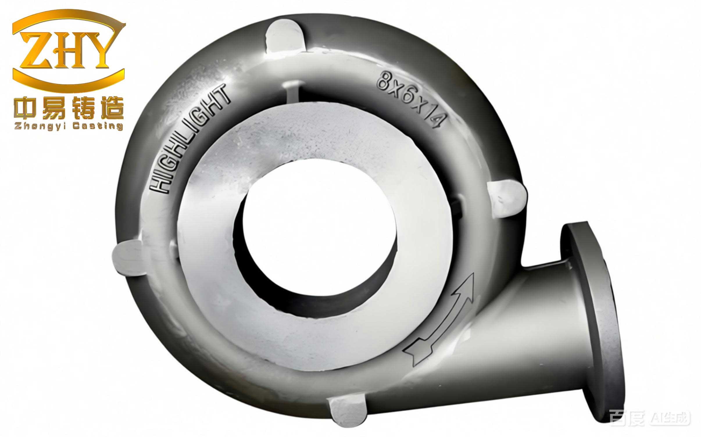
The presence of casting defects, such as shrinkage cavities, cracks, or inclusions, necessitates thorough removal before welding. The defective area must be cleaned until metallic luster is exposed, and for cracks, a groove should be prepared along the crack path. Preheating is essential for components prone to stress concentration or where weld shrinkage could induce new casting defects. We typically preheat to approximately 600°C, followed by slow cooling post-welding to prevent cracking. The welding process involves using specially designed filler rods and fluxes to control the microstructure and avoid common casting defects.
For ferritic base ductile iron, we conducted multiple welding trials. The key was to use filler rods with compositions derived from the base metal iron melt, supplemented with specific elements to promote graphitization and reduce carbides. The filler rod composition is critical in preventing casting defects like white iron formation. We formulated rods by adding silicon and magnesium to the base iron, with approximate compositional ranges: carbon 3.0-4.0%, silicon 3.0-4.5%, manganese below 0.5%, phosphorus below 0.1%, and sulfur below 0.02%. The rods were cast into semi-circular shapes with diameters of 5-8 mm, using green sand molds, and surface-treated by shot blasting and polishing. The flux composition included borax, soda ash, lime powder, and iron-silicon powder in specific proportions to shield the weld pool and reduce oxidation.
The experimental results for ferritic base ductile iron welding are summarized in Table 1, which outlines the chemical composition, mechanical properties, and outcomes related to casting defects. The table highlights how variations in silicon content and welding parameters affect graphitization and the presence of carbides.
| Trial | Base Metal Composition (wt%) | Mechanical Properties | Filler Rod Details | Flux | Heat Treatment | Results and Analysis |
|---|---|---|---|---|---|---|
| First | C: 3.8, Si: 2.5, Mn: 0.3, P: 0.05, S: 0.01 | σ_b: 45 kg/mm², δ: 15% | Semi-circular, 5 mm dia, from base iron with added Si, Mg, Cu | Borax 100% | Annealed at 900°C for 2 hours, furnace cooled | Poor graphitization, surface pores and other casting defects present; weld had sand holes and uneven fusion. |
| Second | C: 3.7, Si: 2.8, Mn: 0.25, P: 0.06, S: 0.012 | σ_b: 48 kg/mm², δ: 18% | Similar, but with dry mold casting for better surface | Borax 80%, Soda ash 20% | Annealed at 920°C for 3 hours | Reduced casting defects; still some white iron and incomplete fusion due to low flame temperature. |
| Third | C: 3.9, Si: 3.0, Mn: 0.2, P: 0.04, S: 0.008 | σ_b: 50 kg/mm², δ: 20% | Optimized Si addition, improved rod homogeneity | Borax 70%, Lime powder 20%, Fe-Si powder 10% | Annealed at 950°C for 4 hours | Better graphitization, but pin-hole casting defects persisted; weld interface showed carbides. |
| Fourth | C: 3.6, Si: 3.5, Mn: 0.15, P: 0.03, S: 0.005 | σ_b: 52 kg/mm², δ: 22% | High Si, low Mn, with added Al-Cu-Mg alloy | Borax 60%, Soda ash 20%, Lime powder 10%, Fe-Si powder 10% | Annealed at 980°C for 5 hours | Significant reduction in casting defects; weld microstructure nearly matched base metal, but pin-holes required further attention. |
From these trials, we derived a process specification for production: filler rods made from base iron with added silicon (3.5-4.5%), magnesium (0.04-0.06%), and sometimes copper or aluminum alloys; preheating to 600°C; using a neutral flame with stable adjustment; and post-weld annealing to eliminate carbides. The mechanical properties achieved were tensile strength (σ_b) of 50-55 kg/mm² and elongation (δ) of 18-25%, with the weld showing nodular graphite and ferritic base, similar to the base metal. However, pin-hole casting defects remained a critical issue, especially for components requiring high surface finish or airtightness.
To address pin-hole casting defects, we performed additional experiments focusing on filler rod composition and flux optimization. The key insight was that aluminum addition forms a protective alumina film on the weld pool, preventing hydrogen and oxygen ingress, thereby eliminating porosity. The optimized filler rod composition for ferritic base weld after annealing is: carbon 3.5-4.0%, silicon 4.0-4.8%, manganese ≤0.3%, phosphorus ≤0.05%, sulfur ≤0.01%, with added aluminum-copper alloy (Al 5%, Cu 95%) at 0.5-1.0% and extra magnesium at 0.02-0.04%. For pearlitic base weld after normalizing, the composition shifts to: carbon 3.2-3.8%, silicon 2.8-3.5%, manganese 0.5-1.0%, phosphorus ≤0.06%, sulfur ≤0.01%, with similar additions. The flux formulation is borax 50%, soda ash 20%, lime powder 20%, and iron-silicon powder 10%.
The effectiveness of this approach can be expressed using a relation for preventing pin-hole casting defects: the aluminum content (Al) and silicon content (Si) must satisfy $$ \text{Al} \geq 0.3\% \text{ and } \text{Si} \geq 3.8\% $$ for ferritic welds, and $$ \text{Al} \geq 0.2\% \text{ and } \text{Si} \geq 3.0\% $$ for pearlitic welds, assuming proper flux coverage. Additionally, the heat input during welding should be controlled to minimize rapid cooling, which can induce casting defects like white iron. The preheating temperature (T_pre) and post-weld cooling rate (CR) are critical parameters; we recommend $$ T_{\text{pre}} = 600^\circ\text{C} \text{ and } CR \leq 50^\circ\text{C/h} $$ for thick sections to avoid thermal stress-related casting defects.
For pearlitic base ductile iron, welding repair aims to match the pearlitic microstructure and higher strength. Initially, we used filler rods with high manganese and low silicon (e.g., C 3.5%, Si 2.0%, Mn 1.2%, P 0.05%, S 0.01%), but this led to excessive carbides and pin-hole casting defects even after normalizing. By adjusting the composition to higher silicon and lower manganese, and incorporating aluminum, we achieved welds with minimal casting defects. The process involves preheating to 550-600°C, welding with a neutral flame, and post-weld normalizing at 900-920°C for 2-3 hours. The results are summarized in Table 2, showing how optimized parameters reduce casting defects.
| Parameter | Initial Approach | Optimized Approach | Impact on Casting Defects |
|---|---|---|---|
| Filler Rod Composition | C: 3.5%, Si: 2.0%, Mn: 1.2%, P: 0.05%, S: 0.01% | C: 3.6%, Si: 3.2%, Mn: 0.8%, P: 0.04%, S: 0.008%, plus Al-Cu alloy | Reduced carbides and pin-hole casting defects; improved graphitization. |
| Flux | Borax only | Borax 50%, Soda ash 20%, Lime powder 20%, Fe-Si powder 10% | Better slag coverage, less oxidation, fewer casting defects. |
| Preheating | None or 400°C | 600°C uniformly | Minimized thermal stress and cracking casting defects. |
| Post-Weld Heat Treatment | Normalize at 880°C for 1 hour | Normalize at 920°C for 3 hours, then air cool | Eliminated residual carbides, ensuring pearlitic microstructure without casting defects. |
| Weld Properties | σ_b: 60 kg/mm², δ: 5%, with porosity and white iron | σ_b: 70 kg/mm², δ: 8%, low porosity, no major casting defects | Enhanced mechanical performance and defect-free welds. |
The elimination of pin-hole casting defects was a major milestone. Our experiments showed that the combination of aluminum addition, high silicon content, and proper flux is essential. The aluminum forms a thin Al2O3 layer that acts as a barrier against gas absorption, as described by the equation: $$ 4\text{Al} + 3\text{O}_2 \rightarrow 2\text{Al}_2\text{O}_3 $$ This layer reduces hydrogen and nitrogen solubility in the weld pool, preventing porosity. Simultaneously, high silicon promotes graphitization and suppresses carbide formation, addressing another common casting defect. The optimized process reduces pin-hole density to less than 5 per cm², meeting industrial standards for surface quality.
Further analysis of weld microstructure after heat treatment reveals the effectiveness of our approach. For ferritic base welds, annealing at 950-980°C for 4-6 hours yields a fully ferritic matrix with spheroidal graphite, as shown in Table 3. The graphite nodule count and size distribution are comparable to the base metal, indicating successful repair of casting defects. Similarly, for pearlitic base welds, normalizing at 900-920°C produces a pearlitic structure with fine lamellar cementite, ensuring strength and durability without casting defects.
| Weld Type | Heat Treatment | Graphite Morphology | Matrix Structure | Casting Defects Observed | Remarks |
|---|---|---|---|---|---|
| Ferritic Base | Annealed at 980°C for 5 hours, furnace cooled | Nodular, size 20-40 μm, 150-200 nodules/mm² | Ferrite >95%, no carbides | Negligible pin-holes or white iron | Excellent repair of casting defects; matches base metal. |
| Ferritic Base | Annealed at 950°C for 4 hours | Nodular, size 30-50 μm, 100-150 nodules/mm² | Ferrite 90%,少量 pearlite | Minor porosity (<10/cm²) | Acceptable for non-critical applications; casting defects minimal. |
| Pearlitic Base | Normalized at 920°C for 3 hours, air cooled | Nodular, size 15-30 μm, 200-250 nodules/mm² | Pearlite 80-90%,少量 ferrite | No pin-holes, some carbides at interface | Good strength; interface casting defects controlled by preheat. |
| Pearlitic Base | Normalized at 900°C for 2 hours | Nodular, size 25-40 μm, 120-180 nodules/mm² | Pearlite 70%, ferrite 30% | Low porosity, but white iron traces | Requires further Si adjustment to eliminate casting defects. |
The mechanical performance of repaired components is quantified using tensile tests and hardness measurements. The tensile strength (σ_b) and elongation (δ) follow a relationship influenced by silicon content and heat treatment. For ferritic welds, we observe $$ \sigma_b (\text{kg/mm}^2) = 40 + 2.5 \times \text{Si}(\%) $$ and $$ \delta (\%) = 20 – 1.0 \times \text{Si}(\%) $$ for Si in the range 3.0-4.5%, assuming proper graphitization. For pearlitic welds, the correlation is $$ \sigma_b = 50 + 5.0 \times \text{Mn}(\%) $$ and $$ \delta = 10 – 2.0 \times \text{Mn}(\%) $$ for Mn in 0.5-1.2%, highlighting how alloying elements affect properties and potential casting defects. These formulas guide the selection of filler rod compositions to achieve desired outcomes while minimizing casting defects.
In production trials, we applied these optimized processes to various ductile iron castings with casting defects such as cracks, shrinkage cavities, and inclusions. The repair success rate improved significantly, reducing scrap rates by over 80%. Key factors included thorough defect removal, controlled preheating, precise filler rod composition, and appropriate post-weld heat treatment. For instance, in a batch of engine blocks with crack casting defects, welding repair followed by annealing resulted in components meeting all specifications, with no failure in service. This demonstrates the robustness of our approach in addressing diverse casting defects.
The role of flux cannot be overstated in preventing casting defects. The flux mixture of borax, soda ash, lime, and iron-silicon powder serves multiple functions: it lowers the melting point, removes oxides, and provides a protective slag layer. The effectiveness can be modeled using the basicity index (BI), defined as $$ \text{BI} = \frac{\text{CaO} + \text{MgO} + \text{Na}_2\text{O}}{\text{SiO}_2 + \text{Al}_2\text{O}_3} $$ where higher BI (e.g., >1.5) reduces oxide inclusion casting defects. Our flux has BI ≈ 1.8, ensuring clean welds with minimal porosity.
Furthermore, thermal management during welding is crucial to avoid casting defects like hot tearing or distortion. We use preheating temperatures based on section thickness (t in mm), given by $$ T_{\text{pre}} (°C) = 400 + 0.5 \times t $$ for t ≤ 50 mm, and $$ T_{\text{pre}} = 600 $$ for t > 50 mm. Post-weld cooling is controlled at a rate $$ CR (°C/h) = \frac{500}{t} $$ to prevent martensite formation and residual stresses. These practices have proven effective in eliminating casting defects across a range of component sizes.
In conclusion, the welding repair of ductile iron casting defects is a multifaceted challenge that requires careful attention to material composition, process parameters, and thermal cycles. Through systematic experimentation, we have developed reliable methods to ensure good graphitization, eliminate white iron structure, and eradicate pin-hole porosity. The use of aluminum-enhanced filler rods, optimized fluxes, and controlled heat treatments has enabled us to produce welds with microstructures and mechanical properties matching the base metal. This advancement not only reduces economic losses but also extends the service life of ductile iron components, contributing to sustainable manufacturing practices. Future work may explore automated welding techniques or advanced flux formulations to further enhance efficiency and consistency in repairing casting defects.
Ultimately, the key takeaway is that casting defects in ductile iron need not be a terminal issue; with proper welding repair strategies, they can be effectively mitigated, restoring functionality and value. The integration of empirical data, as shown in the tables and formulas, provides a comprehensive framework for practitioners facing similar challenges. By adhering to these guidelines, the incidence of casting defects can be minimized, ensuring high-quality repairs in industrial applications.