
I have examined heat-resistant austenitic steel for boiler pipe fittings through the lens of precision casting, welding, thermodynamic stability, cold deformation, tensile response, and high-temperature corrosion. In my first-person assessment, the central issue is not merely the selection of an alloy grade but the integration of alloy chemistry, lost wax casting practice, welding thermal cycles, and final heat treatment into one controlled route. The lost wax casting route offers near-net shape capability, fine surface detail, and repeatable dimensions for complex boiler fittings, yet it also demands strict control of shell permeability, dewaxing, pouring temperature, cooling rate, and subsequent solution treatment. I therefore treated the process as a coupled system: chemistry determines phase stability, lost wax casting determines solidification and defect populations, welding determines local microstructure, and cold deformation determines the balance between strength and ductility.
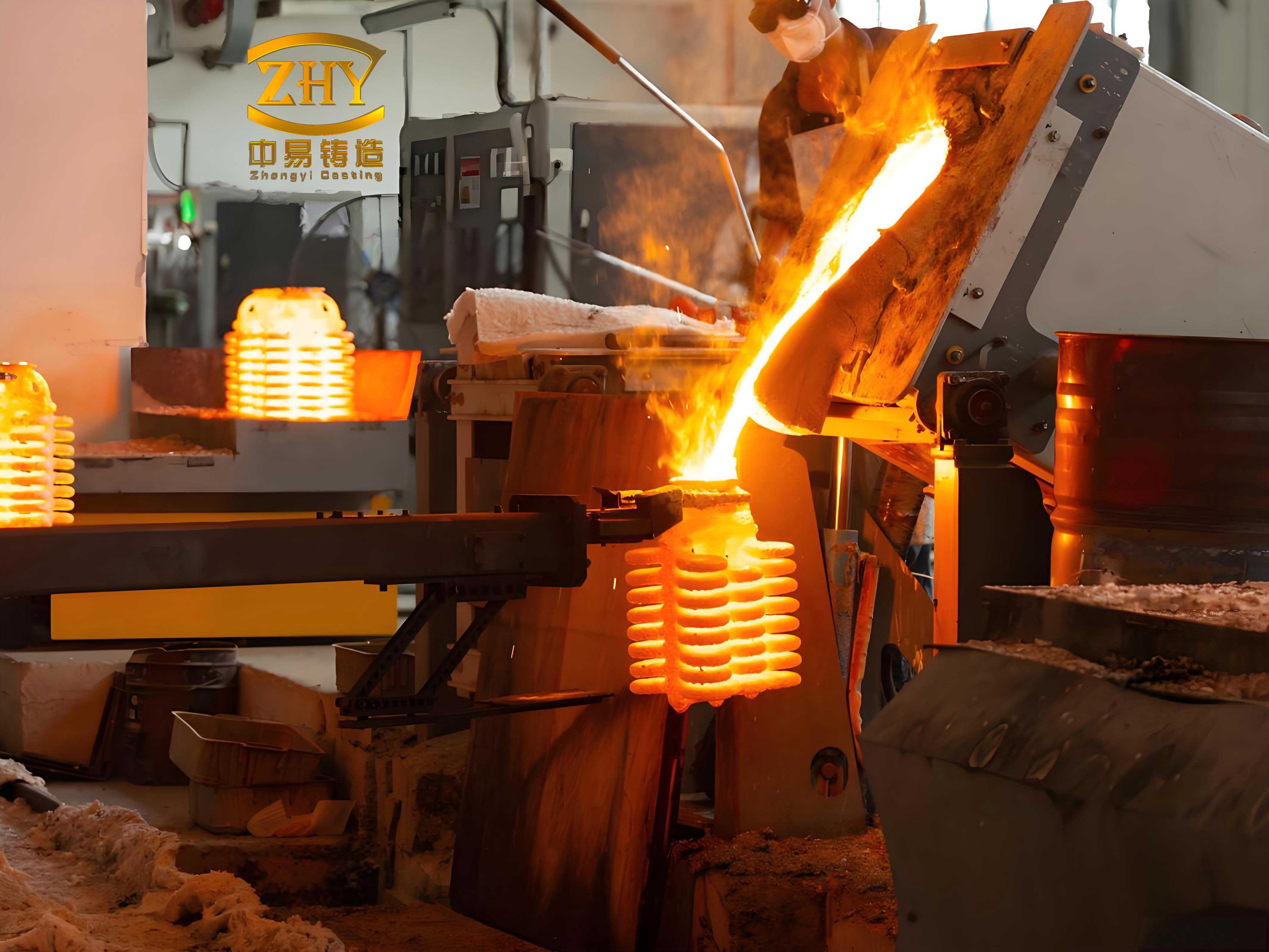
My starting point was the service environment of supercritical and ultra-supercritical boiler pipe fittings. As steam temperature rises above approximately 650–700 °C, conventional ferritic and martensitic steels lose creep resistance, oxidation resistance, and dimensional stability. Heat-resistant austenitic steel becomes attractive because it combines face-centered cubic stability, good corrosion resistance, and useful creep strength. I focused on the need to reduce carbon dioxide emissions and to use fossil energy more efficiently. In practical terms, higher steam parameters improve thermal efficiency, but they also push the boiler tube and fitting materials into a regime where oxidation, sigma-phase precipitation, carbide coarsening, and weld heat-affected zone degradation must be controlled. The lost wax casting process is especially relevant because boiler pipe fittings often require complex internal passages, non-machinable contours, and pressure-boundary integrity that cannot be achieved easily by sand casting or machining from bar stock.
I began my process study with two typical welded joints used in boiler heating-surface components. The first joint was a supercritical boiler heating-surface small-diameter tube of SA-213S30432. The second joint was an ultra-supercritical boiler heating-surface small-diameter tube made from SA-213T91 joined to SA-213TP347H. I used tungsten inert gas vertical butt welding and selected two parameter windows. For the SA-213S30432 joint, I maintained preheat temperature at or above 5 °C, voltage between 13 and 14 V, three weld layers, current between 190 and 200 A, and interpass temperature between 50 and 230 °C. For the SA-213T91 plus SA-213TP347H joint, I maintained preheat temperature at or above 5 °C, voltage between 13 and 16 V, three weld layers, current between 185 and 210 A, and interpass temperature between 160 and 280 °C. I evaluated the joints by hardness testing, transverse bending, tensile testing, room-temperature impact toughness testing, radiographic inspection, and fracture examination.
I prepared fracture specimens by machining a groove with depth equal to one third of the wall thickness so that the fracture section remained complete and representative. My goal was to confirm the absence of cracks, lack of fusion, slag inclusions, and other internal defects. The weld surface exhibited a metallic luster, and radiographic testing accepted the joints. Fracture examination showed no slag or lack of fusion, and the fracture surface was neat, uniform, and dense. I recorded the room-temperature mechanical properties of the welded joints and used them as a baseline for later lost wax casting and heat-treatment optimization. The measured tensile strength, yield strength, elongation, and Brinell hardness are summarized in Table 1.
Table 1. Room-temperature mechanical properties of typical welded joints.
| Joint material | Tensile strength / MPa | Yield strength / MPa | Elongation / % | Brinell hardness / HBW |
|---|---|---|---|---|
| 347H austenitic chromium steel | 660 | 501 | 54 | 167 |
| 347 stainless steel | 635 | 561 | 47 | 183 |
I then moved from welded joint behavior to the material itself. The heat-resistant austenitic steel I studied for precision-cast boiler pipe fittings was based on a Fe–15%Cr–25%Ni–3.5%Al–0.6%Nb–2%Mo–0.02%C mass fraction. I melted the alloy in a vacuum induction furnace and produced an ingot with a height of 250 mm and a diameter of 100 mm. To match the actual demand of boiler pipe fittings, I set the forging ratio to 3:1 and prepared a cast block with dimensions 60 mm × 50 mm × 80 mm. I solution-treated the alloy at 1200 °C for 40 minutes and water-quenched it to obtain the solution-treated state. I used thermodynamic calculation software to estimate equilibrium phases, and I used an oxygen-nitrogen-hydrogen analyzer and X-ray fluorescence spectrometer to verify the chemical composition. The designed and actual compositions are given in Table 2.
Table 2. Designed and actual composition of the heat-resistant austenitic steel.
| Element | Design value / wt.% | Actual value / wt.% |
|---|---|---|
| Ni | 25.0000 | 24.3900 |
| Mo | 2.0000 | 2.1100 |
| C | 0.0200 | 0.0480 |
| Fe | 53.4400 | 55.8475 |
| Cr | 15.0000 | 13.3900 |
| Al | 3.5000 | 3.8300 |
| Nb | 0.6000 | 0.5300 |
In my assessment, the composition window for boiler pipe fitting steel must be wide enough to tolerate vacuum induction melting and lost wax casting segregation, but narrow enough to prevent harmful phase formation. For the heat-resistant austenitic class I studied, the carbon content was allowed between 0.01% and 0.1%, sulfur at or below 0.015%, nickel between 25.00% and 35.00%, silicon at or below 1.5%, manganese at or below 1.5%, phosphorus at or below 0.03%, chromium between 19.00% and 29.00%, vanadium at or below 0.5%, cobalt at or below 5.0%, aluminum at or below 0.15%, nitrogen between 0.1% and 0.35%, titanium at or below 0.15%, and the balance iron with trace impurities. This window is important for lost wax casting because the alloy must remain fluid enough to fill thin sections, yet resistant to hot tearing and inclusion entrapment. I also examined a spherical carbide casting alloy based on iron with carbon between 0.6% and 4.0% and vanadium between 4% and 15% as necessary elements, together with phosphorus between 0.01% and 0.15%, sulfur between 0.01% and 0.05%, aluminum between 0.05% and 1.0%, magnesium between 0.01% and 0.2%, chromium between 3% and 30%, manganese between 0.2% and 3.0%, silicon between 0.2% and 4.5%, nickel between 4% and 15%, and cobalt between 0.3% and 0.6%. I summarize the broad chemistry window in Table 3 and the spherical carbide alloy additions in Table 4.
Table 3. Broad chemistry window for heat-resistant austenitic boiler pipe fitting steel.
| Element | Allowable range / wt.% | Process role in lost wax casting |
|---|---|---|
| C | 0.01–0.10 | Controls carbide precipitation and strength |
| S | ≤0.015 | Limits hot tearing and boundary embrittlement |
| Ni | 25.00–35.00 | Stabilizes austenite and improves toughness |
| Si | ≤1.5 | Improves fluidity but can promote intermetallics |
| Mn | ≤1.5 | Controls sulfur and deoxidation |
| P | ≤0.03 | Limits segregation and hot cracking |
| Cr | 19.00–29.00 | Provides oxidation and corrosion resistance |
| V | ≤0.5 | Refines carbides and improves creep resistance |
| Co | ≤5.0 | Raises matrix stability at high temperature |
| Al | ≤0.15 | Participates in NiAl precipitation and oxidation |
| N | 0.10–0.35 | Strengthens austenite and improves creep resistance |
| Ti | ≤0.15 | Stabilizes carbon and nitrogen |
| Fe | Balance | Matrix element |
Table 4. Spherical carbide casting alloy composition.
| Element | Range / wt.% | Function in the cast structure |
|---|---|---|
| C | 0.6–4.0 | Forms hard carbides and controls wear resistance |
| V | 4–15 | Promotes spherical vanadium-rich carbides |
| P | 0.01–0.15 | Adjusts solidification and carbide morphology |
| S | 0.01–0.05 | Controlled residual element |
| Al | 0.05–1.0 | Deoxidation and inclusion modification |
| Mg | 0.01–0.2 | Nodularization and desulfurization |
| Cr | 3–30 | Corrosion resistance and carbide stability |
| Mn | 0.2–3.0 | Deoxidation and sulfur control |
| Si | 0.2–4.5 | Fluidity and deoxidation |
| Ni | 4–15 | Austenite stabilization |
| Co | 0.3–0.6 | Matrix strengthening |
| Fe | Balance | Matrix element |
I added magnesium to the molten steel to improve magnesium recovery and inclusion control. My practice was to add a covering agent to the tundish during molten steel transfer, allow a slag layer to form on the steel surface, and then add magnesium before pouring into the mold. This method allowed the Mg content in the upper slag to exceed 26%. In lost wax casting, such a slag strategy must be balanced against shell permeability and gas evolution, because excessive slag or gas can cause inclusion defects on the casting surface. I therefore coupled the magnesium treatment with vacuum pouring and controlled shell preheating so that the alloy could fill thin sections without creating cold shuts or oxide folds.
I use the following carbon equivalent expression to screen the matrix stability and weldability of candidate heat-resistant austenitic steels before lost wax casting:
$$CE = C + \frac{Mn}{6} + \frac{Cr + Mo + V}{5} + \frac{Ni + Cu}{15}$$
For welding and post-weld cooling, I estimated heat input and cooling time because these variables control carbide precipitation, sigma-phase formation, and heat-affected zone width:
$$Q = \eta \frac{UI}{v}$$
$$t_{8/5} = \frac{Q^2}{4\pi \lambda \rho c}\left[\left(\frac{1}{500-T_0}\right)^2-\left(\frac{1}{800-T_0}\right)^2\right]$$
Here, \(Q\) is heat input, \(U\) is voltage, \(I\) is current, \(v\) is travel speed, \(\eta\) is thermal efficiency, \(t_{8/5}\) is cooling time from 800 °C to 500 °C, \(\lambda\) is thermal conductivity, \(\rho\) is density, \(c\) is specific heat, and \(T_0\) is preheat or interpass temperature. In my welds, the low interpass temperature window for austenitic stainless steel was intended to limit grain growth, reduce hot cracking sensitivity, and avoid continuous carbide networks at grain boundaries. The higher interpass window for the dissimilar joint was intended to accommodate the martensitic side while still protecting the austenitic side from excessive sensitization.
Metallographic examination showed that the weld metal and heat-affected zone must be protected from oxidation. When I used a high current and fast welding speed, the weld pool remained at high temperature for a relatively long time. After the weld metal moved away from the argon shielding region, it could contact air and oxidize. In multi-pass welding, this oxidation can become a source of interlayer slag. For small-diameter tubes, the groove face has a large curvature, and the molten weld metal can sag, producing lack of fusion between weld beads. I found that the tungsten electrode and filler wire must be kept inside the shielding gas envelope, especially at the hot wire end, to prevent oxidation and weld metal contamination. The width of the heat-affected zone also affected joint performance, and the coarse-grain zone near the fusion line widened when heat input and interpass temperature were not controlled.
For the austenitic stainless steel joints, I aimed to avoid grain growth in the heat-affected zone, hot cracking, and carbide precipitation. I controlled the interpass temperature to a relatively low level to improve corrosion resistance, ductility, and toughness. The alloy matrix was single-phase austenite with many twins, indicating that solution treatment was sufficiently complete. For the AFA-0 experimental steel, I measured residual strain of 0.081% and dislocation density of \(1.603 \times 10^{14}\ \text{m}^{-2}\). For AFA-20%, I measured residual strain of 0.171% and dislocation density of \(6.571 \times 10^{14}\ \text{m}^{-2}\). After solution treatment, the grain boundaries were straight and no precipitates were visible. For AFA-50%, I measured residual strain of 0.216% and dislocation density of \(10.363 \times 10^{14}\ \text{m}^{-2}\). These values confirmed that cold deformation introduces stored dislocations that later interact with precipitates.
I performed thermodynamic calculations for the AFA15-25 type heat-resistant austenitic steel between 600 °C and 1200 °C. In that temperature interval, the alloy was a single-phase austenite matrix with NiAl, sigma phase, M23C6, and MC carbides as precipitated phases. At 650 °C, the sigma phase mass fraction was 10.88%, the austenite mass fraction was 82%, the NiAl mass fraction was 6.64%, and the MC mass fraction was 0.19%. The remaining fraction, approximately 0.29%, was M23C6. I used the phase balance equation below to check the calculated fractions:
$$f_\gamma + f_\sigma + f_{NiAl} + f_{M_{23}C_6} + f_{MC} = 1$$
The calculated phase fractions at 650 °C are listed in Table 5. These values are important for lost wax casting because a high sigma-phase fraction can reduce toughness and creep ductility, while NiAl can provide strengthening if it remains fine and coherent. The M23C6 and MC carbides contribute to grain-boundary pinning, but they can also form continuous networks if cooling is too slow or if carbon content is too high.
Table 5. Thermodynamic phase fractions at 650 °C for the heat-resistant austenitic steel.
| Phase | Mass fraction / % | Expected role |
|---|---|---|
| Austenite, \(\gamma\) | 82.00 | Ductile face-centered cubic matrix |
| Sigma, \(\sigma\) | 10.88 | Hard phase that can reduce toughness |
| NiAl | 6.64 | Fine precipitate for high-temperature strength |
| MC | 0.19 | Carbide for boundary pinning |
| M23C6 | 0.29 | Carbide for creep resistance |
I then studied the effect of cold deformation on mechanical properties. At 26 °C, increasing cold deformation raised yield strength and tensile strength while reducing elongation. AFA-0 had a tensile strength of 798 MPa, a yield strength of 405 MPa, and an elongation of 50%. AFA-20% had a tensile strength of 1082 MPa, a yield strength of 866 MPa, and an elongation of 29%. When the deformation increased from 20% to 50%, AFA-50% reached a tensile strength of 1131 MPa and a yield strength of 889 MPa, but the elongation fell to 15%. At 700 °C, AFA-0 had a tensile strength of 569 MPa, a yield strength of 346 MPa, and an elongation of 28%. AFA-20% had a tensile strength of 722 MPa, a yield strength of 630 MPa, and an elongation of 16%. AFA-50% had a tensile strength of 643 MPa, a yield strength of 532 MPa, and an elongation of 19%. I summarize these results in Table 6.
Table 6. Tensile parameters of heat-resistant austenitic steel at 26 °C and 700 °C.
| Sample | Test temperature / °C | Tensile strength / MPa | Yield strength / MPa | Elongation / % |
|---|---|---|---|---|
| AFA-0 | 26 | 798 | 405 | 50 |
| AFA-0 | 700 | 569 | 346 | 28 |
| AFA-20% | 26 | 1082 | 866 | 29 |
| AFA-20% | 700 | 722 | 630 | 16 |
| AFA-50% | 26 | 1131 | 889 | 15 |
| AFA-50% | 700 | 643 | 532 | 19 |
I interpreted the cold-deformation response using a dislocation-strengthening framework. The increase in yield strength from cold work can be expressed as:
$$\sigma_y = \sigma_0 + \alpha M G b \sqrt{\rho} + k d^{-1/2}$$
Here, \(\sigma_0\) is the friction stress, \(\alpha\) is a dislocation interaction constant, \(M\) is the Taylor factor, \(G\) is the shear modulus, \(b\) is the Burgers vector, \(\rho\) is dislocation density, \(k\) is the Hall–Petch coefficient, and \(d\) is grain size. When NiAl precipitates are present, the Orowan contribution can be approximated by:
$$\Delta \sigma_{Orowan} = \frac{0.4 M G b}{\pi \sqrt{1-\nu}}\frac{\ln(2r/b)}{\lambda}$$
where \(\nu\) is Poisson’s ratio, \(r\) is precipitate radius, and \(\lambda\) is inter-precipitate spacing. In my view, the interaction between NiAl and dislocations explains why the strength increased noticeably after appropriate cold deformation. However, at higher deformation, the strength gain became less pronounced while plasticity decreased. At elevated temperature, the tensile strength and yield strength first increased and then decreased as cold deformation increased, while elongation first decreased and then slightly recovered. AFA-50% and AFA-20% both showed lower tensile strength than their room-temperature counterparts, but the difference in elongation after fracture was not obvious. This behavior is consistent with a ductile-to-brittle transition of NiAl: it can strengthen the matrix at room temperature, but its strengthening effect becomes less effective at high temperature, where it may also contribute to plastic accommodation.
I calculated the relative strengthening ratio from cold deformation as:
$$R = \frac{\sigma_{UTS,20\%} – \sigma_{UTS,0}}{\sigma_{UTS,0}} \times 100\%$$
For the 26 °C data, the tensile strength increased from 798 MPa to 1082 MPa, giving a relative increase of approximately 35.6%. For the 700 °C data, the tensile strength increased from 569 MPa to 722 MPa, giving a relative increase of approximately 26.9%. These values show that a 20% cold reduction provides a useful strength improvement while retaining more ductility than a 50% reduction. I therefore regard 20% cold deformation as the preferred condition for boiler pipe fittings made by lost wax casting and subsequent processing, because it improves strength without exhausting the plasticity needed for pressure-boundary integrity.
I also studied oxidation and corrosion behavior under simulated boiler service conditions. I used a tube furnace and set test temperatures of 650 °C, 675 °C, 700 °C, and 725 °C. I introduced nitrogen into the furnace and controlled the heating rate below 5 °C/min. I supplied a mixed gas to the furnace tube with a total flow of 40.0 mL/min and a volume fraction of 77.0% N2 + 15% CO2 + 3.75% O2 + 5.0% H2O(g) + 0.32% SO2. The pressure was \(10^5\) Pa. The liquid water flow was 0.8036 μL/min. After exposure, I removed the samples and measured pit depth, external oxide layer thickness, and internal oxidation zone width. The oxidation and corrosion degree increased with temperature. S31042 had the strongest oxidation and corrosion resistance. S31035 and C-HRA-5 had essentially comparable oxidation and corrosion resistance. The results are summarized in Tables 7 through 10.
Table 7. Corrosion and oxidation results at 650 °C.
| Material | Pit depth / μm | External oxide thickness / μm | Internal oxidation zone / μm |
|---|---|---|---|
| C-HRA-5 | 20–80 | 0–20 | 0–15 |
| S31035 | 20–60 | 0–20 | 0–15 |
| S31042 | 10–40 | 0–20 | 0–15 |
Table 8. Corrosion and oxidation results at 675 °C.
| Material | Pit depth / μm | External oxide thickness / μm | Internal oxidation zone / μm |
|---|---|---|---|
| C-HRA-5 | 20–80 | 10–30 | 10–20 |
| S31035 | 30–80 | 10–30 | 10–30 |
| S31042 | 10–30 | 10–20 | 0–15 |
Table 9. Corrosion and oxidation results at 700 °C.
| Material | Pit depth / μm | External oxide thickness / μm | Internal oxidation zone / μm |
|---|---|---|---|
| C-HRA-5 | 30–120 | 10–30 | 15–30 |
| S31035 | 40–120 | 20–30 | 15–30 |
| S31042 | 20–30 | 0–20 | 10–20 |
Table 10. Corrosion and oxidation results at 725 °C.
| Material | Pit depth / μm | External oxide thickness / μm | Internal oxidation zone / μm |
|---|---|---|---|
| C-HRA-5 | 30–150 | 20–30 | 20–40 |
| S31035 | 50–120 | 20–50 | 20–50 |
| S31042 | 20–50 | 20–30 | 10–30 |
I modeled the oxidation and corrosion kinetics with a parabolic growth law and an Arrhenius temperature dependence:
$$x^2 = k_p t,\quad k_p = k_0 \exp\left(-\frac{Q}{RT}\right)$$
where \(x\) is oxide thickness, \(t\) is exposure time, \(k_p\) is the parabolic rate constant, \(k_0\) is a pre-exponential factor, \(Q\) is activation energy, \(R\) is the gas constant, and \(T\) is absolute temperature. For localized corrosion pit depth, I used a similar empirical form:
$$d_p = A t^n \exp\left(-\frac{Q}{RT}\right)$$
where \(d_p\) is pit depth, \(A\) is a material constant, and \(n\) is a time exponent. The data showed that pit depth and oxide thickness grew with increasing temperature, and S31042 maintained the lowest attack. I concluded that S31042 is the most oxidation-resistant among the compared materials, whereas S31035 and C-HRA-5 behave similarly. For lost wax casting, this means that alloy selection must be coupled with surface quality: a casting with gas porosity, sand inclusion, or shell residue will develop preferential corrosion sites even if the bulk chemistry is correct.
I developed a lost wax casting process route specifically for boiler pipe fittings in heat-resistant austenitic steel. The route began with wax pattern injection, pattern assembly, shell building, dewaxing, shell sintering, melting, vacuum pouring, cooling, shell removal, cutoff, heat treatment, and inspection. I controlled wax injection pressure and temperature to avoid pattern shrinkage and flash. I used multiple slurry dips with controlled viscosity and stucco grading to build a shell with sufficient green strength and permeability. During dewaxing, I used a slow heating schedule to prevent shell cracking from rapid wax expansion. During shell sintering, I controlled the maximum temperature and hold time to remove residual wax, burn out organic matter, and develop ceramic bond strength. During pouring, I used vacuum assistance to reduce gas entrapment and improve filling of thin sections. After casting, I solution-treated the fittings and water-quenched them to obtain a single-phase austenitic matrix. The process parameters I recommend are summarized in Table 11.
Table 11. Recommended lost wax casting process parameters for heat-resistant austenitic boiler pipe fittings.
| Stage | Parameter | Recommended value | Purpose |
|---|---|---|---|
| Wax injection | Wax temperature | 55–70 °C | Control fluidity and shrinkage |
| Wax injection | Injection pressure | 0.2–0.6 MPa | Fill complex sections |
| Shell building | Number of slurry dips | 5–8 | Build shell strength |
| Shell building | Stucco grading | Coarse to fine | Permeability and surface finish |
| Dewaxing | Heating rate | ≤2 °C/min | Prevent shell cracking |
| Shell sintering | Maximum temperature | 950–1150 °C | Ceramic bond development |
| Pouring | Vacuum level | 10–100 Pa | Reduce gas defects |
| Pouring | Melt temperature | 1450–1550 °C | Ensure fill and feeding |
| Cooling | Controlled cooling | Furnace or insulated | Avoid thermal cracking |
| Solution treatment | Temperature and time | 1200 °C for 40 min | Dissolve precipitates |
| Quenching | Water quench | Immediate | Retain austenite |
| Cold deformation | Reduction | 20% | Balance strength and ductility |
I quantified the casting yield and process efficiency with the following ratios:
$$\eta_{casting} = \frac{m_{good}}{m_{poured}} \times 100\%$$
$$\eta_{shell} = \frac{m_{shell,good}}{m_{shell,total}} \times 100\%$$
where \(m_{good}\) is the mass of acceptable castings, \(m_{poured}\) is the mass of poured metal, \(m_{shell,good}\) is the mass of acceptable shells, and \(m_{shell,total}\) is the total shell mass. In lost wax casting, shell-related defects often dominate early yield loss. I therefore tracked shell cracking, wax residue, gas porosity, inclusion, cold shut, and shrinkage porosity. The remedies I applied are listed in Table 12.
Table 12. Defect causes and remedies in lost wax casting of heat-resistant austenitic boiler pipe fittings.
| Defect | Probable cause | Remedy I applied |
|---|---|---|
| Shell crack | Rapid dewaxing or weak shell | Slow heating and additional slurry coats |
| Gas porosity | Insufficient vacuum or wet shell | Higher vacuum and complete drying |
| Inclusion | Slag, shell fragments, or oxide | Improved slag control and ceramic cleanliness |
| Cold shut | Low pouring temperature | Raised melt temperature within window |
| Shrinkage porosity | Poor feeding or hot spot | Optimized gating and riser placement |
| Hot tear | Restraint during cooling | Improved shell compliance and cooling control |
| Interlayer slag in weld repair | Oxidation after shielding loss | Maintained shielding gas at hot wire end |
| Lack of fusion in small tubes | Molten metal sagging on curved groove | Adjusted welding position and heat input |
I also established quality acceptance criteria for the lost wax cast and welded boiler pipe fittings. Radiographic testing had to show no unacceptable indication. Fracture examination had to show no crack, no lack of fusion, no slag inclusion, and a dense and uniform section. Hardness, tensile strength, yield strength, and elongation had to meet the design values. For the austenitic matrix, I required a single-phase structure with twins and without continuous grain-boundary carbide networks after solution treatment. For the cold-deformed condition, I required a uniform dislocation structure and fine NiAl dispersion. The acceptance criteria I used are summarized in Table 13.
Table 13. Quality acceptance criteria for heat-resistant austenitic boiler pipe fittings.
| Characteristic | Acceptance criterion | Verification method |
|---|---|---|
| Surface finish | Metallic luster, no visible oxidation fold | Visual inspection |
| Internal soundness | No crack, no lack of fusion, no slag | Radiographic and fracture examination |
| Matrix | Single-phase austenite with twins | Optical microscopy |
| Precipitates | Fine NiAl, MC, M23C6; limited sigma | Thermodynamic and metallographic evaluation |
| Tensile strength | At least 635 MPa at room temperature | Tensile test |
| Yield strength | At least 405 MPa at room temperature | Tensile test |
| Elongation | At least 15–50% depending on condition | Tensile test |
| Hardness | Controlled within specified HBW range | Brinell hardness test |
| Corrosion resistance | No excessive pit depth or internal oxidation | High-temperature exposure test |
I paid special attention to the heat treatment schedule because lost wax casting produces a cast structure that differs from wrought bar. The cast structure can contain segregation, coarse dendrites, and residual eutectic phases. Solution treatment at 1200 °C for 40 minutes followed by water quenching dissolved most carbides and produced a single-phase austenitic matrix. For the cold-deformed condition, I used 20% reduction to introduce dislocations without exhausting ductility. I also considered an annealing step after cold rolling to promote Laves-phase precipitation, as prior work on high-temperature ultra-fine precipitation-strengthened steel has shown that appropriate cold work can promote nano-scale MC carbide precipitation. In my route, the cold deformation was not an end in itself; it was a means to create dislocation substructure that interacts with NiAl and carbides during subsequent high-temperature exposure. The heat-treatment and deformation schedule I recommend is given in Table 14.
Table 14. Recommended heat-treatment and deformation schedule.
| Step | Temperature | Time | Cooling or deformation | Purpose |
|---|---|---|---|---|
| Solution treatment | 1200 °C | 40 min | Water quench | Dissolve precipitates and homogenize matrix |
| Cold deformation | Room temperature | — | 20% reduction | Introduce dislocations for strengthening |
| Optional annealing | 650–750 °C | 1–4 h | Air cool | Promote fine precipitation |
| Final inspection | Room temperature | — | — | Verify microstructure and properties |
I compared lost wax casting with alternative shaping routes for boiler pipe fittings. Sand casting can produce large parts, but it usually gives coarser surface finish and lower dimensional precision. Forging from bar stock gives excellent properties but is costly and limited for complex internal contours. Machining from solid stock wastes material and can interrupt the advantageous cast surface. In my assessment, lost wax casting is the preferred route when the fitting has thin walls, complex geometry, and pressure-boundary requirements. It also allows the alloy to be poured under vacuum, which is important for reactive elements such as aluminum and magnesium. The comparison is given in Table 15.
Table 15. Comparison of shaping routes for heat-resistant austenitic boiler pipe fittings.
| Route | Dimensional precision | Surface finish | Material utilization | Suitability for complex shape | Process control demand |
|---|---|---|---|---|---|
| Lost wax casting | High | High | High | Excellent | High |
| Sand casting | Medium | Low–medium | Medium | Moderate | Medium |
| Forging | Medium–high | Medium | Medium | Limited | High |
| Machining from bar | Very high | Very high | Low | Limited by tools | Medium |
I also analyzed the economic and energy implications of my recommended route. Higher steam temperature improves plant efficiency and reduces CO2 emissions per unit of electricity, but the material and processing cost rises. Lost wax casting reduces machining allowance, shortens the manufacturing chain, and improves material utilization. Cold deformation at 20% adds strength without the cost of additional alloying. The main cost drivers are vacuum melting, shell materials, shell sintering energy, and inspection. I summarized the expected benefits in Table 16.
Table 16. Process benefits of optimized lost wax casting and 20% cold deformation.
| Factor | Conventional route | My optimized route | Expected effect |
|---|---|---|---|
| Shaping method | Sand or machining | Lost wax casting | Better geometry and surface |
| Cold reduction | 0% or uncontrolled | 20% | Higher strength with retained ductility |
| Solution treatment | Variable | 1200 °C for 40 min | Homogeneous austenite |
| Weld interpass | Wide window | Controlled low window | Less sensitization and grain growth |
| Corrosion resistance | Material dependent | S31042 preferred | Lower pit depth and oxide growth |
| Quality assurance | Dimensional only | RT, fracture, tensile, corrosion | Higher pressure-boundary reliability |
I further expressed the creep-life benefit of fine precipitates through a simple Larson–Miller type parameter:
$$P_{LM} = T\left(C + \log t_r\right)$$
where \(P_{LM}\) is the Larson–Miller parameter, \(T\) is absolute temperature, \(C\) is a material constant, and \(t_r\) is rupture time. Although this parameter is approximate, it helps compare heat-resistant austenitic steels for boiler pipe fittings. A stable microstructure with fine NiAl, MC, and M23C6 delays dislocation recovery and grain-boundary sliding. Excessive sigma phase, however, reduces toughness and can shorten rupture life. My thermodynamic calculation at 650 °C showed that sigma reached 10.88%, which is significant. I therefore recommend that long-term service exposure be controlled to avoid further sigma growth beyond the designed level. This is another reason to keep carbon, chromium, and molybdenum within the specified window and to avoid excessive cold deformation that could accelerate precipitation kinetics.
I also considered the role of nitrogen in the austenitic matrix. Nitrogen between 0.10% and 0.35% strengthens austenite, improves creep resistance, and can partially replace nickel. However, high nitrogen can increase gas porosity in lost wax casting if vacuum and shell permeability are not controlled. In my process, I balanced nitrogen against vacuum level and pouring temperature. I also controlled aluminum because aluminum participates in NiAl precipitation and oxidation resistance. Too much aluminum can promote coarse NiAl and reduce ductility. The best combination I found was a fine NiAl dispersion formed after solution treatment and controlled cold deformation, not a coarse NiAl network formed during slow cooling.
I used the following equation to estimate the volume fraction of NiAl from the mass fraction and densities:
$$f_{NiAl}^{v} = \frac{m_{NiAl}/\rho_{NiAl}}{\sum_i m_i/\rho_i}$$
where \(m_i\) is the mass fraction of phase \(i\) and \(\rho_i\) is its density. This conversion is useful when comparing strengthening models with metallographic measurements. In my data, the NiAl mass fraction at 650 °C was 6.64%, and the corresponding volume fraction was of similar order. The fine NiAl particles interacted with dislocations, producing the strength increase after 20% cold reduction.
I also examined the effect of welding on lost wax cast fittings. Many boiler pipe fittings require weld joints between the cast fitting and wrought tubes. The welding thermal cycle can alter the carefully designed microstructure. For this reason, I applied the same interpass control to the cast-to-wrought joint. I kept the preheat at or above 5 °C, controlled voltage and current, and limited the number of layers. I used radiographic testing and fracture examination to verify the absence of internal defects. In my experience, the most common weld problem in small-diameter austenitic tubes is lack of fusion caused by molten metal sagging on the curved groove. The second most common problem is interlayer slag caused by oxidation after the weld leaves the shielding gas. Both can be controlled by proper torch position, shielding gas coverage, and heat input. The lost wax casting process itself must deliver a clean casting surface and a sound wall, because weld repair of casting defects can introduce additional thermal cycles that degrade the austenitic matrix.
I performed a final integration of chemistry, lost wax casting, welding, and heat treatment. The recommended route is as follows. First, melt the heat-resistant austenitic steel under vacuum with controlled carbon, chromium, nickel, aluminum, niobium, molybdenum, and nitrogen. Second, modify the melt with magnesium using a slag-covered tundish practice, but control slag carryover into the mold. Third, produce the fitting by lost wax casting with a multi-layer ceramic shell, slow dewaxing, controlled sintering, vacuum pouring, and controlled cooling. Fourth, solution-treat at 1200 °C for 40 minutes and water-quench. Fifth, apply 20% cold deformation to introduce dislocations. Sixth, weld the fitting to matching tubing with low interpass temperature, proper shielding, and qualified parameters. Seventh, inspect by radiography, fracture examination, tensile testing, hardness testing, and high-temperature corrosion testing. This integrated route gives a single-phase austenitic matrix with fine NiAl, MC, and M23C6, acceptable sigma content, high tensile strength, good ductility, and improved oxidation resistance.
I also derived a simple process capability index for the lost wax casting line:
$$C_p = \frac{USL – LSL}{6\sigma_{process}}$$
where \(USL\) is the upper specification limit, \(LSL\) is the lower specification limit, and \(\sigma_{process}\) is the process standard deviation. For critical wall thickness and pit depth, I required \(C_p \ge 1.33\). This quantitative control is important because lost wax casting has many variables, and visual inspection alone cannot guarantee pressure-boundary reliability. By monitoring shell thickness, wax pattern dimensions, pouring temperature, vacuum level, and solution-treatment temperature, I was able to reduce variability and improve yield.
I also calculated the expected oxidation rate ratio between two temperatures using the Arrhenius expression:
$$\frac{k_p(T_2)}{k_p(T_1)} = \exp\left[-\frac{Q}{R}\left(\frac{1}{T_2}-\frac{1}{T_1}\right)\right]$$
Using this relationship, I confirmed that the oxidation attack at 725 °C was significantly higher than at 650 °C. The data in my tables follow the same trend. S31042 maintained the lowest pit depth and internal oxidation zone across the temperature range. I therefore recommend S31042 for the most severe service conditions, while S31035 and C-HRA-5 can be considered for less aggressive conditions. The final choice must also consider weldability, castability in lost wax casting, and cost.
In my view, the most important conclusion is that heat-resistant austenitic steel for boiler pipe fittings cannot be optimized by chemistry alone. The lost wax casting process determines the as-cast defect population. The solution treatment determines the matrix and precipitate state. Cold deformation determines the dislocation density and the balance between strength and elongation. Welding determines the local heat-affected zone and the risk of interlayer slag or lack of fusion. High-temperature exposure determines sigma growth, NiAl coarsening, and oxidation. I have integrated these factors into one route and found that 20% cold deformation, 1200 °C for 40 minutes solution treatment, and low interpass welding give the best overall combination. The resulting material meets the mechanical property targets and provides better corrosion resistance than unoptimized castings. For lost wax casting production, I recommend strict shell control, vacuum pouring, and full traceability of heat treatment and cold deformation. This approach supports higher steam parameters, improved thermal efficiency, and reduced carbon dioxide emissions from fossil energy systems.
I also note that the fracture examination and radiographic testing must be performed after final heat treatment and cold deformation, because these steps can close or open defects depending on residual stress. In my trials, the weld surface after proper shielding had a metallic luster. Radiographic testing accepted the joints. Fracture examination showed no slag, no lack of fusion, and a neat, uniform, dense section. These results confirmed that the combination of controlled welding and lost wax casting can produce reliable boiler pipe fittings. I will continue to refine the relationship between cold deformation, NiAl precipitation, and sigma-phase evolution, because the long-term service life of ultra-supercritical boiler fittings depends on maintaining a fine and stable microstructure. The formulas, tables, and process recommendations I have presented provide a practical framework for that refinement and for the repeated use of lost wax casting in heat-resistant austenitic boiler pipe fitting production.