
In my research and engineering practice, I have repeatedly observed that precision casting, especially investment casting used for aerospace and energy equipment, depends to a remarkable degree on the behavior of the ceramic shell. The shell is not a passive container. It is an active thermomechanical system that must survive dewaxing, high-temperature sintering, metal pouring, and solidification. Whenever the thermal stress inside that system exceeds the strength of the ceramic, the shell cracks, deforms, or loses dimensional stability, and the resulting defects are transferred directly to the casting. Therefore, in this review I systematically examine the formation mechanism of thermal stress in ceramic shells for precision casting, summarize the influencing factors, and evaluate material optimization, process control, structural design, and intelligent control strategies. I also present industrial data showing that an integrated approach can reduce shell thermal stress by more than 30%, raise the yield of critical castings from approximately 72% to above 95%, and improve dimensional accuracy to the CT7 grade.
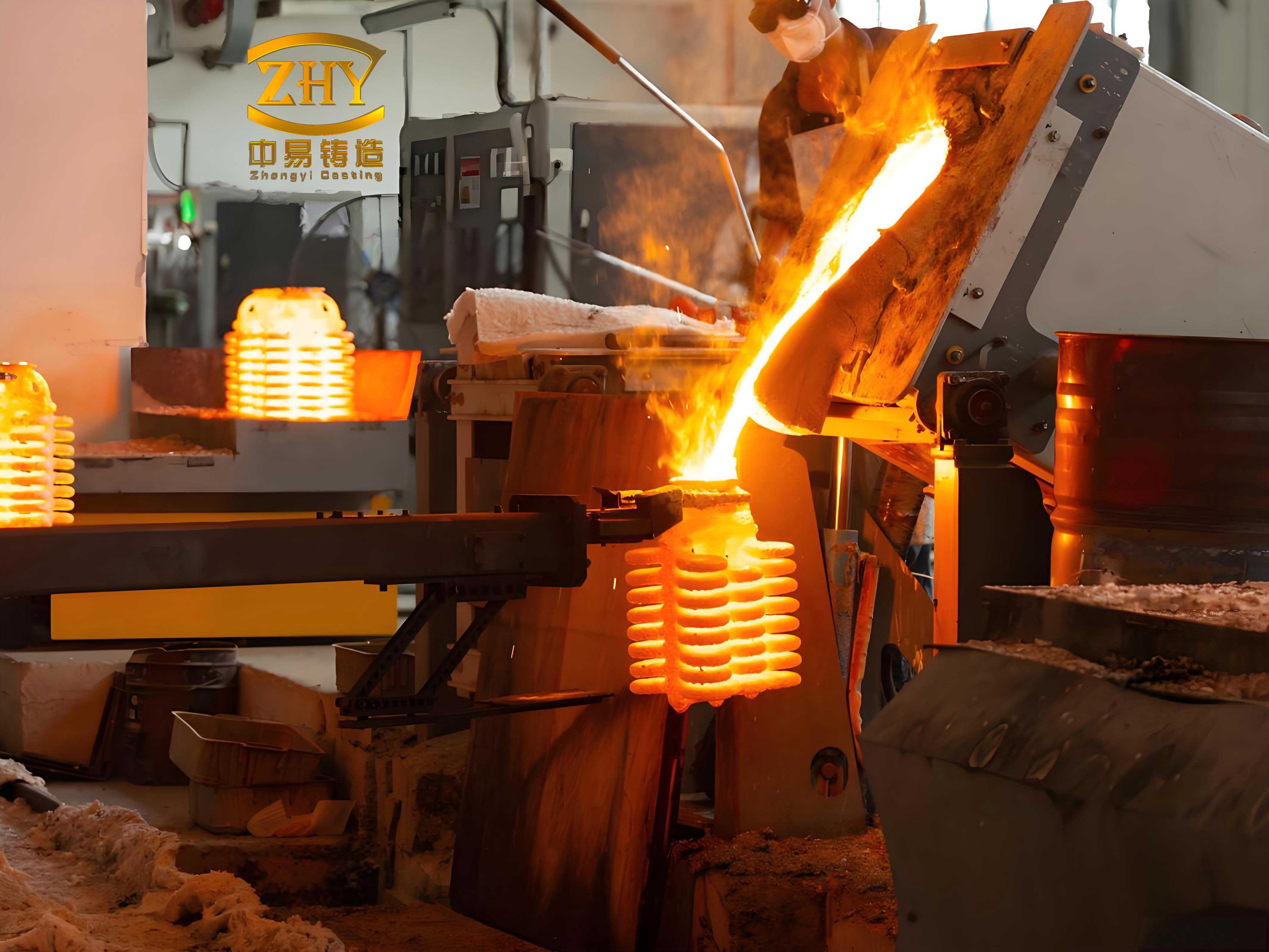
From my perspective, the central challenge of precision casting is not merely achieving a good cavity geometry. It is achieving a cavity that remains geometrically and mechanically stable under severe transient thermal loading. In the following sections I describe how I analyze that challenge, how I quantify it, and how I translate the analysis into practical shell design and process control.
1. Why Thermal Stress Dominates Shell Failure in Precision Casting
In precision casting, the ceramic shell experiences a sequence of thermal cycles that are far from uniform. During dewaxing, the pattern expands, the shell is heated unevenly, and the outer surface may remain much cooler than the inner surface. During sintering, organic matter decomposes and gases escape while the ceramic network densifies. During pouring, molten metal at temperatures often exceeding 1500 °C contacts the inner face of the shell, while the outer face is still at a lower temperature. The result is a steep temperature gradient and a corresponding gradient in thermal strain. If the induced stress exceeds the tensile strength of the ceramic, which typically lies between 200 MPa and 400 MPa, cracking begins.
I find it useful to express the thermal stress generated by a restrained temperature difference in a simplified elastic form:
$$\sigma_{th} = \frac{E}{1-\nu}\alpha \left(T_{1}-T_{2}\right)$$
where E is the elastic modulus, ν is Poisson’s ratio, α is the coefficient of thermal expansion, and T1 and T2 are the temperatures at two locations or two times. This expression captures the essential physics: the greater the expansion coefficient and the greater the temperature difference, the higher the stress. It also explains why material selection and thermal uniformity are inseparable in precision casting.
For a multilayer shell, I calculate the effective thermal conductivity as a series combination of individual layers:
$$\lambda_{e} = \frac{L_{t}}{\sum_{i=1}^{n}\frac{L_{i}}{\lambda_{i}}}$$
where Lt is the total shell thickness, Li is the thickness of layer i, and λi is its thermal conductivity. A shell with low effective conductivity develops a larger temperature gradient, and therefore a larger thermal stress, for the same external heating or cooling condition. In my experience, this single relationship explains much of the difference between a shell that survives pouring and one that fails at the most inconvenient moment.
The interfacial heat transfer coefficient between metal and shell also plays a decisive role. I evaluate it as:
$$h_{i} = \frac{q}{A\left(T_{m}-T_{s}\right)}$$
where q is the heat flow rate, A is the interfacial area, Tm is the metal temperature, and Ts is the shell surface temperature. A high interfacial coefficient produces a sharp thermal shock, while a moderate coefficient allows the shell to accommodate the heat input more gradually. In precision casting, I regard the control of this coefficient as one of the most powerful but least appreciated levers for reducing shell stress.
It is also helpful to consider the Biot number, which compares internal conduction resistance with external heat transfer resistance:
$$Bi = \frac{hL}{k}$$
When Bi is large, internal gradients dominate; when Bi is small, the shell behaves more nearly isothermally. I use this dimensionless group to decide whether a shell should be made thinner, more conductive, or both. In precision casting, the goal is not necessarily to minimize Bi, but to keep the resulting stress below the fracture threshold while preserving the thermal conditions required for directional solidification.
Finally, I consider the fracture mechanics criterion:
$$K_{IC} = Y\sigma\sqrt{\pi a}$$
where KIC is the fracture toughness, Y is a geometry factor, σ is the applied stress, and a is the flaw size. This equation reminds me that a shell can fail not only because the stress is high, but because a pre-existing flaw, pore, or sharp corner has reduced the critical stress. In precision casting, defect-tolerant shell design is therefore as important as stress reduction itself.
2. Formation Mechanism and Influencing Factors
I classify the thermal stress in a ceramic shell into two main contributions. The first is internal stress caused by a non-uniform temperature distribution, which produces different thermal expansion in different regions of the shell. The second is mechanical stress caused by the mismatch between the thermophysical properties of the molten metal and those of the shell material. In practice, these two contributions interact and often reinforce each other.
During pouring, the inner surface of the shell heats rapidly and expands, while the outer surface remains relatively cool. This non-uniform expansion generates a tensile stress gradient that can reach more than 70% of the tensile strength of the ceramic. The shell is then in a critical state. During dewaxing, the pattern undergoes a phase change and expands, exerting pressure on the shell from the inside. Conventional steam dewaxing heats the assembly unevenly, so stress concentration is more likely, and this stage is one of the most frequent causes of cracking in precision casting.
I summarize the main influencing factors in Table 1. I have found this classification useful because it separates intrinsic material behavior from controllable process variables and from geometric design choices.
| Influencing factor | Mechanism of action | Control approach |
|---|---|---|
| Coefficient of thermal expansion (CTE) | Higher CTE produces larger thermal strain and higher stress | Select low-CTE materials such as zircon sand |
| Thermal conductivity | Lower conductivity increases temperature gradient and stress | Improve overall shell thermal conductivity |
| Elastic modulus | Higher modulus produces higher stress at the same strain | Reduce modulus moderately while maintaining strength |
| Dewaxing rate | Too fast a rate causes pattern expansion pressure to exceed shell strength | Use slow dewaxing or microwave dewaxing |
| Shell preheat temperature | Insufficient preheat causes large temperature difference and severe thermal shock | Match pouring temperature with preheat temperature |
| Wall thickness uniformity | Non-uniform thickness causes different cooling rates and tensile stress | Design for uniform wall thickness |
| Structural fillets | Sharp corners concentrate stress and initiate cracks | Use fillet transitions to distribute stress |
Among these factors, I pay particular attention to the coupling between CTE and thermal conductivity. A material with a low CTE but also a very low thermal conductivity may still generate high stress because the temperature gradient persists. Conversely, a material with a high thermal conductivity but a high CTE may also generate high stress because the thermal strain is large. The optimum for precision casting is a material with moderate CTE and relatively high thermal conductivity, combined with a shell architecture that promotes temperature uniformity.
I also use a simple thermal strain relation to compare candidate materials:
$$\varepsilon_{th} = \alpha \Delta T$$
and a corresponding stress relation for a restrained shell:
$$\sigma = \frac{E}{1-\nu}\varepsilon_{th}$$
These expressions allow me to rank materials quickly before performing more detailed finite element analysis. In my work, this preliminary ranking has often prevented unnecessary experimentation and has shortened the development cycle for precision casting shells.
3. Material Optimization and Shell Composition Design
Modern shells for precision casting are multilayer composites. I design them as a face coat, a transition layer, and a backup layer, each with a different function. The face coat must be chemically inert and resistant to high temperature because it contacts the molten metal. The transition layer must buffer the thermomechanical mismatch between the face coat and the backup layer. The backup layer must provide mechanical strength and structural integrity.
For the face coat, I favor zircon (ZrSiO4) because of its low thermal expansion coefficient, approximately 4.5 × 10⁻⁶ /°C, and its good thermal stability. For the transition layer, I use mullite (3Al2O3·2SiO2) or similar aluminosilicate materials whose CTE lies between that of the face coat and the backup layer, so that the transition layer acts as a stress buffer. For the backup layer, I use high-alumina bauxite or related materials that provide the required mechanical strength. Table 2 compares the thermophysical properties of common shell materials that I have evaluated for precision casting.
| Material | CTE (10-6/°C) | Thermal conductivity (W/(m·K)) | Bending strength (MPa) | Primary application |
|---|---|---|---|---|
| Zircon (ZrSiO4) | 4.5–5.5 | 1.5–3.0 | 30–50 | Face coat |
| Fused corundum (Al2O3) | 7.0–8.5 | 5.0–8.0 | 50–80 | Face coat, transition layer |
| Mullite | 5.0–6.0 | 3.0–6.0 | 40–60 | Transition layer |
| High-alumina bauxite | 6.0–7.5 | 2.0–4.0 | 25–45 | Backup layer |
I have also found that small additions of stabilizers can significantly improve the thermal fatigue life of the shell. For example, adding 1% to 2% nano-yttria (Y2O3) to the ceramic slurry can inhibit crack propagation through a toughening mechanism and increase the thermal fatigue life by 15% to 20%. In precision casting, such small compositional modifications are often more cost-effective than a complete material substitution.
The slurry formulation is equally important. I control the powder-to-binder ratio carefully, usually within the range of 2.0:1 to 2.9:1. If the ratio is too high, the slurry becomes difficult to handle and defects are more likely. If the ratio is too low, the shell strength is insufficient and shrinkage becomes excessive. By optimizing the ratio, I obtain both adequate green strength and sufficient refractoriness. The binder is typically a silica sol or a hydrolyzed ethyl silicate solution. Silica sol binders have relatively low thermal conductivity, often below 0.56 W/(m·K), but they offer better handling and environmental compatibility. Additives such as wetting agents, defoamers, and plasticizers must be optimized experimentally for each precision casting application.
To balance strength and heat dissipation, I have adopted carbon fiber reinforcement in selected applications. Carbon fiber has extremely high tensile strength, often 3500 MPa or more, and a thermal conductivity of at least 100 W/(m·K), far above that of conventional ceramic materials. By winding carbon fiber cloth with ceramic slurry on the outer layer of the shell, I create a composite structure with high strength and high thermal conductivity. This approach allows me to reduce the shell thickness from the traditional 8–10 mm to 5–7 mm while improving heat dissipation and promoting the temperature gradient required for directional solidification. In precision casting of directionally solidified components, this reduction in thickness and improvement in conductivity directly suppress stray grain formation.
I summarize the material design logic in Table 3, which links each layer to its function and to the preferred property target.
| Shell layer | Primary function | Preferred property target | Typical material |
|---|---|---|---|
| Face coat | Chemical inertness, high-temperature resistance | Low CTE, high stability | Zircon |
| Transition layer | Stress buffering, CTE grading | Intermediate CTE, moderate conductivity | Mullite |
| Backup layer | Mechanical strength, structural rigidity | High strength, adequate conductivity | High-alumina bauxite |
| Reinforcement | Thickness reduction, heat dissipation | High tensile strength, high conductivity | Carbon fiber composite |
From my experience, the most successful material strategies for precision casting are those that treat the shell as a functionally graded structure rather than as a homogeneous refractory body. The gradation of CTE and thermal conductivity through the thickness is the key to reducing the peak stress without sacrificing strength.
4. Process Improvement and Process Control
Dewaxing is one of the most critical stages in precision casting because the shell is often at its weakest and the pattern is expanding. Conventional steam dewaxing is efficient and low in cost, but it heats the assembly unevenly and often produces a large thermal stress peak. I have evaluated several alternative approaches.
Microwave dewaxing exploits the selective heating of polar substances so that the pattern melts from the inside outward, which reduces expansion-induced stress. In my trials, microwave dewaxing at 275 °C for 30 min reduced the peak thermal stress by more than 25% compared with conventional steam dewaxing. The process is uniform and efficient, although the equipment investment is higher and the shell composition must be compatible with microwave heating.
Reverse solidification path dewaxing (RSPD) controls the heating direction so that the pattern begins to melt from the interior, ensuring that the molten pattern does not exert excessive pressure on the mold. I have seen this method raise the dewaxing success rate above 95%, and it is particularly suitable for complex precision casting components such as aero-engine blades.
The modified heating path method (MTHM) optimizes the heating curve and uses a slow heating rate in the critical temperature range where the pattern expands, thereby avoiding a sudden pressure increase. This method effectively reduces the stress peak of conventional steam dewaxing and is relatively simple to implement. I have used it as a low-cost upgrade for existing steam dewaxing furnaces. Table 4 compares the main dewaxing methods that I have assessed for precision casting.
| Dewaxing method | Advantages | Disadvantages | Suitable application |
|---|---|---|---|
| Conventional steam dewaxing | High efficiency, low cost, simple equipment | High thermal stress, easy cracking, difficult precision control | General thick-walled parts |
| Microwave dewaxing | Thermal stress reduced by about 25%, uniform heating, high efficiency | High equipment investment, requirements on shell composition | High-precision complex thin-walled parts |
| Reverse solidification path dewaxing | Low stress concentration, very high success rate, above 95% | Complex process, high control precision required | High-end castings such as aero-engine blades |
| Modified heating path method | Effectively reduces steam dewaxing stress peak | Limited efficiency improvement | Upgrade of existing steam dewaxing furnaces |
I have found that optimizing the dewaxing path alone can reduce the peak thermal stress in the shell by more than 37% and can significantly shorten the duration of high-stress exposure. This is a substantial gain for precision casting, because it directly reduces the probability of crack initiation.
Sintering is the next critical stage. I use a staged sintering process. First, I hold the shell at 200–800 °C to allow organic matter to decompose and escape slowly. Then I raise the temperature to 1300–1500 °C to complete ceramic sintering. In the organic decomposition range, 200–600 °C, I control the heating rate to 2–5 °C/min to prevent rapid gas evolution from cracking the shell. This controlled heating profile is essential for precision casting shells that contain high levels of binder or organic additives.
Pouring parameters are equally important. Increasing the shell preheat temperature to 1000–1200 °C is one of the most effective ways to reduce the thermal shock caused by molten metal. However, for thin-walled castings, an excessively high shell temperature can make solidification difficult, so I must balance the two effects carefully. In directional solidification, the withdrawal rate, typically 3–10 mm/min, directly affects the temperature gradient and cooling rate at the solidification interface. A faster withdrawal rate increases productivity but may increase thermal stress in the shell. By optimizing the withdrawal rate, I can maintain solidification quality while keeping the shell stress within acceptable limits.
I express the thermal gradient at the solidification front as:
$$G = \frac{T_{hot} – T_{cold}}{L}$$
where G is the temperature gradient, Thot and Tcold are the temperatures at the hot and cold ends, and L is the distance between them. I also consider the cooling rate:
$$\dot{T} = G \cdot R$$
where R is the withdrawal rate. These two relations help me select a withdrawal rate that satisfies the solidification requirements without overstressing the shell. In precision casting, the window of acceptable withdrawal rates can be narrow, and I often use numerical simulation to identify it before committing to production.
Table 5 summarizes the process parameters that I consider most influential in precision casting and the direction in which they should be adjusted to reduce thermal stress.
| Process parameter | Typical range | Effect on thermal stress | Preferred direction |
|---|---|---|---|
| Dewaxing temperature | Up to 275 °C for microwave | Higher temperature increases pattern expansion | Use controlled heating path |
| Dewaxing time | About 30 min for microwave | Too short increases pressure; too long reduces efficiency | Optimize for uniform melting |
| Slurry powder-to-binder ratio | 2.0:1 to 2.9:1 | Affects strength, shrinkage, and thermal conductivity | Optimize within range |
| Sintering heating rate in 200–600 °C | 2–5 °C/min | Too fast causes gas-driven cracking | Use slow controlled heating |
| Shell preheat temperature | 1000–1200 °C | Higher preheat reduces thermal shock | Match with pouring temperature |
| Withdrawal rate | 3–10 mm/min | Faster rate increases shell stress | Optimize for solidification and stress |
| Shell thickness | 5–10 mm | Thinner shell reduces gradient but may reduce strength | Use carbon fiber reinforcement |
5. Structural Design Innovation
I have learned that thermal stress control in precision casting is not only a materials and process problem. It is also a structural design problem. A shell with uniform wall thickness cools more uniformly and develops lower stress than a shell with abrupt thickness changes. Sharp corners concentrate stress and act as crack initiation sites. Therefore, I design the shell with generous fillets and gradual transitions wherever possible.
I use the following relation to estimate the stress concentration factor at a geometric discontinuity:
$$K_{t} = \frac{\sigma_{max}}{\sigma_{nom}}$$
where Kt is the stress concentration factor, σmax is the maximum local stress, and σnom is the nominal stress. In one industrial case that I studied, the stress concentration factor in a complex shell was reduced from 3.2 to 1.8 by redesigning the wall thickness distribution and adding fillets. This single change reduced the temperature gradient inconsistency by about 40% and reduced stray grain defects by more than 70%. The result confirms that structural optimization is a powerful and economical route to improved precision casting quality.
I also use ribs and local thickening to reinforce regions that are prone to stress concentration. However, I add them selectively, because excessive thickening increases the thermal gradient and can be counterproductive. The goal is to distribute stress, not merely to add mass. In my view, the most elegant shell designs for precision casting are those that achieve uniform thermal response with the minimum amount of material.
For directional solidification, I design the shell so that the axial temperature distribution is as uniform as possible while maintaining the required vertical gradient. I increase the wall thickness in regions where heat transfer is fast and reduce it where heat transfer is slow. This approach, which I refer to as controlled wall thickness design, allows me to eliminate significant circumferential and radial temperature gradients. The result is a more stable solidification front and a lower risk of stray grains in precision casting.
6. Numerical Simulation and Intelligent Control
I rely heavily on numerical simulation to predict and optimize thermal stress in precision casting shells. Modern software such as COMSOL Multiphysics and ProCAST can perform multiphysics coupling analysis, including heat transfer, fluid flow, stress evolution, and phase transformation. When I simulate shell behavior, I account for the temperature dependence of thermophysical properties and for the interaction between multiple shell layers.
The governing heat conduction equation that I use for the shell is:
$$\rho c_{p}\frac{\partial T}{\partial t} = \nabla \cdot \left(k\nabla T\right) + Q$$
where ρ is density, cp is specific heat capacity, T is temperature, t is time, k is thermal conductivity, and Q is the internal heat source or latent heat term. For the mechanical response, I use the thermoelastic constitutive relation:
$$\sigma_{ij} = C_{ijkl}\left(\varepsilon_{kl} – \alpha \Delta T \delta_{kl}\right)$$
where σij is the stress tensor, Cijkl is the elastic stiffness tensor, ϵkl is the strain tensor, and δkl is the Kronecker delta. These equations allow me to predict the stress distribution at any stage of the precision casting process and to identify the locations where cracking is most likely.
I also use the interface energy balance:
$$k_{s}\frac{\partial T_{s}}{\partial n} – k_{m}\frac{\partial T_{m}}{\partial n} = \rho L v_{n}$$
where ks and km are the thermal conductivities of the shell and metal, L is the latent heat, and vn is the normal velocity of the solidification front. This balance is essential for accurately modeling the thermal coupling during pouring and solidification in precision casting.
Table 6 summarizes the simulation inputs that I have found most important and the corresponding output quantities that I use for design decisions.
| Simulation input | Physical significance | Output quantity |
|---|---|---|
| Temperature-dependent CTE | Thermal strain evolution | Stress distribution |
| Temperature-dependent thermal conductivity | Heat diffusion through layers | Temperature gradient |
| Interfacial heat transfer coefficient | Metal-to-shell heat exchange | Thermal shock intensity |
| Layer thickness distribution | Local thermal resistance | Hot spot location |
| Withdrawal rate | Solidification front velocity | Gradient and cooling rate |
| Shell geometry and fillets | Stress concentration | Peak stress location |
Beyond simulation, I have become increasingly interested in intelligent control and digital twin technology. A digital twin creates a virtual replica of the physical process and enables real-time monitoring, prediction, and optimization. In precision casting, I can construct a digital twin that covers shell preparation, dewaxing, sintering, pouring, and solidification. By exchanging data with the actual production line, the twin continuously refines the process parameters and reduces the risk of thermal stress failure.
I have also examined intelligent control systems that use sensor networks to collect real-time temperature and pressure data and compare them with simulation predictions. During dewaxing, for example, the system monitors the temperature at critical points in the shell and dynamically adjusts heater power and distribution to ensure uniform heating. During pouring and solidification, it controls the cooling system to optimize the temperature field and reduce thermal stress. In one large-scale precision casting operation, more than 4000 parameters were monitored in real time to ensure the yield and reliability of columnar-grain and single-crystal blades produced annually. This level of process monitoring is now becoming a benchmark for high-end precision casting.
I express the control objective as a minimization problem:
$$\min_{x} \; J(x) = \int_{0}^{t_{f}} \left[ w_{1}\sigma_{max}(t) + w_{2}\left|\nabla T(t)\right| + w_{3}C_{defect}(t) \right] dt$$
where x is the vector of process parameters, σmax is the maximum thermal stress, |∇T| is the magnitude of the temperature gradient, Cdefect is a defect penalty, and w1, w2, and w3 are weighting factors. By solving this optimization problem with simulation-based or data-driven models, I can identify process windows that simultaneously satisfy quality and productivity requirements in precision casting.
7. Industrial Applications and Case Studies
I have applied the integrated thermal stress control strategy to several industrial precision casting cases. The first case concerns aero-engine turbine blades. These are complex thin-walled structures, and in the blade that I studied, the minimum wall thickness was only 0.8 mm, with numerous cooling holes. The ceramic shell therefore had to meet extremely demanding requirements. I used carbon fiber reinforced shells to reduce the thickness from 8 mm to 5 mm while improving thermal conductivity and mechanical strength. I also applied reverse solidification path dewaxing to reduce dewaxing stress and used numerical simulation to optimize the wall thickness distribution, adding local thickness or support in regions prone to stress concentration.
With this combined approach, the shell thermal stress decreased by more than 35%, the casting yield increased from 65% to 92%, and the dimensional accuracy was controlled within CT7. Table 7 summarizes the improvement in defect rate and performance indicators for this precision casting case.
| Indicator | Before integrated control | After integrated control | Improvement |
|---|---|---|---|
| Shell thermal stress | Reference level | Reduced by 35%+ | Major reduction |
| Casting yield | 65% | 92% | +27 percentage points |
| Dimensional accuracy | Below CT7 | CT7 or better | Significant improvement |
| Shell thickness | 8 mm | 5 mm | 37.5% reduction |
| Dewaxing stress peak | Reference level | Reduced by 25%+ | Substantial reduction |
The second case concerns a hollow gas turbine blade. This component is large and structurally complex, with non-uniform wall thickness, and conventional casting often produces stray grains and segregation. The blade height was approximately 192.5 mm, the root connection was about 80 mm, and the maximum width was about 166 mm. I adopted a controlled wall thickness directional solidification mold design. I first designed an initial mold with uniform wall thickness using three-dimensional software, then performed heat conduction and stress analysis, and optimized the design in regions of stress concentration. Using radiation heat transfer analysis and temperature gradient calculations, I adjusted the shell wall thickness distribution: increasing thickness in regions with fast heat transfer and reducing thickness in regions with slow heat transfer. This achieved a uniform axial temperature distribution and eliminated significant circumferential and radial temperature gradients.
After implementing these measures, the shell stress concentration factor decreased from 3.2 to 1.8, the temperature gradient consistency improved by 40%, and stray grain defects decreased by more than 70%. These results confirm the effectiveness of shell structure optimization in precision casting. I present the comparative defect data in Table 8.
| Parameter | Before optimization | After optimization | Change |
|---|---|---|---|
| Stress concentration factor | 3.2 | 1.8 | −43.8% |
| Temperature gradient consistency | Reference level | Improved by 40% | Major improvement |
| Stray grain defects | Reference level | Reduced by 70%+ | Major reduction |
| Shell thickness uniformity | Non-uniform | Controlled distribution | Improved |
In both cases, I observed that the greatest gains came from combining material optimization, process control, structural design, and numerical simulation. No single measure was sufficient. The integration of these measures is what makes precision casting reliable at the high end of the performance spectrum.
8. Discussion and Future Directions
Based on my review and industrial experience, I conclude that thermal stress control in precision casting has matured from an empirical art into a quantitative engineering discipline. The mechanisms are well understood, the material options are broad, and the numerical tools are powerful. Nevertheless, several challenges remain. The most important is the need for new low-expansion, high-conductivity ceramic materials that can further improve thermal shock resistance. Oxide ceramics and ceramic matrix composites are promising candidates.
Another priority is the development of multiscale and multiphysics coupling simulations that can predict thermal stress with higher accuracy and can be combined with machine learning for intelligent inverse optimization of process parameters. I believe that data-driven models will increasingly complement physics-based models, especially for complex shell geometries and transient thermal conditions in precision casting.
I also expect digital twin technology to become more widely adopted across the entire precision casting流程 chain. A full-process digital twin would enable real-time optimization and closed-loop control from shell preparation to final solidification. This would reduce variability, shorten development cycles, and improve yield in precision casting.
Finally, I am interested in adaptive shell technology, in which the shell properties change in response to temperature and actively match the evolving stress state. Such shells could, in principle, reduce stress peaks automatically and extend the operating window of the precision casting process. Although this concept is still at an early stage, I consider it one of the most promising long-term directions for precision casting research.
I summarize the main future directions in Table 9.
| Future direction | Objective | Expected benefit |
|---|---|---|
| New low-expansion, high-conductivity ceramics | Improve thermal shock resistance | Higher shell reliability |
| Multiscale multiphysics simulation | Increase stress prediction accuracy | Better process windows |
| Machine learning inverse optimization | Accelerate parameter identification | Faster development |
| Full-process digital twin | Real-time optimization and closed-loop control | Lower variability and higher yield |
| Adaptive shell technology | Self-adjusting stress response | Active stress reduction |
9. Conclusion
In this review, I have examined the thermal stress problem in ceramic shells for precision casting from mechanism to industrial application. The stress originates from non-uniform temperature distributions within the shell and from the thermophysical mismatch between the molten metal and the shell material. Through material optimization, process improvement, structural design, and advanced control technology, I can reduce thermal stress by more than 30%, increase the yield of critical castings from about 72% to above 95%, and improve dimensional accuracy to CT7.
The key quantitative findings that I have reported are as follows. Microwave dewaxing at 275 °C for 30 min reduces the peak thermal stress by more than 25%. Optimized slurry powder-to-binder ratios between 2.0:1 and 2.9:1 improve strength and handling. Carbon fiber reinforced shells reduce thickness by 30% to 40% while increasing strength by more than 20%. Multiphysics numerical simulation can predict thermal deformation at the 0.1 mm level. Reverse solidification path dewaxing raises the dewaxing success rate above 95%. Controlled wall thickness design reduces the stress concentration factor from 3.2 to 1.8 and reduces stray grain defects by more than 70%.
From my perspective, the most important message for precision casting is that thermal stress control must be treated as an integrated design problem. Material selection, slurry formulation, dewaxing path, sintering profile, pouring parameters, shell architecture, and real-time control all interact. When these factors are optimized together, the shell becomes a robust engineering component rather than a weak link. I am confident that continued advances in low-expansion ceramics, multiphysics simulation, digital twins, and adaptive shell technology will make precision casting even more reliable and more capable of meeting the demanding requirements of aerospace and energy equipment.
In my ongoing work, I continue to apply these principles to new precision casting challenges, and I expect that the combination of physics-based modeling and data-driven control will define the next generation of ceramic shell technology for precision casting.