
Micro turbine engines in the 30–500 N thrust class combine small size, high rotor speed, and thrust-to-weight ratios of roughly 8–10, making them attractive for unmanned aircraft and compact power systems. Their rotors are mechanically unforgiving. A 2016 case study on a micro turbine rotor considered an 83.4 mm outer-diameter part with a 54.4 mm inner diameter, 23 twisted blades on a ring, a 13 mm blade length, and a minimum wall thickness of only 1.3 mm. Adjacent blade roots were about 2 mm apart. The alloy was a nickel-based superalloy, and the casting target was CT3 dimensional tolerance with a surface roughness of about Ra 3.2 µm. In service, the blades carry centrifugal, thermal, and aerodynamic loads, so misrun, shrinkage porosity, and hot tears are not acceptable.
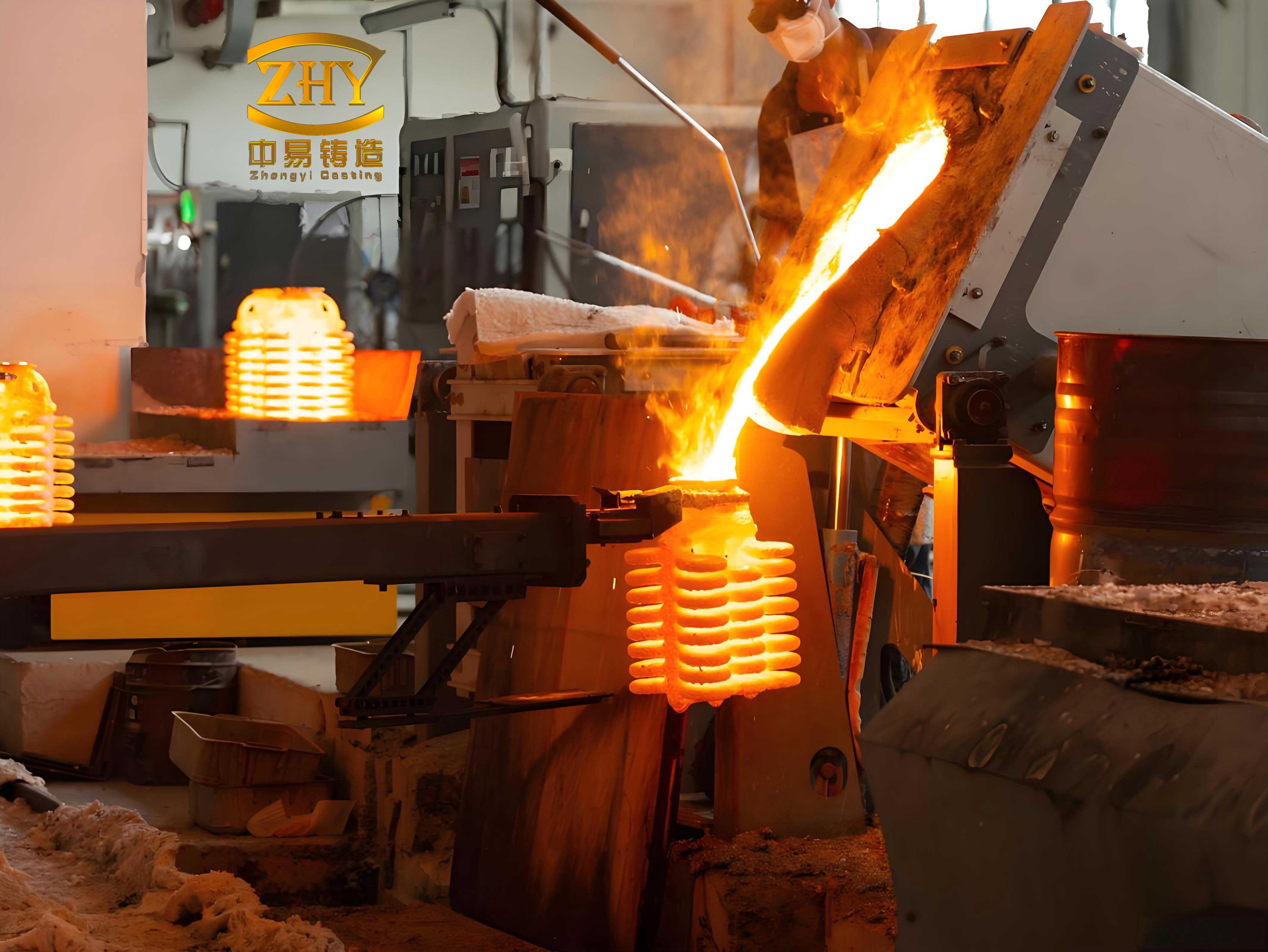
Why investment casting fits a thin-walled micro turbine rotor
Investment casting, also called lost-wax casting, builds a ceramic shell around a wax pattern, removes the wax, fires the shell, and pours liquid metal into the resulting cavity. The process is a near-net-shape route: it can hold CT4–CT6 dimensional grades and Ra 3.2–6.4 µm surface roughness, compared with CT10–CT13 for sand casting and CT5–CT7 for die casting. For the micro turbine rotor, the CT3/Ra 3.2 µm target sits at the high-precision end of the investment-casting range. The twisted blade profile is difficult to machine without leaving stress concentrations, while the 1.3 mm wall and 2 mm root gap make filling, feeding, and distortion control the central process problems.
A workable process therefore has to solve three coupled problems at once: accurate wax-pattern tooling, a strong and permeable ceramic shell, and a thermal history that fills the thin blade sections before they solidify and then feeds the last liquid during solidification. The case study addressed these problems through shrinkage-compensated tooling, a sliding-block wax mold, ProCAST filling-and-solidification simulation, thermal-stress analysis, and a silica-sol shell process.
Tooling and shrinkage compensation
The alloy was a nickel-based superalloy with approximately 50–55 wt% Ni, 17–21 wt% Cr, 2.8–3.3 wt% Mo, and 4.75–5.5 wt% Nb+Ta. Using the difference between the alloy and mold thermal expansion, with an alloy expansion of about 19.8 × 10⁻⁶ mm/mm·°C and a mold expansion of about 11 × 10−6 mm/mm·°C, the linear shrinkage was set at about 2.2%. The mold was made from LD8 forged aluminum, which machines more easily than steel and reduces tooling time.
Because the blades are twisted and the root gap is only 2 mm, a conventional upper/lower split would not release the wax pattern. The mold was split left-to-right with 23 sliding blocks forming the upper halves of the blades. The lower halves were formed by the lower disk, and the upper hub by an aluminum core. The blocks were located by a positioning block and pulled out one by one during opening. Blade-forming surfaces were finished to Ra 0.8 µm, block-to-block mating surfaces to Ra 1.6 µm, and the fit tolerance was ±0.01 mm. Root fillets were R0.3 mm and block dead-corner fillets were R1 mm. A ring runner fed wax from the periphery, and a machined wax ring was later assembled around the blade tips to restrain distortion during casting.
Gating design and initial process window
The initial casting was top-poured, with two parts per mold and a sprue–ingate system. The sprue measured 30 mm × 30 mm × 160 mm. The conical pouring cup had a 130 mm top diameter, a 62 mm bottom diameter, a 61 mm height, and a −45° draft. The ingate at the thick bore section had a 15 mm inner diameter, a 19.4 mm outer diameter, a 17.4 mm height, and a −10° draft. The ingate was placed at the last-to-solidify bore region so that the sprue could feed the casting through the ingate.
The initial process window was a 1480 °C pouring temperature, an 850 °C shell preheat, and a 40 mm/s pouring speed. The speed was calculated from a standard pouring-speed correlation as 39.6 mm/s and rounded to 40 mm/s for simulation. The pouring temperature was about 150 °C above the alloy liquidus of 1332 °C, a superheat intended to improve fluidity in the thin blade sections.
Coupled filling and solidification model
The simulation treated the melt as an incompressible Newtonian fluid with constant density, no inclusions or gas bubbles, and conduction-dominated heat transfer. Radiation and convection were neglected, and the shell was assumed to have uniform permeability. The flow field was solved with the continuity equation, the Navier–Stokes equations, and a volume-of-fluid free-surface equation:
$$\frac{\partial u}{\partial x}+\frac{\partial v}{\partial y}+\frac{\partial w}{\partial z}=0$$
$$\rho\left(\frac{\partial \mathbf{u}}{\partial t}+\mathbf{u}\cdot\nabla\mathbf{u}\right)=-\nabla p+\mu\nabla^{2}\mathbf{u}+\rho\mathbf{g}$$
$$\frac{\partial F}{\partial t}+u\frac{\partial F}{\partial x}+v\frac{\partial F}{\partial y}+w\frac{\partial F}{\partial z}=0$$
Here \(u\), \(v\), and \(w\) are velocity components, \(\rho\) is density, \(p\) is pressure, \(\mu\) is viscosity, \(\mathbf{g}\) is gravity, and \(F\) is the volume fraction of liquid. The thermal field used the energy equation and three-dimensional transient heat conduction:
$$\rho c_p\left(\frac{\partial T}{\partial t}+u\frac{\partial T}{\partial x}+v\frac{\partial T}{\partial y}+w\frac{\partial T}{\partial z}\right)=\nabla\cdot(k\nabla T)+S$$
$$\rho c_p\frac{\partial T}{\partial t}=\nabla\cdot(\lambda\nabla T)+Q$$
where \(T\) is temperature, \(c_p\) is specific heat, \(k\) and \(\lambda\) are thermal conductivities, and \(S\) and \(Q\) are source terms. Latent heat was handled by an enthalpy method:
$$H=\int \rho c_p(T)\,dT$$
The CAD model was imported into Visual-Environment and meshed for ProCAST 2011. The turbine was meshed at 1 mm, the gating system at 5 mm, and the shell at 8 mm. The initial mesh contained 63,526 surface elements and 362,729 volume elements. The shell–casting interface used a heat-transfer coefficient of 500 W/(m²·°C), and gravity was set to 9.8 m/s². The alloy liquidus was 1332 °C, the solidus 1108 °C, and the latent heat 295 kJ/kg. The shell was a silica-sol/zircon system with 4.5–5 layers and a thickness of about 8 mm. Cooling was by air, and the calculation was run until the casting reached 300 °C.
Initial simulation: premature cooling and an isolated hot spot
Filling was smooth and showed no splashing. The velocity field ranged from 0.22 to 3.31 m/s, and the temperature field ranged from 1430 to 1480 °C. Filling was complete at about 3.4 s. At 2.7 s, however, parts of the blade were cooling faster than the rest of the casting and were at risk of premature solidification, so the last liquid might not reach the blade tips. The predicted defect map showed misrun at the blades.
Solidification began at about 3.6 s. The temperature field was nonuniform, especially in the blades. An isolated high-temperature zone formed near the blade tip at 7.40 s and remained liquid after the mid-blade had cooled. The solid-fraction and shrinkage predictions placed porosity in the same region. The single ingate at the bore fed the thick hub, but it did not provide enough late liquid to the thin, thermally isolated blade tips. The initial process therefore had a narrow window: it could fill the part, but it could not reliably feed the last solidifying sections.
Gating redesign and process-window optimization
The redesign added four symmetric ingates at the ring, each with a −8° draft, to shorten the feeding path and increase liquid supply to the blade ring. The new mesh contained 110,604 surface elements and 611,529 volume elements. Filling was complete at 2.96 s, with velocities of 0.37–5.59 m/s and temperatures of 1440–1480 °C. At 2.14 s, the new ingates showed about 1.0 m/s flow, indicating active feeding. No misrun was predicted.
The isolated hot spot near the tip remained, and some porosity was still predicted at 850 °C shell preheat, although the amount was lower than in the initial design. The remaining defects were attributed to the large temperature difference between the 850 °C shell and the 1480 °C melt. Raising the shell preheat to 950–1050 °C and pouring at 1480–1500 °C with a speed of 40–50 mm/s produced no predicted cold shut or shrinkage in the simulation. At 850 °C shell preheat, shrinkage was predicted at the outer ring; at 950 °C and 1050 °C, no cold shut or shrinkage was predicted.
| Parameter | Initial design | Optimized window |
|---|---|---|
| Pouring temperature | 1480 °C | 1480–1500 °C |
| Shell preheat | 850 °C | 950–1050 °C |
| Pouring speed | 40 mm/s | 40–50 mm/s |
| Gating | Sprue plus one ingate per casting; two castings per mold | Added four symmetric ring ingates at −8° draft |
| Predicted outcome | Misrun at blades; shrinkage near the tip | No cold shut or shrinkage at 950–1050 °C shell preheat; reduced thermal stress and distortion |
Thermal stress, hot tearing, and distortion
The thermal history was then used as input to a thermo-elastoplastic stress model. The total strain increment was expressed as the sum of elastic, plastic, and thermal contributions:
$$d\varepsilon_{ij}=d\varepsilon_{ij}^{e}+d\varepsilon_{ij}^{p}+d\varepsilon_{ij}^{T}$$
and the thermal stress scale was estimated from the temperature difference:
$$\sigma=E\alpha\Delta T$$
where \(E\) is elastic modulus, \(\alpha\) is thermal expansion coefficient, and \(\Delta T\) is the local temperature difference. The shell was displacement-constrained, and symmetry conditions were applied on the symmetry plane.
The blade tip cooled fastest, followed by the root, while the ingate region cooled later. The computed effective stress at the tip reached 920–950 MPa, close to the alloy yield strength of 950 MPa at 20 °C. The hot-tearing indicator was also highest at the tip, consistent with the location of maximum constraint and residual stress. Because the ingate solidified later than the tip, the tip was constrained in compression, and the residual stress remained after cooling.
Displacement analysis showed a maximum of 0.6–0.9 mm at the blade tip in the X and Y directions, with little displacement in Z. The Y direction was the gravity axis, which contributed to a slightly larger displacement in Y than in X. The shell preheat comparison showed steeper node-cooling curves and higher first-principal stress at 850 °C than at 950 °C or 1050 °C. At 850 °C, the stress exceeded the local yield strength, so plastic deformation released part of the stress and increased distortion. Raising the shell preheat reduced both residual stress and distortion. Higher pouring temperature improves fluidity but also raises superheat and thermal stress; in this case, shell preheat was the more effective lever for stress control.
Shell-making and casting process design
Wax patterns were injected from a medium-temperature paraffin–stearic acid wax at about 70 °C. The injection pressure was 0.3–0.5 MPa, the die temperature 25–30 °C, and the dwell time 3–5 s. Patterns were quenched in water immediately after ejection to limit distortion, then inspected, repaired, and assembled with 1–2 cm spacing.
Two shell systems were compared. Water-glass shells are cheaper and faster but coarser; silica-sol shells provide the surface quality and dimensional control needed for thin aerospace parts. The case selected a silica-sol binder, GRJ-30, with 29–31% SiO₂, Na₂O below 0.5%, density 1.20–1.22 g/cm³, pH 9–10, viscosity below 8 mm²/s, colloid particle size of 9–20 nm, and a shelf life of over one year.
| Criterion | Water-glass shell | Silica-sol shell |
|---|---|---|
| Surface roughness, Ra | 12.5 µm | 3.2–6.3 µm |
| Dimensional tolerance grade | CT6–CT8 | CT4–CT6 |
| Shell-making cycle | 14 h | 60 h |
| Relative cost | 1.0 | 6.0 |
| Typical use | Carbon steel valves, low-alloy castings | Aerospace turbine blades, thin-walled complex parts |
The shell had a face coat, a transition coat, backup coats, and a seal coat. The face slurry used zircon powder; the transition and backup used calcined kaolinite. The face coat was dried naturally at 23 ± 1 °C and 60–70% relative humidity for 4–6 h. The transition and backup layers were force-dried at 6–8 m/s air speed. The seal coat was dried for more than 14 h.
| Layer | Slurry composition | Density / viscosity | Stucco | Drying |
|---|---|---|---|---|
| Face | Silica sol + zircon powder (36–40 kg per 10 kg sol) + 16 mL wetting agent + 12 mL defoamer | 2.7–2.8 g/cm³; 32 ± 1 s | 100/120 zircon | 23 ± 1 °C; 60–70% RH; 4–6 h |
| Transition | Silica sol + calcined kaolinite (16–17 kg per 10 kg sol) | 1.82–1.85 g/cm³; 19 ± 1 s | 30/60 kaolinite | 23 ± 1 °C; 60–70% RH; over 8 h; 6–8 m/s |
| Backup | Silica sol + calcined kaolinite (14–15 kg per 10 kg sol) | 1.81–1.83 g/cm³; 13 ± 1 s | 16/30 kaolinite | 23 ± 1 °C; 40–60% RH; over 12 h; 6–8 m/s |
| Seal | Backup slurry | Same as backup | None | 23 ± 1 °C; 40–60% RH; over 14 h; 6–8 m/s |
After drying, the molds were dewaxed in a steam autoclave for 10 min, held for 6 h, and fired at 1050 °C for about 45 min. They were poured immediately after firing to retain heat and reduce thermal shock. Preheating also removes moisture and volatiles, strengthens the shell, and reduces the shell–metal temperature gradient. Excessive preheat, however, slows cooling and can degrade mechanical properties, so the 950–1050 °C window is a compromise between filling, feeding, and microstructure control.
The process plan specified medium-frequency coreless induction melting for the superalloy. After casting, accessible defects were repaired by welding, internal porosity was treated by hot isostatic pressing, and surfaces were polished. X-ray or fluorescent inspection was used to check internal quality before final acceptance.
Engineering implications
The case shows that the investment-casting problem for a thin-walled micro turbine rotor is not only a wax-tooling problem. The interaction among gating, local thermal mass, shell preheat, and residual stress sets the process window. A single ingate at the hub can fill the part but cannot feed the blade tips. Adding symmetric ring ingates improves feeding, and raising shell preheat suppresses the remaining shrinkage by reducing the thermal gradient. The tooling solution—left-right sliding blocks, an aluminum core, and 2.2% shrinkage compensation—addresses the pattern side. The shell recipe—a silica-sol/zircon face coat and a kaolinite backup—addresses surface quality, shell strength, and cost.
The resulting process window was 1480–1500 °C pouring temperature, 40–50 mm/s pouring speed, 950–1050 °C shell preheat, and four −8° ring ingates. Because the evidence is simulation-based, this window should be treated as a starting point for trial casting and nondestructive validation rather than a universal specification. The same approach—coupled filling, solidification, and stress modeling—is transferable to other thin-walled investment castings where feeding and distortion compete.