
Rapid investment casting as an indirect additive route
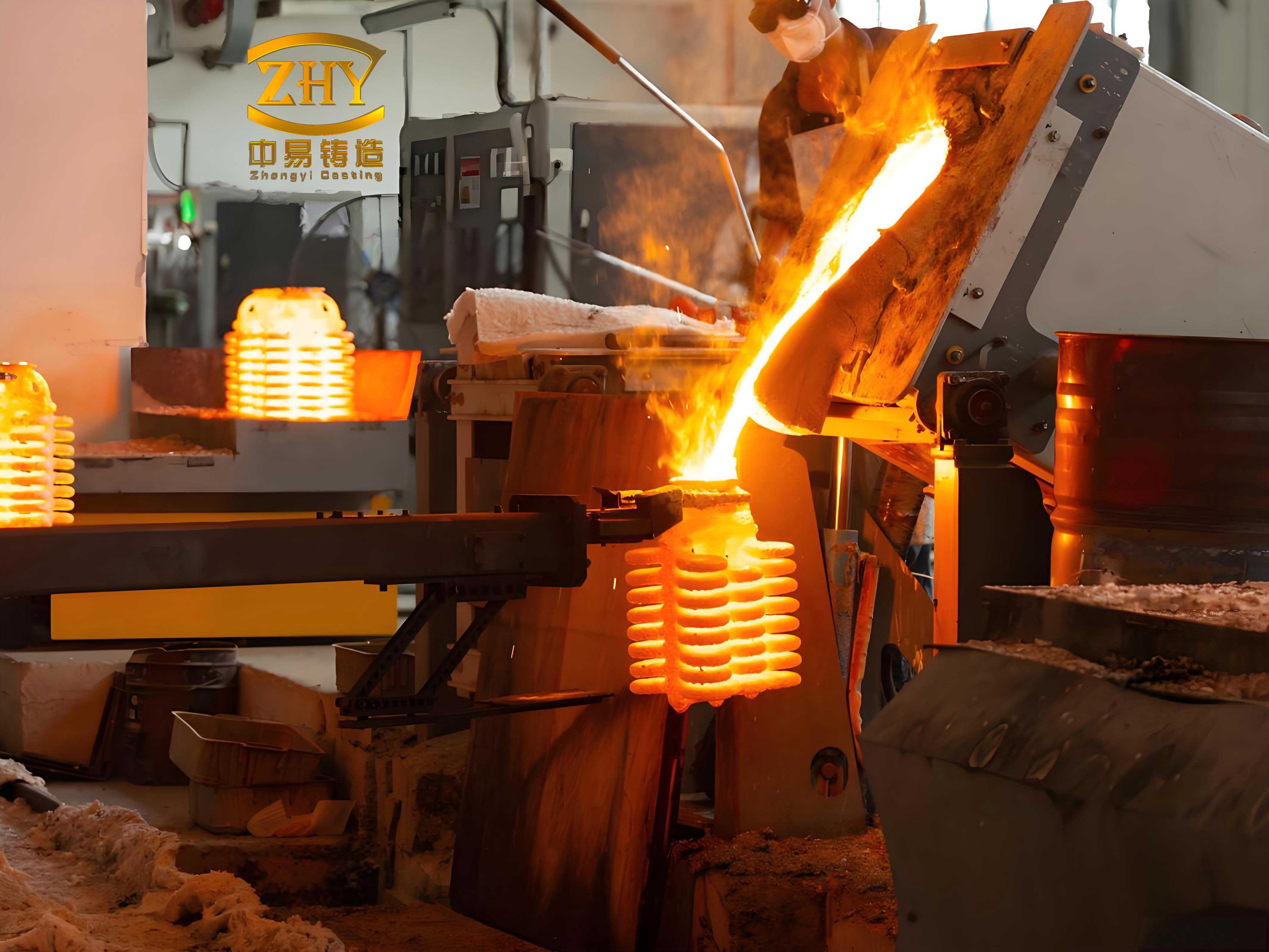
Investment casting is a near-net-shape process in which a sacrificial pattern is coated with refractory slurry, the pattern is removed, the ceramic shell is sintered, and molten metal is poured into the resulting cavity. It is the standard production route for turbine blades and engine casings, components whose wall thickness, internal cooling passages and surface finish cannot be produced by machining alone. Its weakness has always been the pattern: metal dies for wax injection are expensive and slow to make, and they harden every design change into a months-long tooling cycle.
Rapid investment casting (RIC) removes that constraint by printing the pattern directly, typically by stereolithography or filament deposition, and then running the conventional shelling, dewaxing, sintering and pouring sequence. In the taxonomy of metal additive manufacturing, RIC is an indirect process (I-AM): the printed polymer defines the geometry, but the structural material is still cast. Compared with direct additive manufacturing (D-AM) of metal, this split offers several practical advantages — the process chain is already qualified in foundries, feedstock is not restricted to weldable powders, cost per part is lower, part size is limited by the shell and furnace rather than by a build chamber, and there are no metallic supports to cut away.
The economic argument cuts both ways. RIC only pays for itself when the geometry is genuinely complex; for prismatic or simply curved parts, conventional casting or machining remains cheaper and faster. The process is therefore inseparable from a design question: what topology justifies it? That question has two complementary answers — optimization-driven material layout (topology optimization) and experience-driven internal structuring (lattice filling).
From density field to CAD: the interpretation gap
Continuum topology optimization distributes a density field over a design domain and drives it toward an optimal load path. Using the variable-density (SIMP-type) formulation, the problem is stated as
$$\min_{x}\; C=F^{T}D \quad \text{s.t.}\quad \sum_{e} x_e v_e \le f\,V_0,\qquad 0<x_{\min}\le 1,\qquad=""
where $x_e$ is the element density, $C$ the compliance, $K$ the global stiffness matrix, $D$ the displacement vector, $F$ the load vector, $v_e$ the element volume, $V_0$ the design-domain volume and $f$ the permitted volume fraction. Densities near 1 mark material to keep, densities near 0 mark material to remove. The output is a grey-scale field, not a solid model.
The conventional route — look at the iso-surface, then hand-build a CAD model that “follows” it — wastes most of the information the optimization produced. It also depends heavily on the designer’s experience, requires repeated manual re-checking, and typically takes several design-analysis cycles before stress and stiffness targets are met. Because additive manufacturing removes many of the draft, undercut and tool-access constraints that previously forced designers to ignore optimization output, the bottleneck has shifted from fabrication to geometric data handling.
A tighter loop replaces the manual step with a data pipeline: optimize, export the iso-surface as an STL mesh, repair and smooth that mesh, convert it to a solid tetrahedral mesh for verification, extract characteristic curves, and rebuild the CAD model on those curves. Each stage uses a standard tool — the optimizer’s own smoothing module for STL export, reverse-engineering software for mesh doctoring and section-curve extraction, a mesh-to-volume converter for the CAE model, and the CAD system for the final solid.
Mesh quality governs how much work each stage needs. The classification below was used to decide, before any modelling, whether a result could be used directly or needed repair; the four cases examined spanned all four grades, from a plate-like automotive control arm (grade I, clean holes) to a bracket with blurred boundaries and strong internal curvature (grade IV, subdivision required).
| Grade | Mesh condition | Typical geometry | Post-processing |
|---|---|---|---|
| I | Good quality, hole-dominated | Plate-like parts with large flat faces | None; extract features directly |
| II | Fair, clear boundaries, many planar facets | Frame-type brackets | Sand and fit |
| III | Poor, blurred outer boundary, faceted, low internal curvature | Engine brackets | Mesh doctor, sand, smooth, relax, then fit |
| IV | Bad, blurred throughout, high internal curvature | Bionic-type layouts | Mesh doctor plus subdivision |
Three components, three optimization outcomes
The loop was exercised on parts with different material and load characters. The engine bracket is a Ti-6Al-4V casting carrying a concentrated 35,586 N static load from the engine and transmission; its mesh contained 35,290 nodes, 5,728 hexahedral and 131,656 tetrahedral elements. Compliance minimization with a volume constraint, followed by manual stiffening (a base plate to spread bearing area, then one and finally two inclined struts to shorten the load path to the rear arm), gave the comparison below.
| Case | Max deformation (mm) | Max von Mises stress (MPa) | Mass (kg) |
|---|---|---|---|
| Engine bracket, original | 0.14 | 377 | 2.05 |
| Engine bracket, redesigned | 0.30 | 454 | 0.44 |
| Change | +114% | +20% | −78.5% |
| Robot gripper, original | 0.28 | 25.0 | 136.73 |
| Robot gripper, redesigned | 0.29 | 30.5 | 86.40 |
| Change | +3.6% | +22% | −37% |
The gripper, a large welded-steel structure (ASTM A36, 20,000 N normal load at the fingers), was optimized with a demoulding constraint added so the result stayed castable, and its STL was exported at a density threshold of 0.22. Its mesh graded as II, so sanding and fitting sufficed before the volume mesh was generated and passed to the finite-element solver. The preliminary check on the iso-surface itself gave 0.38 mm and 30 MPa, confirming the layout before any CAD work began.
The third case is the more demanding one: an aircraft bearing bracket in 15-5PH stainless steel (AMS 5862), 122.42 × 80.68 × 42.52 mm, minimum wall 3 mm, with four Ø5 mm threaded holes left for later machining. It was optimized under three load cases simultaneously, with a density threshold of 0.20 for STL export.
| Load case | Applied load | Iso-surface: deformation / stress | Final CAD: deformation / stress | Mass |
|---|---|---|---|---|
| 1 | 5,562.5 N, horizontal | 1.05 mm / 898 MPa | 1.10 mm / 821 MPa | 0.859 kg → 0.22 kg (−74.4%) |
| 2 | 8,343.75 N at 45° | 0.99 mm / 1,018 MPa | 0.87 mm / 928 MPa | |
| 3 | 11,125 N, vertical | 0.99 mm / 853 MPa | 0.79 mm / 861 MPa |
The iso-surface exceeded the 1,000 MPa yield strength under case 2, but only in a small, localized region; thickening that region during CAD reconstruction brought the peak down to 928 MPa while the mass stayed at 26% of the original block. This is the practical value of extracting section curves rather than eyeballing the density plot: the reconstruction keeps the load paths the optimizer found while giving the designer explicit control over local thickness, fillets and machining allowances.
Lattice cores: parameter sensitivity in pyramidal panels
Lattice filling addresses the other half of the design space. Instead of removing material, it replaces solid, lightly stressed volume with a periodic truss or shell network, which lowers mass and can improve heat transfer, acoustic damping and energy absorption. Sandwich panels with pyramidal, tetrahedral, Kagome, octet or foam cores are the canonical case, and investment casting is the standard way to make them in superalloys, since the mould is built around the truss rather than machined into it.
For a pyramidal cell with strut length $L$, inclination $\omega$, cell width $B$, height $H$ and strut radius $R$, the geometry is constrained by $H=L\sin\omega$ and $B=2L\cos\omega$, so a parametric model needs only $\omega$, $R$ and $L$. A 6 × 6 array with 3 mm face sheets in IN718 (E = 199.9 GPa, $\nu$ = 0.3, $\rho$ = 8,240 kg/m³) was loaded at 1 MPa in compression with the lower face fixed, varying one parameter at a time.
| Variable | Max deformation (mm) | Max stress (MPa) | Mass (kg) | Deformation/mass (mm/kg) | Stress/mass (MPa/kg) |
|---|---|---|---|---|---|
| L = 24 mm | 0.008 | 80.3 | 1.07 | 0.0075 | 74.7 |
| L = 32 mm | 0.024 | 122.0 | 1.86 | 0.0128 | 65.6 |
| L = 40 mm | 0.056 | 193.1 | 2.70 | 0.0208 | 71.6 |
| L = 48 mm | 0.082 | 293.8 | 3.67 | 0.0224 | 80.0 |
| ω = 30° | 0.070 | 368.0 | 2.89 | 0.024 | 127.3 |
| ω = 45° | 0.024 | 122.0 | 1.86 | 0.013 | 65.6 |
| ω = 60° | 0.010 | 58.8 | 1.12 | 0.009 | 52.5 |
| ω = 70° | 0.003 | 35.2 | 0.65 | 0.004 | 54.2 |
| R = 1.0 mm | 0.041 | 218.6 | 1.63 | 0.025 | 134.1 |
| R = 1.5 mm | 0.024 | 122.0 | 1.86 | 0.013 | 65.6 |
| R = 2.5 mm | 0.011 | 90.8 | 2.08 | 0.005 | 43.7 |
| R = 3.5 mm | 0.006 | 50.9 | 2.47 | 0.002 | 20.6 |
Deformation and stress fall monotonically with increasing strut angle and radius, but mass-normalized metrics do not: stress per unit mass reaches a minimum near $L$ = 32 mm and $\omega$ = 60°, and the radius trades stiffness directly against mass, with 1.5–2.5 mm giving the best balance. The combination $L$ = 32 mm, $\omega$ = 60°, $R$ = 1.5–2.5 mm is therefore the sensible starting point for a cast panel of this density.
Unconventional core topologies
Beyond the classical strut lattices, curved and shell-like core forms can be generated directly in a mesh modelling environment. Two groups of four cores were built to equal mass within each group, with 5 × 5 × 5 mm cells, 3 × 3 cells in plane, two layers through the thickness and 1 mm face sheets, then compared under 1 MPa compression, shear and three-point bending.
| Core (group A) | Compression: def. (mm) / stress (MPa) | Shear: def. (mm) / stress (MPa) | Bending: def. (mm) / stress (MPa) |
|---|---|---|---|
| Sinusboloid | 0.0018 / 37.6 | 0.00088 / 15.2 | 0.00051 / 7.5 |
| Sinuscross | 0.0006 / 20.0 | 0.00038 / 5.3 | 0.00029 / 4.4 |
| Sinusoid3d | 0.0009 / 26.8 | 0.00056 / 12.4 | 0.00040 / 5.3 |
| Sinusphere | 0.0011 / 36.5 | 0.00051 / 14.7 | 0.00041 / 6.8 |
| Core (group B) | Compression: def. (mm) / stress (MPa) | Shear: def. (mm) / stress (MPa) | Bending: def. (mm) / stress (MPa) |
|---|---|---|---|
| Shamrock | 0.00019 / 9.8 | 0.00013 / 3.2 | 0.000065 / 3.5 |
| Star | 0.00018 / 6.7 | 0.00011 / 2.0 | 0.000061 / 3.1 |
| Tetraphylla | 0.00043 / 13.6 | 0.00023 / 3.4 | 0.000100 / 3.8 |
| Torque | 0.00077 / 20.7 | 0.00045 / 6.5 | 0.000240 / 6.1 |
Within group A, Sinuscross was best under all three load cases and Sinusboloid worst — the latter’s single large internal void concentrates strain in a few thin ligaments. Group B ranked Star > Shamrock > Tetraphylla > Torque with consistent ordering across load cases, which suggests that at equal mass the number and distribution of load-bearing ligaments matters more than the nominal wall continuity of the cell.
Lattice-filled turbine blades
High-pressure turbine blades operate under combined centrifugal, aerodynamic and thermal loading, and their cooling architecture is the usual limit on gas entry temperature. Replacing the solid wall-and-rib construction with a lattice-filled airfoil keeps the external shape, wall thickness, height and mass identical while changing the internal load path and the internal surface area available for convective cooling. Three cores — Octahedroid, Hexvase and Octapeak — were inserted into a 15 mm tall section of a conventional blade, retaining only the longitudinal ribs and pin fins of the original internal geometry.
| Blade | Centrifugal: def. (mm) / stress (MPa) | Aerodynamic: def. (mm) / stress (MPa) | Thermal: max / min temperature (°C) |
|---|---|---|---|
| Conventional | 0.00058 / 100 | 0.041 / 470 | 1700 / 1647 |
| Octahedroid core | 0.00041 / 70 | 0.020 / 400 | 1700 / 1520 |
| Hexvase core | 0.00058 / 99 | 0.033 / 410 | 1700 / 1634 |
| Octapeak core | 0.00054 / 88 | 0.025 / 423 | 1700 / 1485 |
The boundary conditions were held identical across the four models: one end fixed with 50 MPa applied for the centrifugal case; 10 MPa on the suction surface and 7 MPa on the pressure surface, taken from the 7–14 MPa range of a rated-condition pressure distribution, for the aerodynamic case; and a transient thermal run from a uniform 1700 °C initial temperature with the same convection coefficient everywhere. Under centrifugal load the Octahedroid core reduced peak stress by 30% and deformation by 29.3%, while Hexvase was essentially equivalent to the conventional blade. Under aerodynamic load all three lattices reduced deformation, by 20–51%, and stress by 10–15%. In the thermal run the conventional blade cooled by 53 °C, Hexvase by 66 °C, Octahedroid by 180 °C and Octapeak by 215 °C, the ranking following the internal surface area each core exposes to the coolant.
These are structural and thermal results from uncoupled analyses, and the ranking must be read with that limitation in mind: in a real blade the metal temperature, the stress field and the coolant flow are mutually dependent, so the natural next step is a conjugate heat transfer treatment rather than separate load cases.
Casting simulation: closing the loop with CACE
A topology that cannot be filled and fed is not a design. The third stage of the chain is therefore casting simulation, using the standard incompressible-flow and heat-transfer formulation. Mass conservation gives
$$\frac{\partial u}{\partial x}+\frac{\partial v}{\partial y}+\frac{\partial w}{\partial z}=0$$
with momentum transport described by the Navier–Stokes equations for a viscous, incompressible melt, and energy transport by the convection–conduction equation with a source term for latent heat release. Shrinkage porosity is predicted with the Niyama criterion, which combines the local temperature gradient with the cooling rate through the solidification interval:
$$\frac{G}{\sqrt{R}},\qquad G=\left|\nabla T\right|=\sqrt{\left(\frac{\partial T}{\partial x}\right)^{2}+\left(\frac{\partial T}{\partial y}\right)^{2}+\left(\frac{\partial T}{\partial z}\right)^{2}},\qquad R=\frac{T_{\text{upper}}-T_{\text{lower}}}{t_{\text{upper}}-t_{\text{lower}}}$$
Low $G/\sqrt{R}$ marks regions that cannot be fed and will therefore contain dispersed porosity; it is normally used together with a critical solid-fraction criterion, since Niyama alone predicts shrinkage cavities better than it predicts microporosity.
For the bearing bracket, a bottom-pour system was selected to keep the metal from impinging on the shell wall, with a riser at the last-solidifying region. Gates were placed at the four threaded bosses, sized at Ø6 × 4 mm from the thermal modulus of the hot spot by the proportional-coefficient method, with a Ø9 × 20 mm sprue, a Ø15 × 140 mm down-sprue and a straight-runner cross-section larger than the gate cross-section so that the vertical temperature gradient favours feeding. The quartz shell was 4 mm thick and preheated to 600 °C, with a pouring temperature of 1,550 °C and a pouring velocity of 30 mm/s estimated from the Kargin relation.
Filling completed in about 13 s: the sprue filled at 2.5 s, the runner and gates at 3.1 s, two streams advanced through the upper arms and the base plate, merged at 6.0 s and 7.1 s, joined into a single front at 8.8 s, and closed at the front end of the bracket. Solidification took 78.82 s and proceeded in the correct order, from the regions far from the riser toward it, giving a predicted porosity volume fraction of 0.7%. Two parameter sweeps followed: pouring temperature from 1,500 to 1,600 °C at 30 mm/s and 600 °C preheat, where defects were minimal at 1,550–1,580 °C (0.45% at 1,580 °C) and worst at 1,600 °C; and shell preheat from 620 to 700 °C, where porosity volume fell monotonically with increasing preheat, since a hotter shell slows the heat extraction that causes premature freezing of thin sections.
A four-level, three-factor array (pouring temperature 1,530–1,600 °C, shell preheat 620–700 °C, pouring velocity 30 or 40 mm/s) over 16 runs identified run 8 — 1,550 °C, 700 °C preheat, 30 mm/s — as the best combination, with the absolute defect fractions in this series being larger than in the single-factor sweeps because the runs were not all evaluated on the same baseline. The ranking, not the absolute percentage, is what the array delivers.
| Factor | Level 1 | Level 2 | Level 3 | Level 4 |
|---|---|---|---|---|
| Pouring temperature (°C) | 1,530 | 1,550 | 1,580 | 1,600 |
| Shell preheat (°C) | 620 | 640 | 680 | 700 |
| Pouring velocity (mm/s) | 40 | 40 | 30 | 30 |
The pyramidal sandwich panel poses a harder filling problem: the truss members are slender, the face sheets are thin, and the melt must rise through a stack of cells without breaking up or freezing early. Its material is IN718 (ρ = 8,220 kg/m³, liquidus 1,310 °C, solidus 1,150 °C, latent heat 293,902 J/kg), cast in a zirconia shell 8 mm thick with a 700 W/(m·K) interface coefficient, preheated to 600 °C, poured at 1,450 °C and 80 mm/s under vacuum. Three slotted gating systems were compared: a double-slot layout with two slots on one side and two reservoir columns opposite; a staggered three-slot layout chosen to avoid melt impingement between the two face sheets; and a four-slot layout with a central gate and opposed columns. Slot thickness was set to 6 mm and column diameter to 24 mm to suit the dense core array.
| Gating system | Fill time (s) | Solidification time (s) | Porosity volume fraction | Observation |
|---|---|---|---|---|
| Double slot | 5.3 | 46.2 | 0.81% | Uniform distribution, stable rise, complete fill |
| Three slot | 4.4 | 36.4 | 3.24% | Stable but incomplete filling of the mould |
| Four slot | 5.5 | — | — | Local freezing after 3 s and impingement; rejected |
In the double-slot system the melt reached the third core layer at 1.7 s, began filling the first cell layer, crossed to the opposite column, and equalized the two free surfaces at 3.3 s before rising steadily to complete filling at 5.3 s — the behaviour expected of slot gating, where the vertical slot feeds the mould layer by layer and the columns act as reservoirs. Solidification again ran from the panel edges and cores toward the slots, though the two face sheets did not freeze symmetrically because the gated side stayed hotter. The three-slot system filled faster but left unfilled regions, and the four-slot version caused premature freezing at the edges plus impingement where the two columns met.
Printability as a design constraint
Before a topology reaches the foundry, its pattern has to be printed, and pattern printability imposes its own geometric rules. Trials on a filament printer in PLA produced the engine bracket (170.69 × 103.57 × 66.36 mm) in 4.3 h, the bearing bracket (122.42 × 80.68 × 42.52 mm) in 2 h 20 min, a 15 × 15 × 10 mm sandwich panel in about 25 min, and a Hexvase-core blade section (38.5 × 31.65 × 15 mm) in 25 min. The lattice samples and the blade section printed without support, which is one of the practical benefits of open-cell topology. The two brackets did not: their overhangs required dense support, and detaching it damaged the finished surfaces.
The remedy is geometric rather than procedural — keep inclined faces below roughly 45° from the build plane, avoid large unsupported spans, and treat the critical angle as a property of the printer and process rather than a universal constant. Slight reorientation of the bearing bracket removed most of the problem. For RIC specifically, this constraint is weaker than in direct metal printing, since the pattern is sacrificial and small surface defects can be polished out before shelling, but the support scars still transfer to the cast surface if they are deep enough.
What the chain still lacks
The three stages — optimization, lattice design, casting simulation — are individually mature, but their integration is not. Feature extraction in the loop described above relied on planar section curves, which works well for the essentially prismatic brackets examined here but degrades on strongly three-dimensional load paths; fitting surfaces directly from the mesh is the obvious extension. The blade results are decoupled structural and thermal analyses, and a coupled thermo-mechanical treatment is needed before the lattice cores can be ranked with confidence. On the casting side, only filling, solidification and shrinkage porosity were evaluated; residual stress and distortion, cold shuts and gas entrapment all affect the same parts and are available in the same simulation environment.
The broader point is that RIC shifts the design constraint rather than removing it. Foundries can now cast what the optimizer produces, but only if the optimizer’s output survives as usable geometry, the lattice is feedable by a real gating system, and the pattern can be printed without support damage. Treating those three conditions as part of one design loop — rather than as sequential hurdles after the concept is frozen — is what makes the process economically defensible.