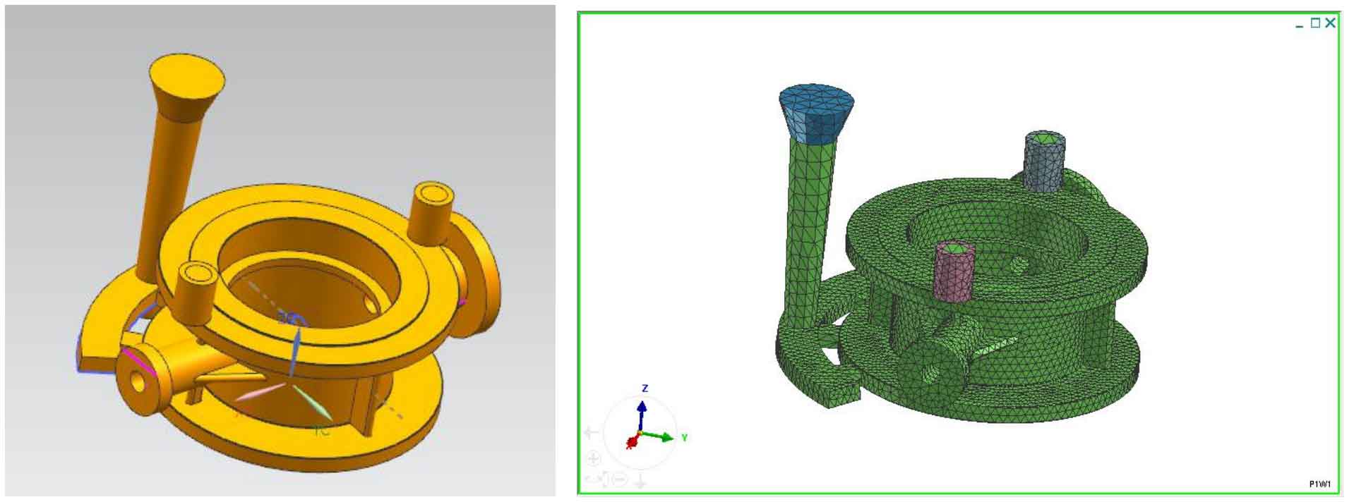
According to the simulation results of lost foam casting defects of cast steel valve body and the comprehensive analysis of the location distribution of shrinkage cavity and porosity defects of lost foam castings of cast steel valve body poured by the first process scheme, the position and size of riser are redesigned. In order to ensure that the liquid metal in the riser can feed enough into the mold cavity without thermal heating at the geometric hot joint, the riser should be placed close to the hot joint and avoid being placed directly above the hot joint. The three-dimensional model of riser design is shown in Figure 1:
Then, the solidification process of molten metal in the lost foam casting of cast steel valve body is simulated and analyzed, and the analysis results are shown in Fig. 2.
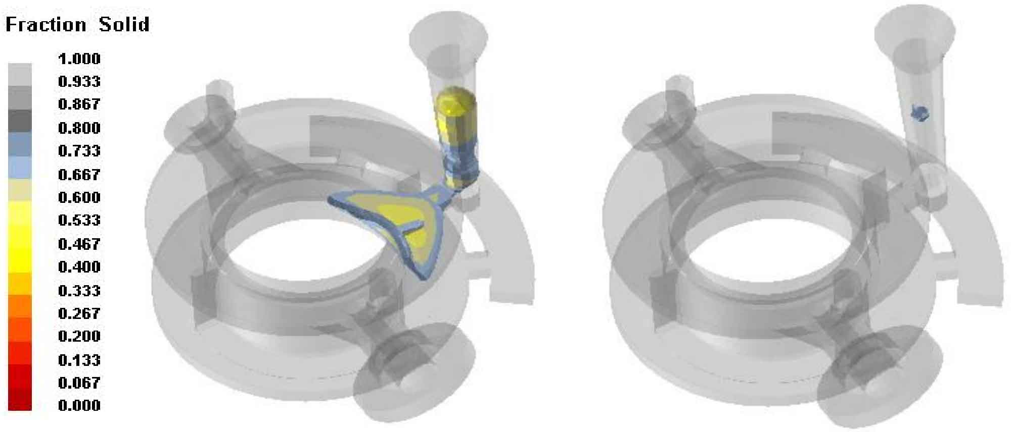
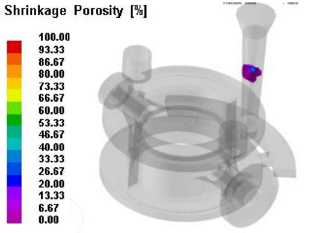
It can be seen from Fig. 2 that there is no isolated liquid phase area after the process is improved. Figure 3 shows the distribution of shrinkage cavity and porosity of cast steel valve body lost foam casting. It can be seen that there are no shrinkage cavity and porosity defects in the cast steel valve body lost foam casting, and the shrinkage cavity and porosity are only distributed at the sprue.